US2835299A - Removable drum type tobacco cutting machine with fixed grinding means - Google Patents
Removable drum type tobacco cutting machine with fixed grinding means Download PDFInfo
- Publication number
- US2835299A US2835299A US408525A US40852554A US2835299A US 2835299 A US2835299 A US 2835299A US 408525 A US408525 A US 408525A US 40852554 A US40852554 A US 40852554A US 2835299 A US2835299 A US 2835299A
- Authority
- US
- United States
- Prior art keywords
- cutter
- frame
- mouthpiece
- drum
- grinding
- Prior art date
- Legal status (The legal status is an assumption and is not a legal conclusion. Google has not performed a legal analysis and makes no representation as to the accuracy of the status listed.)
- Expired - Lifetime
Links
- 241000208125 Nicotiana Species 0.000 title description 23
- 235000002637 Nicotiana tabacum Nutrition 0.000 title description 23
- 238000005520 cutting process Methods 0.000 title description 11
- 238000010276 construction Methods 0.000 description 3
- 239000000654 additive Substances 0.000 description 1
- 230000000996 additive effect Effects 0.000 description 1
- 238000004140 cleaning Methods 0.000 description 1
- 229910003460 diamond Inorganic materials 0.000 description 1
- 239000010432 diamond Substances 0.000 description 1
- 238000007599 discharging Methods 0.000 description 1
- 239000000428 dust Substances 0.000 description 1
- 239000002245 particle Substances 0.000 description 1
- 230000002093 peripheral effect Effects 0.000 description 1
- 230000008439 repair process Effects 0.000 description 1
- 239000011435 rock Substances 0.000 description 1
Images

Classifications
-
- A—HUMAN NECESSITIES
- A24—TOBACCO; CIGARS; CIGARETTES; SIMULATED SMOKING DEVICES; SMOKERS' REQUISITES
- A24B—MANUFACTURE OR PREPARATION OF TOBACCO FOR SMOKING OR CHEWING; TOBACCO; SNUFF
- A24B7/00—Cutting tobacco
- A24B7/04—Cutting tobacco by machines with revolving knives
- A24B7/08—Cutting tobacco by machines with revolving knives with several knives which act one after the other
- A24B7/12—Cutting tobacco by machines with revolving knives with several knives which act one after the other with cutter axes transverse to the feeding direction
-
- Y—GENERAL TAGGING OF NEW TECHNOLOGICAL DEVELOPMENTS; GENERAL TAGGING OF CROSS-SECTIONAL TECHNOLOGIES SPANNING OVER SEVERAL SECTIONS OF THE IPC; TECHNICAL SUBJECTS COVERED BY FORMER USPC CROSS-REFERENCE ART COLLECTIONS [XRACs] AND DIGESTS
- Y10—TECHNICAL SUBJECTS COVERED BY FORMER USPC
- Y10T—TECHNICAL SUBJECTS COVERED BY FORMER US CLASSIFICATION
- Y10T83/00—Cutting
- Y10T83/303—With tool sharpener or smoother
-
- Y—GENERAL TAGGING OF NEW TECHNOLOGICAL DEVELOPMENTS; GENERAL TAGGING OF CROSS-SECTIONAL TECHNOLOGIES SPANNING OVER SEVERAL SECTIONS OF THE IPC; TECHNICAL SUBJECTS COVERED BY FORMER USPC CROSS-REFERENCE ART COLLECTIONS [XRACs] AND DIGESTS
- Y10—TECHNICAL SUBJECTS COVERED BY FORMER USPC
- Y10T—TECHNICAL SUBJECTS COVERED BY FORMER US CLASSIFICATION
- Y10T83/00—Cutting
- Y10T83/485—Cutter with timed stroke relative to moving work
Definitions
- the present invention relates ⁇ to a tobacco cutting machine and is particularly concerned with a drum cutter inv which the tobacco leaves are fed to a mouthpiece by conveyor means and having a cutter drum rotatable transversely in front of the mouthpiece and removable therefrom and a grinding device for grinding the cutters fitted to the periphery of the cutter ⁇ drum.
- Drum tobacco cutters are known in which the cutter drum andthe grinding device are supported on a common mounting. ln order to begin the cutting operation or be able to inspect the mouthpiece the mounting with the cutter drum supported thereon is removed from the mouthpiece either about an axis which is located vertically at one side of the machine frame or about an axis which lies horizontally below the mouthpiece. On turning away or removing themonnting with the cutter drum and the grinding device comparatively large masses consequently must be moved by the attendant.
- the grinding device is associated with the machine frame while the cutter, drum is supported in a frame separate therefrom and can be rocked away from the mouthpiece or otherwise removed and can be brought out of engagement with the grinding device.
- the result is obtained that the movable assembly can be made lighter since it only has to carry the cutter drum.
- the overall length of the machine is considerably shortened if the grinding device is, as is preferred, arranged above the cutter drum.
- a better grinding action is obtained since the grinding device remains associated with the major mass of the machine frame.
- Tobacco drum cutters are, of course, known in which only the cutter drum is moved away from the mouthpiece toward the grinding device. These constructions have, however, the disadvantage that they can either only be operated for cutting or for grinding while according to the invention grinding and cutting can be simultaneously performed.
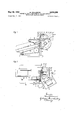
- Fig. 1 is a side view of a tobacco drum cutter with the cutter drum mounting in theworking position.
- Fig. 2 is a View from above of the tobacco cutter but with the cutter drum mounting turned out of the operative position.
- FIG. 3 is an enlarged partial section through the to bacco cutter according to Fig. l, and
- Fig. 4 is a view from above of the grinding device on a larger scale.
- the tobacco 1 is pressed in known manner, for example continuously, through a mouthpiece 2, by ⁇ means of conveyor belts 3 and 4 converging tof wards the mouthpiece and travelling in the direction of the arrowsY (see also Fig. 1) and which are driven by a suitable driving device for example electric motor 5 through a ⁇ belt ⁇ 5a and a reduction gear trainSb likewise in known manner.
- a cutter drum 7 rotates in front of the mouthpiece 2 ⁇ in the directionv of the arrow 7. having for example ve cutters 6 ⁇ on its periphery and by which the tobacco leaving the mouthpiece is cut. The cutters 6 are adjusted during rotation of ⁇ the.
- the cutter drum 7 by means of the known devices ⁇ 6a and are sharpened by the grinding wheels ⁇ 29 and ⁇ 30, in similar manner as disclosed in Arthur Ritschers United States patent specification 2,751,949, issued lune 26, 1956.
- the cutter drum 7 is driven for example by a driving motor 9 connected by its iiange 9a to a frame 8 (see, also Fig. 2).
- the frame 8 ⁇ with the cutter drum ⁇ 7, driving motor 9 and the tobacco delivery funnel 1,0 (see Fig. 23) is pivotally mounted Von the stationary machine frame 15 (see Figures 1 and 2) by means of hinges 12, 12".
- the frame 8 is ⁇ locked by a device 13, to the stationary ⁇ machine frame 15,.
- the grinding device described in further detail below is arranged above the cutter drum 7 (see Fig, 3) which device is mounted to ⁇ the top of the machine frame 1,5 of the tobacco cutter.
- Two bearing brackets 16 and 17 secured in suitable manner to the top portion of the machine frame 15' carry two guide bars 18, 18 arranged one over the other ⁇ and preferably parallel to the cutter drum axis.
- a longitudinally reciprocable slider body 2,1 is supported on the guide bars 18, 18 (see Figs. 3 ⁇ and4), the ⁇ rear side of which carries a pin 31 on which a connecting rod 32 is attached which is driven by a crank 33 for example from a driving motor 34 supported on the machine frame 15.
- a plate 22 of dovetail form which can slide up and down on the hori zontally movable slider member 21 by means of a ratchet wheel 23 fixed to a vertical screw spindle 24.
- the ratchet wheel 23 is operated by a pawl 25 which receives its movement from a lever 26 which travels by its other end during the reciprocation of the slider body 21 on the stationary cam tracks 27 and 27'.
- An electric motor 28, with for example a grinding wheel 29, 30 on each end of the shaft, is mounted on the plate 22. This movement at right angles to the reciprocatory movement and coupled thereto in the same manner as in machine tools has the elect that as the grinding wheels become smaller the motor with the two wheels can be fed automatically to the cutters.
- the grinding is here elected in such a way that each grinding Wheel overlaps in its movement the centre of the cutter length by about 5 mm.
- The'trueing of the grinding wheels is effected in known manner by two adjustable diamond trueing devices 35, 35 which are arranged below the grinding wheels but outside the path of the cutters and preferably at a suitable point of the frame 3 in a suitable support device.
- the grinding dust, produced by grinding the cutters is collected in a container 36 from which it can be drawn off vin some cases by means of lateral apertures 37, 37' connected to a suction device of known kind.
- the cutter drum is arranged squarely or inclined to the mouthpiece since the inclination of the guide bars 18, 18' can be arranged to correspond to that ofthe cutter drum.
- a rotary tobacco cutter comprising a machine frame having an enlarged elongated discharge passage forming a mouthpiece for discharging tobacco, means mounted in said machine frame for feeding tobacco to said mouthpiece, a cutter frame hingedly connected to said machine frame on one side of said mouthpiece to swing horizontally to and from said mouthpiece, a grinding wheel mounted on said machine frame to move horizontally above said cutter frame parallel to said mouthpiece, a rotary cutter supported by said cutter frame having a plurality of circumferentially spaced knives to co-act with said mouthpiece and cut the tobacco into comminuted particles, means on said cutter frame for latching the swinging end of said cutter frame in position to hold the same to the machine frame in position below said grinding wheel and means supported on the rotary cutter frame for dressing the grinding wheel as the same is moved horizontally to traverse the cutting blades.
- a rotary tobacco cutter comprising a machine frame having an elongated discharge opening forming a mouthpiece, endless conveyor means mounted in said machine frame for feeding tobacco to said mouthpiece, a cutter frame hingedly connected to said machine frame on one side of said mouthpiece to swing horizontally toward and away from said mouthpiece, cutter blades carried by said cutter frame and arranged to rotate in spaced relation from said mouthpiece, a grinding wheel mounted on said machine frame to move horizontally above said cutter frame parallel with said mouthpiece, means on said cutter frame for latching the swinging end of said cutter frame in a locked position on the machine frame to position said cutter blades beneath said grinding wheel, and grinding wheel dressing tools mounted on the rotary cutter frame adapted to dress the grinding wheel peripheral surfaces when the grinding Wheel is' moved horizontally to traverse said cutter blades and an electric motor mounted on said rotary cutter frame having a power shaft drivingly connected to said cutter blades to rotate the same in slightly spaced relation from the edge of said mouthpiece, said cutter framek being normally positioned beneath said grinding wheel and being adapted to be moved away from
Landscapes
- Manufacture Of Tobacco Products (AREA)
Description
May 20, 1958 M. POLLMANN 2,835Q299 REMovABLE DRUM TYPE TOBACCO CUTTING MACHINE WITH FIXED .CRINDINC MEANS Filed Feb. 5. 1954 2 SheebSSheeb l May 20, 1958 M POLLMANN 2,835,299
'REMOVABLE DRUM TYPE TOBACCO CUTTING MACHINE WITH FIXED GRINDING MEANS Filed Feb. 5. 1354 2 SheG'bS-Shee'b 2 United States Patent O REMOVABLE DRUM TYPE TOBACCO CUTTING MACHINE WITH FllXED GRINDING MEANS Max Pollmann, Hamburg-Bergedorf, Germany, assignor to KurtKorber & Co. K. G., Hamburg-Bergedorf, Germany Application February 5, 1954, Serial'No'. 408,525 Claims priority, application Germany February 16, 1953 3` Claims. (Cl. 14E-119) The present invention relates` to a tobacco cutting machine and is particularly concerned with a drum cutter inv which the tobacco leaves are fed to a mouthpiece by conveyor means and having a cutter drum rotatable transversely in front of the mouthpiece and removable therefrom and a grinding device for grinding the cutters fitted to the periphery of the cutter` drum.
Drum tobacco cutters are known in which the cutter drum andthe grinding device are supported on a common mounting. ln order to begin the cutting operation or be able to inspect the mouthpiece the mounting with the cutter drum supported thereon is removed from the mouthpiece either about an axis which is located vertically at one side of the machine frame or about an axis which lies horizontally below the mouthpiece. On turning away or removing themonnting with the cutter drum and the grinding device comparatively large masses consequently must be moved by the attendant. To this disadvantage there is also added a further disadvantage that the vibration occurring during rotation of the` cutter drum and of the grinding wheels and during the reciprocatory movement thereof along the cutter edges aiect one another mutually and in some cases are additive whereby thc cutting operation and the grinding of the cutters become inexact.
These disadvantages are eliminated according to the invention by the fact that the grinding device is associated with the machine frame while the cutter, drum is supported in a frame separate therefrom and can be rocked away from the mouthpiece or otherwise removed and can be brought out of engagement with the grinding device. Ey this construction the result is obtained that the movable assembly can be made lighter since it only has to carry the cutter drum. Moreover the overall length of the machine is considerably shortened if the grinding device is, as is preferred, arranged above the cutter drum. Finally a better grinding action is obtained since the grinding device remains associated with the major mass of the machine frame.
Tobacco drum cutters are, of course, known in which only the cutter drum is moved away from the mouthpiece toward the grinding device. These constructions have, however, the disadvantage that they can either only be operated for cutting or for grinding while according to the invention grinding and cutting can be simultaneously performed.
One constructional form of the invention is shown by way of example on the accompanying drawings wherein:
Fig. 1 is a side view of a tobacco drum cutter with the cutter drum mounting in theworking position.
Fig. 2 is a View from above of the tobacco cutter but with the cutter drum mounting turned out of the operative position.
l Fig. 3 is an enlarged partial section through the to bacco cutter according to Fig. l, and
Fig. 4 is a view from above of the grinding device on a larger scale.
As shown in Fig. 3 the tobacco 1 is pressed in known manner, for example continuously, through a mouthpiece 2, by`means of conveyor belts 3 and 4 converging tof wards the mouthpiece and travelling in the direction of the arrowsY (see also Fig. 1) and which are driven by a suitable driving device for example electric motor 5 through a` belt` 5a and a reduction gear trainSb likewise in known manner. A cutter drum 7 rotates in front of the mouthpiece 2` in the directionv of the arrow 7. having for example ve cutters 6` on its periphery and by which the tobacco leaving the mouthpiece is cut. The cutters 6 are adjusted during rotation of` the. drum 7 by means of the known devices` 6a and are sharpened by the grinding wheels` 29 and` 30, in similar manner as disclosed in Arthur Ritschers United States patent specification 2,751,949, issued lune 26, 1956. The cutter drum 7 is driven for example by a driving motor 9 connected by its iiange 9a to a frame 8 (see, also Fig. 2).
In order to` provide ready access to the mouthpiece 2 the frame 8` with the cutter drum` 7, driving motor 9 and the tobacco delivery funnel 1,0 (see Fig. 23) is pivotally mounted Von the stationary machine frame 15 (see Figures 1 and 2) by means of hinges 12, 12". During cutting` the frame 8 is` locked by a device 13, to the stationary` machine frame 15,.
The grinding device described in further detail below is arranged above the cutter drum 7 (see Fig, 3) which device is mounted to` the top of the machine frame 1,5 of the tobacco cutter.
Two bearing brackets 16 and 17 secured in suitable manner to the top portion of the machine frame 15' carry two guide bars 18, 18 arranged one over the other` and preferably parallel to the cutter drum axis. A longitudinally reciprocable slider body 2,1 is supported on the guide bars 18, 18 (see Figs. 3` and4), the` rear side of which carries a pin 31 on which a connecting rod 32 is attached which is driven by a crank 33 for example from a driving motor 34 supported on the machine frame 15.
On the other side of the slider body 21 is a plate 22 of dovetail form which can slide up and down on the hori zontally movable slider member 21 by means of a ratchet wheel 23 fixed to a vertical screw spindle 24. The ratchet wheel 23 is operated by a pawl 25 which receives its movement from a lever 26 which travels by its other end during the reciprocation of the slider body 21 on the stationary cam tracks 27 and 27'. An electric motor 28, with for example a grinding wheel 29, 30 on each end of the shaft, is mounted on the plate 22. This movement at right angles to the reciprocatory movement and coupled thereto in the same manner as in machine tools has the elect that as the grinding wheels become smaller the motor with the two wheels can be fed automatically to the cutters. The grinding is here elected in such a way that each grinding Wheel overlaps in its movement the centre of the cutter length by about 5 mm.
The'trueing of the grinding wheels is effected in known manner by two adjustable diamond trueing devices 35, 35 which are arranged below the grinding wheels but outside the path of the cutters and preferably at a suitable point of the frame 3 in a suitable support device. The grinding dust, produced by grinding the cutters is collected in a container 36 from which it can be drawn off vin some cases by means of lateral apertures 37, 37' connected to a suction device of known kind.
It is of no importance for the basic construction of the invention whether the cutter drum is arranged squarely or inclined to the mouthpiece since the inclination of the guide bars 18, 18' can be arranged to correspond to that ofthe cutter drum.
What I claim is:
1. A rotary tobacco cutter, comprising a machine frame having an enlarged elongated discharge passage forming a mouthpiece for discharging tobacco, means mounted in said machine frame for feeding tobacco to said mouthpiece, a cutter frame hingedly connected to said machine frame on one side of said mouthpiece to swing horizontally to and from said mouthpiece, a grinding wheel mounted on said machine frame to move horizontally above said cutter frame parallel to said mouthpiece, a rotary cutter supported by said cutter frame having a plurality of circumferentially spaced knives to co-act with said mouthpiece and cut the tobacco into comminuted particles, means on said cutter frame for latching the swinging end of said cutter frame in position to hold the same to the machine frame in position below said grinding wheel and means supported on the rotary cutter frame for dressing the grinding wheel as the same is moved horizontally to traverse the cutting blades.
2. A rotary tobacco cutter, comprising a machine frame having an elongated discharge opening forming a mouthpiece, endless conveyor means mounted in said machine frame for feeding tobacco to said mouthpiece, a cutter frame hingedly connected to said machine frame on one side of said mouthpiece to swing horizontally toward and away from said mouthpiece, cutter blades carried by said cutter frame and arranged to rotate in spaced relation from said mouthpiece, a grinding wheel mounted on said machine frame to move horizontally above said cutter frame parallel with said mouthpiece, means on said cutter frame for latching the swinging end of said cutter frame in a locked position on the machine frame to position said cutter blades beneath said grinding wheel, and grinding wheel dressing tools mounted on the rotary cutter frame adapted to dress the grinding wheel peripheral surfaces when the grinding Wheel is' moved horizontally to traverse said cutter blades and an electric motor mounted on said rotary cutter frame having a power shaft drivingly connected to said cutter blades to rotate the same in slightly spaced relation from the edge of said mouthpiece, said cutter framek being normally positioned beneath said grinding wheel and being adapted to be moved away from said mouthpiece and machine frame for repairs and cleaning purposes.
3. in a tobacco cutting machine, a frame having an elongated horizontal discharge opening forming a mouthpiece7 means mounted in said frame for feeding tobacco to said mouthpiece, a rotary cutter drum frame hinged to said first named frame on one side of said mouthpiece to swing toward and away from said mouthpiece, a rotary cutter drum mounted in said cutter drum frame, motor means carried by said cutter drum frame drivingly connected to said cutter drum, latching means on the free swinging end of said rotary cutter drum frame for locking said frame to said first named frame so that the knives of the cutter drum will cooperate with said mouthpiece to cut tobacco fed therethrough, horizontal guide-- ways on said first named frame arranged parallel to said mouthpiece, a horizontally movable carriage movable along said guideways a grinder having a rotary grinding wheel on said carriage whereby upon movement of said carriage the grinding wheel of said grinder will sharpen the knives of said rotary cutter when the rotary cutter frame is in its locked position, means supported by said first mentioned frame for reciprocating said carriage to cause the grinder to traverse the knives of said rotary cutter, and means attached to said carriage for feeding said grinder downward toward the rotary cutter drum, said motor for driving the rotary cutter drum being mounted on the cutter drum frame and adapted to rock therewith when said cutter drum frame is moved toward and away from said mouthpiece,
References Cited in the le of this patent `UNITED STATES PATENTS Re. 12,534 Stewart et al Sept. 25, 1906 2,464,896 Schreiber Mar. 22, 1949 2,476,177 Bloom et al. July 12, 1949 2,690,777 Korber et a1 Oct. 5, 1954
Applications Claiming Priority (1)
| Application Number | Priority Date | Filing Date | Title |
|---|---|---|---|
| DE2835299X | 1953-02-16 |
Publications (1)
| Publication Number | Publication Date |
|---|---|
| US2835299A true US2835299A (en) | 1958-05-20 |
Family
ID=7999350
Family Applications (1)
| Application Number | Title | Priority Date | Filing Date |
|---|---|---|---|
| US408525A Expired - Lifetime US2835299A (en) | 1953-02-16 | 1954-02-05 | Removable drum type tobacco cutting machine with fixed grinding means |
Country Status (1)
| Country | Link |
|---|---|
| US (1) | US2835299A (en) |
Cited By (9)
| Publication number | Priority date | Publication date | Assignee | Title |
|---|---|---|---|---|
| US3044225A (en) * | 1958-02-27 | 1962-07-17 | Hauni Werke Koerber & Co Kg | Cutting machines for fibrous materials |
| US3170498A (en) * | 1959-12-07 | 1965-02-23 | Schmermund Maschf Alfred | Tobacco cutting machine with rotating knife top |
| US3297068A (en) * | 1964-03-04 | 1967-01-10 | Evert V Bloomquist | Machine for cutting material into strips |
| US3584668A (en) * | 1969-02-27 | 1971-06-15 | Amf Inc | Knives in cutting machines |
| US3633833A (en) * | 1969-12-04 | 1972-01-11 | Stanley V Ehrlich | Machine with self-sharpening means for cutting scrap materials into chips |
| DE3332559A1 (en) * | 1982-11-15 | 1984-05-17 | Hesston Corp., Hesston, Kan. | ARMING DEVICE FOR THE CUTTER CYLINDER OF A HARVESTING MACHINE |
| US4984491A (en) * | 1986-02-13 | 1991-01-15 | Comas S.P.A. | Rotary cutting head, particularly for tobacco cutting machines |
| EP1535523A3 (en) * | 2003-11-25 | 2005-06-08 | Hauni Primary GmbH | Devices and method to separate tobacco from a tobacco block |
| US20120267458A1 (en) * | 2009-09-29 | 2012-10-25 | Dickinson Legg Limited | Cutting and grinding apparatus |
Citations (3)
| Publication number | Priority date | Publication date | Assignee | Title |
|---|---|---|---|---|
| US2464896A (en) * | 1943-09-18 | 1949-03-22 | Schreiber Patrick Quint Robert | Machine for cutting leaf tobacco and the like |
| US2476177A (en) * | 1945-10-18 | 1949-07-12 | Allis Chalmers Mfg Co | Forage harvester knife sharpener |
| US2690777A (en) * | 1950-10-28 | 1954-10-05 | Koerber & Co Kg | Rotary tobacco cutter having a vertical reciprocating trimming knife |
-
1954
- 1954-02-05 US US408525A patent/US2835299A/en not_active Expired - Lifetime
Patent Citations (3)
| Publication number | Priority date | Publication date | Assignee | Title |
|---|---|---|---|---|
| US2464896A (en) * | 1943-09-18 | 1949-03-22 | Schreiber Patrick Quint Robert | Machine for cutting leaf tobacco and the like |
| US2476177A (en) * | 1945-10-18 | 1949-07-12 | Allis Chalmers Mfg Co | Forage harvester knife sharpener |
| US2690777A (en) * | 1950-10-28 | 1954-10-05 | Koerber & Co Kg | Rotary tobacco cutter having a vertical reciprocating trimming knife |
Cited By (12)
| Publication number | Priority date | Publication date | Assignee | Title |
|---|---|---|---|---|
| US3044225A (en) * | 1958-02-27 | 1962-07-17 | Hauni Werke Koerber & Co Kg | Cutting machines for fibrous materials |
| US3170498A (en) * | 1959-12-07 | 1965-02-23 | Schmermund Maschf Alfred | Tobacco cutting machine with rotating knife top |
| US3297068A (en) * | 1964-03-04 | 1967-01-10 | Evert V Bloomquist | Machine for cutting material into strips |
| US3584668A (en) * | 1969-02-27 | 1971-06-15 | Amf Inc | Knives in cutting machines |
| US3633833A (en) * | 1969-12-04 | 1972-01-11 | Stanley V Ehrlich | Machine with self-sharpening means for cutting scrap materials into chips |
| DE3332559A1 (en) * | 1982-11-15 | 1984-05-17 | Hesston Corp., Hesston, Kan. | ARMING DEVICE FOR THE CUTTER CYLINDER OF A HARVESTING MACHINE |
| US4503643A (en) * | 1982-11-15 | 1985-03-12 | Hesston Corporation | Sharpener assembly for the cutting cylinder of a crop harvester |
| US4984491A (en) * | 1986-02-13 | 1991-01-15 | Comas S.P.A. | Rotary cutting head, particularly for tobacco cutting machines |
| EP1535523A3 (en) * | 2003-11-25 | 2005-06-08 | Hauni Primary GmbH | Devices and method to separate tobacco from a tobacco block |
| CN100584226C (en) * | 2003-11-25 | 2010-01-27 | 豪尼制丝设备责任有限公司 | Devices and method to separate tobacco from a tobacco block |
| US20120267458A1 (en) * | 2009-09-29 | 2012-10-25 | Dickinson Legg Limited | Cutting and grinding apparatus |
| US9474302B2 (en) * | 2009-09-29 | 2016-10-25 | Dickinson Legg Limited | Cutting and grinding apparatus, method of manufacture of cut lengths of tobacco, and method for controlling the operation of a cutting apparatus |
Similar Documents
| Publication | Publication Date | Title |
|---|---|---|
| US2835299A (en) | Removable drum type tobacco cutting machine with fixed grinding means | |
| US3748786A (en) | Apparatus for sharpening rotary cutters for tobacco or the like | |
| US3857520A (en) | Oscillating anvil disintegrator | |
| RU2263453C2 (en) | Cutting machine for organic materials of plant origin, in particular, for tobacco | |
| US2690777A (en) | Rotary tobacco cutter having a vertical reciprocating trimming knife | |
| US2830634A (en) | Adjusting device for sharpener for tobacco cutter | |
| US2795229A (en) | Cigarette machine feed | |
| US2738629A (en) | Tobacco cutter grinding means | |
| US2763307A (en) | Machine for cutting tobacco and the like | |
| US2048473A (en) | Tobacco cutting machine | |
| BE1001510A6 (en) | Device for cutting of damaged cigarettes and tobacco recover it. | |
| US2848030A (en) | Tobacco cutting machine | |
| US1956925A (en) | Machine for taking tobacco out of cigarettes | |
| US1801929A (en) | Combination feed grinder | |
| US4306574A (en) | Machine for shredding tobacco or the like | |
| US2546727A (en) | Tobacco cutting machine | |
| GB750639A (en) | Improvements in tobacco cutting machines | |
| GB437272A (en) | Improvements in tobacco cutting machines | |
| US2338995A (en) | Sharpener for meat-chopping machines | |
| GB658892A (en) | Improvements in or relating to machines for cutting leaf tobacco and similar materials | |
| SU1782748A1 (en) | Shaving manufacturing device | |
| CN209537518U (en) | Staking machine | |
| CN113102025B (en) | Electric branch crusher for superfine grinding | |
| US327885A (en) | New yoek | |
| US1417741A (en) | Automatic feeder |