US2829574A - Photographic shutter - Google Patents
Photographic shutter Download PDFInfo
- Publication number
- US2829574A US2829574A US389775A US38977553A US2829574A US 2829574 A US2829574 A US 2829574A US 389775 A US389775 A US 389775A US 38977553 A US38977553 A US 38977553A US 2829574 A US2829574 A US 2829574A
- Authority
- US
- United States
- Prior art keywords
- scale
- shutter
- aperture
- speed
- diaphragm
- Prior art date
- Legal status (The legal status is an assumption and is not a legal conclusion. Google has not performed a legal analysis and makes no representation as to the accuracy of the status listed.)
- Expired - Lifetime
Links
- 230000008878 coupling Effects 0.000 description 29
- 238000010168 coupling process Methods 0.000 description 29
- 238000005859 coupling reaction Methods 0.000 description 29
- 238000010276 construction Methods 0.000 description 21
- 230000008859 change Effects 0.000 description 12
- 230000007246 mechanism Effects 0.000 description 9
- 230000008901 benefit Effects 0.000 description 7
- 230000003340 mental effect Effects 0.000 description 7
- 230000000295 complement effect Effects 0.000 description 6
- 230000002596 correlated effect Effects 0.000 description 5
- 230000000875 corresponding effect Effects 0.000 description 5
- 239000012925 reference material Substances 0.000 description 3
- 238000013459 approach Methods 0.000 description 2
- 230000007423 decrease Effects 0.000 description 2
- 230000003287 optical effect Effects 0.000 description 2
- 238000011179 visual inspection Methods 0.000 description 2
- 230000009471 action Effects 0.000 description 1
- 230000015572 biosynthetic process Effects 0.000 description 1
- 239000012141 concentrate Substances 0.000 description 1
- 230000003247 decreasing effect Effects 0.000 description 1
- 230000003111 delayed effect Effects 0.000 description 1
- 230000000694 effects Effects 0.000 description 1
- 230000014509 gene expression Effects 0.000 description 1
- 238000005286 illumination Methods 0.000 description 1
- 239000002184 metal Substances 0.000 description 1
- 238000012986 modification Methods 0.000 description 1
- 230000004048 modification Effects 0.000 description 1
- 230000002093 peripheral effect Effects 0.000 description 1
- 230000000717 retained effect Effects 0.000 description 1
Images


Classifications
-
- G—PHYSICS
- G03—PHOTOGRAPHY; CINEMATOGRAPHY; ANALOGOUS TECHNIQUES USING WAVES OTHER THAN OPTICAL WAVES; ELECTROGRAPHY; HOLOGRAPHY
- G03B—APPARATUS OR ARRANGEMENTS FOR TAKING PHOTOGRAPHS OR FOR PROJECTING OR VIEWING THEM; APPARATUS OR ARRANGEMENTS EMPLOYING ANALOGOUS TECHNIQUES USING WAVES OTHER THAN OPTICAL WAVES; ACCESSORIES THEREFOR
- G03B7/00—Control of exposure by setting shutters, diaphragms or filters, separately or conjointly
- G03B7/003—Control of exposure by setting shutters, diaphragms or filters, separately or conjointly setting of both shutter and diaphragm
Definitions
- PHOTOGRAPHIC SHUTTER Filed Nov. 2, 1953 3 Sheets-Sheet 5 PHOTOGRAPHIC SHUTTER Kurt Gebele, Kunststoff, Germany, assignor to Hans Deckel, Kunststoff-Stalin, Germany, and Friedrich Wilhelm Deckel, Garatshausen, Post Tutzing, Germany Application November 2, 1953, Serial No. 389,775 Claims priority, application Germany November 7, 1952 1 Claim. (Cl. 9564)
- This invention relates to a photographic objective shutfor or between-the-lens shutter, and especially to such a shutter having an adjustable diaphragm or stop which may be set to various aperture positions, in addition to a speed adjustment which may be set to vary the duration of the exposure.
- An object of the invention is the provision of a generally improved and more satisfactory shutter of this kind.
- Another object of the invention is to provide on an objective shutter, in a location readily accessible to the operator, a graduated scale element bearing values or graduations representing various possible relationships between the shutter speed and the diaphragm aperture or stop opening, in combination with a pointer element movable over the scale element and settable to different values indicated by the scale element, one of these two elements being operatively connected to the diaphragm adjusting mechanism and the other of these two elements being operatively connected to the shutter speed adjusting mechanism, so that when the pointer element is set at a particular preselected value on the scale element, it will indicate thatthe shutter is set for a particular relationship between shutter speed and aperture size, without indicating or being-confined to any particular shutter speed or any absolute aperture size.
- Still another object is the provision of a shutter so designed and constructed that the operator may easily, quickly, and without mental calculations adjust the shutter for picture taking, according to and by the use of values, factors, or index numbers which express a relationship between aperture and speed, without expressing any absolute values of either aperture or speed.
- values or factors or index numbers involve a novel concept and may be conveniently referred to as total exposure values (or factors or index numbers) or integrated exposure values (or factors or numbers) and may for brevity be called the i. e. v., these letters standing for integrated exposure value or values.
- v. is intended to depend upon and make allowance for not only the brightness or light-value of the object being photographed, but also the speed rating or exposure index of the film being used, the filter factor required by any light filter which is to be used, and any other variables which should properly enter into the determination of the relationship between shutter speed and aperture size, such as the desire of the photographer to bring out detail in shadow areas, or to ignore such detail and concentrate on detail in highlights, and so forth.
- the i. e. v. may be determined, for example, by taking a reading on a photoelectric light meter calibrated in terms of i. e. v. numbers or letters or symbols and making due allowance for film speed, filter factor, etc., either by separate calculations or by the use of means built into the light meter for that purpose.
- a further object is the provision of simple, effective, and compact means not only providing an integrated ex- 2,829,574 Patented Apr. 8, 1958 posure value scale, but also actually coupling the diaphragm adjustment member to the shutter speed adjustment member at any selected position of the i. e. v. scale, so that when either the shutter speed or the diaphragm adjusting member is moved, the corresponding adjustment is simultaneously and automatically made in the other.
- a further object of the invention is the provision of coupling means between the shutter speed adjusting member and the diaphragm or stop adjusting member, so designed and constructed that if it is attempted to move one member beyond the point where the member coupled thereto reaches its limit of motion, the coupling will automatically slip so as to avoid damage to the parts, and will at the same time produce an audible signal or indication, warning the operator of the situation.
- a still further object is the provision of a shutter in which the i. e. v. mechanism, whether with or without coupling means (and including the coupling means, if used) is so compact and light that it does not add appreciably to the size or bulk of the shutter and so that it may, therefore, be employed on modern shutters used on modern cameras, where the over-all dimensions of the shutter must be relatively small and where the parts must be so compact that they do not interfere with additional parts or attachments to be built into or used in conjunction with the shutter, such as special parts for opening the shutter blades and diaphragm leaves for focusing, or actuating mechanism for delayed release of the shutter trigger, or accessory flashguns, etc.
- Fig. l is a front face view, somewhat diagrammatic, of a shutter in accordance with a preferred embodiment of the present invention.
- Figs. 2-5 are fragmentary views corresponding to the bottom part of Fig. 1, showing modified constructions of the integrated exposure value scale;
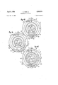
- Figs. 6-9 are radial sections taken through the lower part of Fig. 1, illustrating various alternative constructions of coupling means for coupling the diaphragm adjustment to the speed adjustment;
- Fig. 10 is a fragmentary front face view of the lower part of the shutter, further illustrating the modified construction shown in Fig. 9;
- Figs. 11 and 12 are views similar to Fig. 9 showing other modifications
- Fig. 13 is a view similar to Fig. 1 showing another embodiment of the invention.
- Fig, 14 is a view similar to Figs. 1 and 13 still another embodiment.
- Fig. 15 is a view similar to Figs. 1, l3, and 14, illustrating a further embodiment of the invention.
- a photographic shutter of the objective type or between-the-lens type which, except for the changes mentioned below, may be of any conventional construction.
- the shutter may (except for the mentioned changes) he of the construction available on the market under the trademark Compur, manufactured by the Friedrich Deckel firm in Kunststoff, Germany, such shutters being well known and widely distributed in the United States for many years past.
- Typical details of such a shutter are disclosed in U. S. Patent 1,687,123, granted October 9, 1928, for an invention of Deckel and Geiger.
- the shutter casing is indicated in general by the numeral 10.
- shutter blades 12 of any suitable number (five blades being here shown) moved to open and closed positions by the usual shutter operating mechanism such as shown in said patent.
- the driving spring of the shutter is tensioned and the other operating parts of the shutter are set in proper position ready for making an exposure, by a setting lever or tensioning lever 14, which corresponds to the setting lever 6 in said patent.
- the shutter release lever or trigger is indicated at 16 and corresponds to the release lever fill in said patent.
- the adjustment to different exposure times is effected by turning the rotatable shutter speed adjusting ring 18, which is rotatable at the front of the shutter about the optical axis of the shutter as a center, and which corresponds in general to the speed ring 63 of said patent, and which bears a speed scale or exposure time scale 2 9 corresponding to the scale 64 in said patent, cooperating with a stationary index mark or pointer 22 on the stationary front plate of the shutter.
- the shutter is also provided with an iris diaphragm or stop comprising a number of leaves 24 adjustable to various positions to vary the diameter of the light aperture, the diaphragm leaves being of conventional form and being operated by the usual rotary adjusting ring, shown but not particularly described in said patent.
- the diaphragm leaves 24 are adjusted to give an aperture or stop of varying size, by turning an adjusting ring 26 mounted at the rear of the shutter casing to turn in the usual way about the optical axis of the shutter as a center, and operatively connected to the diaphragm leaves.
- the diaphragm adjusting ring 26 has a radial arm which extends downwardly (when viewed from the front as in Fig. 1) to a point below the lower edge of the shutter casing 10, thence forwardly as at 28 past the lower edge of the casing, to a position accessible at the front of the shutter, and this arm terminates in a pointer 29 from which, in conjunction with the 7 number aperture scale 30 on the stationary front plate of the camera, may be ascertained the particular aperture or stop to which the diaphragm is set in any given position of the adjusting ring 26 and its arm 28. For example, with the particular scale 3%) shown in Fig.
- the pointer 29 is opposite the graduation 8 of scale 30, indicating that the diaphragm is set for f/ 8. If the adjusting ring 26 is turned clockwise as far as possible, the pointer 29 will be opposite the numeral 2 of the scale 30, indicating that the diaphragm leaves are open to their maximum extent, giving an aperture of f/Z. If the adjusting ring 26 is turned counterclockwise to its maximum extent, the pointer 29 comes opposite the numeral 32 of the scale 3t), indicating that the aperture or stop is closed down to f/ 32.
- the present invention approaches the problem from a basically new direction, and aims to provide the photographer with a convenient scale on the camera shutter itself, indicating various possible relationships between aperture and speed, which the photographer may use in making quick and easy adjustment of the shutter.
- this new scale is the integrated exposure value scale, or i. e. v. scale.
- the photographer determines the proper i. e. v. for the particular picture to be taken. Gnce the proper i. e. v. has been determined, the shutter may be easily adjusted by using the i. e. v. scale, and an inexperienced photographer need not particularly concern himself with separate values of speed and aperture.
- the i. e. v. scale is indicated at 34 and is engraved or otherwise formed on the shutter speed setting ring 18, so as to turn bodily with the ring 18 when the shutter speed is adjusted. It is in position to cooperate and be read with the aid of the pointer 29 connected to the diaphragm adjusting ring 23.
- This scale 34 is graduated in any suitable manner, preferably by graduations bearing consecutive numbers, such as the numbers from 1 to 17, as shown in Fig. 1.
- the shutter parts are arranged in such manner that when the shutter speed adjusting ring 33 and the diaphragm adjusting ring 26 are turned in the same direction, they produce a complementary effect on the shutter speed and the size of the aperture.
- clockwise turning of the speed ring 18 adjusts the shutter for making an exposure of shorter duration
- clockwise turning of the diaphragm ring 26 serves to open the diaphragm or stop to compensate for the shorter exposure
- counterclockwise turning of the shutter speed ring 18 will result in an exposure of longer duration
- counterclockwise turning of the ring 26 will decrease the aperttu'e to compensate for the longer exposure.
- This can be accomplished by reversing the slope of the time control cam on the ring 18, relative to the slope illustrated in said Patent No. 1,687,123.
- the time scale or shutter speed scale 2th on the speed adjusting ring 113 is preferably not graduated in the conventional manner, but rather is graduated in a uniform scale of geometrical progression from the slowest speed toward the fastest speed, each successive graduation representing an exposure time onehalf as great as that indicated by the next preceding graduation.
- the graduations may conveniently run in the series 1, 2, 4, 8, 16, 32, 64, 128, 256, and 512, with preferably uniform spaces between the successive scale markings indicated by these numerals. as understood by those skilled in the art, by the proper design of the internal mechanism of the shutter, especially the slope and position of the time control cam forming part of the ring 18.
- the scale 30, representing the extent of opening or closing of the diaphragm aperture or stop is preferably so arranged that equal increments of motion of the ring 26, at all intervals along ⁇ the scale, will result in equal proportionate increases or decreases in aperture; and also the extent of angular mo tion of the diaphragm ring 26 required to double the area of the aperture, is the same as the angular extent of motion of the speed adjusting ring 18 required to cut the exposure time in half. This is not true of conventional shutters as heretofore commonly constructed.
- the diaphragm scale is more open, with graduations spaced farther apart, at the large aperture end of the scale, and closer together or more crowded at the small aperture end of the scale.
- iris diaphragms are already known in which equal angular movements of the adjusting ring will produce equal proportionate change in the aperture area (for example, U. S. Paitent 871,654, of November 19, 1907, and British Patent 464,892, of April 27, 1937) and these principles may be employed in the construction. of the present diaphragm, to achieve equal angular movements of the adjusting ring 26 for producing equal proportionate changes, such as doubling the area of the stop or reducing the area by one-half.
- a diaphragm of the uniform scale type has never heretofore been used in combination with a shutter having a speed setting or speed control correlated with the diaphragm setting as is done in the present instance, nor in combination with an integrated exposure value scale, as in the present instance.
- the integrated exposure value is determined, as for example by using a photoelectric light meter to determine the brightness of the subject to be photographed, and by applying a suitable allowance or factor for the filter, if any, which is to be used in taking the picture and for the speed rating or exposure rating of the film which is to be used, let it be assumed that the resulting i. e. v. turns out. to be 9. Then, according to the present invention, if the pointer 29 is brought opposite the scale numeral 9 on the i. e. v. scale 34, and is kept opposite this scale numeral notwithstanding any adjustments made either in the aperture or in the shutter speed, the shutter will be properly set for taking the picture.
- the correlation of the pointer 29 to the scale 34 represents a given relationship between shutter speed and the aperture or f number, rather than an absolute value of either one of these two variables.
- either one of the two variables may be selected as desired, and if the pointer 29 is kept at the proper point on the scale 34, the other one of the two variables will automatically be accommodated to the variable whose value is first chosen.
- an exposure value of 9 on the integrated exposure value scale 34 may correspond to a speed setting of 16 (meaning of a second) and to a diaphragm setting or aperture setting of 8 (meaning 1/ 8). But it may equally well correspond to a speed setting of 32 and an aperture of 5.6, or to a speed setting of 64 and an aperture of 4, or a speed setting of 8 and an aperture of 11.
- the speed control ring 18 is turned any given number of graduation increments in one direction or the other from the illustrated setting of 16, and if the diaphragm adjusting ring 26 is turned in the same direction through an equal number of increments or steps, the
- pointer 29 will still be opposite the numeral 9 of the scale 34, and the shutter will still be properly adjusted for taking the desired picture.
- the operator is free to choose any desired shutter speed, and without mental calculations or difficulty he can easily bring the diaphragm to the proper aperture or stop for the selected shutter speed, simply by moving :the diaphragm adjusting ring 26 until the pointer 29 is opposite the proper numeral on scale 34, corresponding to the integrated exposure value as determined by the light meter or otherwise.
- the rings 18 and 26 are resiliently coupled to each other so that when either one of them is moved, the other ring is likewise automatically moved in the proper direction and to the proper extent to compensate for the movement of its companion ring.
- the arm 28 of the diaphragm adjusting ring 26 is formed with a projection or protuberance 32 (conveniently in the form of a short pin) which engages resiliently in shallow serrations or teeth 36 formed around the periphery of the speed adjusting ring 18.
- Teeth or serrations of this kind are already frequently used on shutters of this general style for enabling the user to get a better grip on the speed adjusting ring 18.
- the same teeth of conventional form as commonly used on Compur shutters will adequately serve the present purposes.
- These teeth or serrations 36 extend all the way around the periphery of the setting ring 18, although for convenience and simplicity of illustration they are shown in Fig. 1 as extending around only a fraction of the periphery.
- the arm 28 of the setting ring 26 is of metal sufiiciently resilient or springy so that the protuberance 32 can easily spring out of any one of the notches 36 and can ratchet over a series of such notches, if one of the members 18 and 26 is gently turned by hand and if there is resistance to turning the other.
- the operator to adjust the parts to any desired setting of the pointer 29 to a. selected one of the graduations 34, simply by holding one of the rings and turning the other one.
- the pin 32 will ratchet over the teeth 36 and will make a clicking noise, audi-bly calling the operators attention to the fact that the limit of travel of one of the adjusting members has been exceeded and that the setting of the parts to a preselected or predetermined integrated exposure value or total exposure factor has been disturbed.
- the i. e. v. scale is calibrated in numerals as indicated at 3d in Fig. l, but this is not necessarily the case. It may be calibrated in letters of the alphabet as indicated at 34a in Figs. 2 and 4, or in appropriate symbols as indicated at in 3 and 5. Also, variations in the teeth on the ring 18 are possible.
- the teeth 36 (Fig. l) are of sharp triangular formation and are of fairly large size, the tooth spacing being equal to the spacing of the graduations on the scale 34. But in Figs. 2 and 3 the teeth 36a and 36b, while still triangular, are smaller, there being a multiple number of teeth (for example two teeth) for each division of the scale.
- the teeth 360 are rectangular rather than triangular, while in Fig. 5 the teeth 36d are shallower and of wavy form rather than triangular with sharp corners.
- the various tooth forms may be used in any desired combination with the various forms of the scale values.
- the preferred form of the invention employs the regular grip notches 36 in the periphery of the speed setting ring 18 to form the frictional coupling engagement with the pin 32 on the diaphragm setting arm 28, this is not necessarily the case. It is entirely feasible to provide special notches or teeth for coupling the parts, other than the grip notches 36.
- the rear face of the ring 13 is provided, near its periphery, with radial notches or recesses 37 in addition to the grip notches or teeth 36.
- the resilient arm 28 of the diaphragm adjusting ring 26 is provided with a cam-shaped projection or nose 32a which engages in one or another of the notches 37, to elfect the resilient coupling between the parts.
- the end of the arm 28 extends radially outwardly a little beyond the periphery of the ring 18 to form a visible pointer or indicator which can be seen from the front of the shutter.
- FIG. 7 A slightly different form is illustrated in Fig. 7, where the coupling recesses or notches 37a are formed on the periphery of an arcuate segment 40 fixed rigidly to the rear face of the speed adjusting ring 18.
- the integrated exposure value scale or graduations are arranged on the periphery 42 of the segment 49, right beside the recesses 37a, and may be graduated in numerals, letters, or symbols, like the various forms illustrated in Figs. 1-3.
- the coupling teeth or notches are not necessarily on the periphery 42 but may be formed on any desired face of the segment, for cooperation with the appropriate nose or edge of the resilient arm 28.
- FIG. 8 Another variation of the coupling means is shown in Fig. 8, where the resilient arm 28 of the ring 26 is provided with a short pin M which engages with an arcuate series of holes 46 formed in the speed setting ring 18 in an are just above the grip teeth 36.
- the front face of the ring 18 is graduated with the integrated exposure value scale.
- the coupling is effected by a resilient arm on the diaphragm setting ring, movable to various positions on the relatively non-resilient speed setting ring 18. It is possible, however, to reverse the resilient action of the parts, placing the resilient member on the speed setting ring 38, and having it cooperate with a relatively non-resilient member on the diaphragm setting ring 26.
- a resilient arm on the diaphragm setting ring movable to various positions on the relatively non-resilient speed setting ring 18.
- the diaphragm setting ring 26, or at least the lower part thereof, for the necessary arcuate distance, is extended to be of larger diameter than the main shutter casing lit), and is provided peripherally with teeth or Of course when a supplementary segment 48 'lal notches 54.
- the i. e. v. scale 34 is marked on the front face of this portion of the ring 261, just above the notches 54.
- a resilient arm St is rigidly secured (for example, by rivets 51) to the speed setting ring 18 and extends radially downwardly a slight distance and then rcarwardly to the plane of the diaphragm setting ring 26, where the arm 50 is provided with a cam-shaped nose 52 fitting in one or another of the notches 54 on the ring 26.
- the arm or tongue 5% ⁇ is suiliciently springy so that, by exerting moderate pressure, the nose 52 may be displaced from one notch 54 to the next.
- the regular grip notches 36 are still employed on the speed setting ring 18, but they serve only the function of grip notches, without taking part in the coupling of the speed ring to tr e diaphragm ring.
- the aperture scale 30 to indicate the of the diaphragm opening may be entirely omitted for the sake of greater simplicity, although if desired the diaphragm ring 26 may be provided with a pointer arm coming around the edge of the shutter in the conventional manner to cooperate with an aperture scale 30 at a suitable point on the front of the shutter.
- the coupling reccsses or teeth 54a are not arranged directly on the diaphragm adjusting ring 26, but are formed on an arcuate segment all which is rigidly connected to the ring 26.
- the resilient arm Gil is connected to the speed setting ring it; and has a nose or cam portion 52 cooperating with the coupling recesses 54a.
- the integrated exposure value scale is placed on the periphery 62 of the arcuate segment 66.
- the construction represents essentially a reversal of the construction shown in Fig. 7, the annular segment and the resilient arm simply being reversed relative to the respective speed setting ring 13 and diaphragm setting ring 26.
- the coupling recesses or teeth 54a be placed on the outer arcuate surface as illustrated, as they can be placed on the inner arcuate surface or the forward surface of the segment 60.
- the diaphragm setting ring 26 is provided with a rearwardly extending flange in which are formed holes 66.
- the resilient arm 5th mounted on the speed setting ring 18 provided with a pin 64 which extends into one or an other of the holes 66, depending on the setting desired.
- the exposure value scale in this instance may be placed on the rearwardly extending flange or periphery in which the holes are formed.
- the shutter speed adjusting member should be set for any particular diaphragm aperture selected. This is of great help especially to the beginner, and is of advantage even to a more experienced photographer since it avoids the. need for either mental calculation on the one hand, or consultation .of extraneous reference material on the other hand, as might be necessary if the photographer desires to change the diaphragm aperture, for example, from f/4 to f/ 16 and then wonders just how far to change the speed setting of the shutter in order to compensate for this change in diaphragm aperture.
- FIG. 13 A construction having the advantages of the present invention except for the physical coupling between the speed setting mechanism and diaphragm setting mechanism, is illustrated in Fig. 13. This construction may be the same as the construction shown in Fig. 1 except that the coupling pin or nose 32 is omitted.
- the respective scales 211, 3d, and 34 are the same as in Fig. 1.
- the i. e. v. scale has been placed on the speed setting ring 18, while in Figs. 9-12 the scale has been placed on the aperture adjusting member, but in a location rearwardly of the front face of the shutter.
- this scale it is equally possible to place this scale on the aperture adjusting member at the front of the shutter, as in Fig. 14, by extending the aperture setting member forwardly at the bottom of the shutter and providing it with a segmental flange 28a on which the i. e. v. scale 340 is placed for cooperation with an index mark 140 placed on the speed adjustment ring 18.
- An index mark such as the nose 28b on the aperture setting member 28a cooperates with the aperture scale 30 formed on the stationary front plate of the shutter, to show at what aperture the shutter diaphragm is set, at any given time.
- This construction shown in Fig. 14 is equally possible with or without the use of physical coupling between the speed adjusting member and the diaphragm adjusting member.
- the speed graduations and the aperture graduations are both graduated linearly according to a geometrical progression, but this is not necessarily the case. So long as the actual effect of the speed control cams on the ring 18 is to produce a change in speed correlated with the change in aperture produced by an equal extent of turning movement of the diaphragm adjusting member 26, it is apparent that the i. e. v. scale 34 may be advantageously used, and that the speed adjusting member and diaphragm adjusting member may be physically coupled together, quite regardless of the exact graduations or numerals which appear on the scale 20. Since it is the i. e. v.
- the speed scale 20 which is used to correlate the shutter speed to the diaphragm aperture and since the speed rat- It) ing numerals of the scale 20 are not used for this purpose but only to give the photographer an indication of shutter speed in case he may wish to photograph a moving object, it is apparent that the speed scale 20 may be graduated, if desired, in the more familiar manner of arbitrary numbers such as 1, 2, 5, 10, 25, 50, etc., so long as the speed control cam is nevertheless of the proper shape to change the speed of the shutter accord ing to a geometrical progression correlated with that of the aperture adjusting member.
- FIG. 15 An example of the use .of the i. e. v. scale on a shutter which may have disconformity between the speed setting and the aperture setting means is illustrated in Fig. 15.
- an integrated exposure value scale 34 is placed on the speed setting ring 18 just as in the case of the embodiment of Fig. 1.
- the stationary front plate of the shutter has an aperture scale 30 like the scale 30 in Fig. 1, graduated in proper correlation to the speed adjustment changes produced by turning the speed ring 18.
- a ring 141 is rotatably supported on the front lens tube 142 of the shutter casing, and has a radial guide arm or reading arm 144 provided with an elongated radial sight window 146 through which may be simultaneously read one value from the scale 34 and one value from the scale 30.
- a second diaphragm aperture scale 30b graduated in accordance with the actual aperture changes produced by turning the ring 26, is arranged at another suitable location on the stationary front plate of the shutter, to cooperate with the arm 28 on the diaphragm adjusting ring 26.
- the proper integrated exposure value is obtained, as before, by means of a light meterv or by visual inspection and estimate. Let it be assumed that the exposure value is determined as 9. The photographer then selects either the desired shutter speed or the desired aperture for the exposure to be made. Assuming that he selects a shutter speed of of a second, he sets the speed control ring 18 to bring the numeral 16 opposite the index mark 22, as
- the diaphragm aperture must be set at 8. Then the diaphragm is adjusted to aperture 8 by moving the arm 28 relative to the aperture scale 30b.
- the photographer first selects the aperture, deciding that he wants to take the picture with an aperture of 8, he moves the arm 28 to this aperture setting on the scale 30b, then moves the arm 144 until the aperture 8 of the scale 30 appears through the window 146. Then the ring 18 is turned until the i. e. v. graduation 9 of the scale 34 appears through the window 146, which brings the speed setting to the proper 11 correlation with the aperture setting, all without the need of any mental calculations by the photographer and without the need for consulting any extraneous reference material other than what is available right on the shutter itself.
- the shutter may be of a kind or style in which the speed scale 20 and the aperture scale 3% are non-linear and are in complete disconformity to each other, perhaps even being arranged in reversed or counter directions instead of in correlated directions.
- the i. e. v. scale could be arranged on the diaphragm setting member rather than on the speed setting member, just as was done in the construction of Fig. 14, and in that event a shutter speed scale would be placed on the stationary front plate of the shutter, to be read in conjunction with the i. e. v. scale, by means of the radial reading arm or guide.
- the diaphragm aperture is expressed as an f number, the 1 number is in inverse proportion to the diameter of the aperture, not its area, and since the area changes in proportion to the square of the diameter, it follows that the area of the aperture will vary in inverse proportion to the square of the f nurnber.
- f/S a proper duration of exposure is determined when the diaphragm aperture is set at f/S, a readjustment of the diaphragm aperture to f/ 16 will require that the duration of exposure be not merely doubled, but
- a photographic shutter comprising an annular housing having an exposure aperture therethrough, a stationary front member encircling said aperture, a shutter speed adjusting member of annular form rotatably mounted on said housing and partly underlying said stationary front member and partly projecting radially outwardly beyond said stationary front member to an accessible peripheral for manual grasping and turning, a single reference point marked on said stationary front member, a shutter speed scale marked on said speed adjusting member in position to move past said reference point as said speed adjusting member is turned relative to said stationary from member and to be read in conjunction with said reference point, a diaphragm aperture adjusting member of annular form rotatably mounted on said housing approximately at therear thereof and having an arm extending forwardly past a circumferential edge of said housing, a portion of said arm being resilient, said arm near its forward end engaging in depressions in said shutter speed adjusting member at a portion of the periphery thereof angularly spaced from said shutter speed scale with sufiicient force to couple said aperture adjusting member frictionally to said speed adjusting
Landscapes
- Physics & Mathematics (AREA)
- General Physics & Mathematics (AREA)
- Exposure Control For Cameras (AREA)
Applications Claiming Priority (1)
| Application Number | Priority Date | Filing Date | Title |
|---|---|---|---|
| DE744962X | 1952-11-07 |
Publications (1)
| Publication Number | Publication Date |
|---|---|
| US2829574A true US2829574A (en) | 1958-04-08 |
Family
ID=6648182
Family Applications (1)
| Application Number | Title | Priority Date | Filing Date |
|---|---|---|---|
| US389775A Expired - Lifetime US2829574A (en) | 1952-11-07 | 1953-11-02 | Photographic shutter |
Country Status (4)
| Country | Link |
|---|---|
| US (1) | US2829574A (da) |
| CH (1) | CH317147A (da) |
| DK (1) | DK84249C (da) |
| GB (1) | GB744962A (da) |
Cited By (11)
| Publication number | Priority date | Publication date | Assignee | Title |
|---|---|---|---|---|
| US2887940A (en) * | 1954-05-19 | 1959-05-26 | Hans Deckel | Photographic shutter |
| US2929308A (en) * | 1956-01-12 | 1960-03-22 | Voigtlaender Ag | Photographic camera having exchangeable objectives |
| US2959113A (en) * | 1956-03-28 | 1960-11-08 | Chiyoda Kogaku Seiko Kabushiki | Apparatus for coordinating camera shutter speed, iris opening and light value |
| US3021770A (en) * | 1958-09-29 | 1962-02-20 | Polaroid Corp | Photographic shutter |
| US3039376A (en) * | 1957-02-02 | 1962-06-19 | Voigtlaender Ag | Photographic camera provided with means for adjustment of the light value |
| US3044375A (en) * | 1960-04-01 | 1962-07-17 | Leitz Ernst Gmbh | Camera with built-in exposure meter |
| US3089397A (en) * | 1956-02-23 | 1963-05-14 | Gauthier Gmbh A | Photographic intra-lens shutter and coupled exposure meter |
| US3344727A (en) * | 1963-08-28 | 1967-10-03 | Gauthier Gmbh A | Photographic camera with distance and diaphragm aperture setting members |
| US3363529A (en) * | 1964-04-18 | 1968-01-16 | Prontor Werk Gauthier Gmbh | Photographic camera with channelcorrelated scale |
| US3685424A (en) * | 1970-08-04 | 1972-08-22 | Tektronix Inc | Camera computer apparatus |
| US11498396B1 (en) | 2018-12-24 | 2022-11-15 | Robert N. Justice | Viewing port |
Families Citing this family (2)
| Publication number | Priority date | Publication date | Assignee | Title |
|---|---|---|---|---|
| US2926589A (en) * | 1955-06-01 | 1960-03-01 | Compur Werk Friedrich Deckel | Photographic camera structure |
| US3049064A (en) * | 1956-11-24 | 1962-08-14 | Compur Werk Friedrich Deckel | Photographic shutter |
Citations (7)
| Publication number | Priority date | Publication date | Assignee | Title |
|---|---|---|---|---|
| GB191407787A (en) * | 1913-04-16 | 1900-01-01 | Lester Cooke Hereward | Improvements in Photographic Shutters. |
| DE303088C (da) * | 1900-01-01 | |||
| US1543208A (en) * | 1919-08-14 | 1925-06-23 | Fairchild Sherman Mills | Exposure device for photographic cameras |
| US1623998A (en) * | 1914-03-27 | 1927-04-12 | Cooke Patents Inc | Photographic shutter |
| US2590161A (en) * | 1948-07-01 | 1952-03-25 | Dennis B Dorsey | Camera exposure control |
| US2596328A (en) * | 1948-08-18 | 1952-05-13 | Dennis B Dorsey | Camera exposure control |
| FR1028877A (fr) * | 1949-12-27 | 1953-05-28 | Dispositif pour régler les valeurs déterminant l'exposition sur les appareils photographiques |
-
1953
- 1953-08-26 DK DK276353AA patent/DK84249C/da active
- 1953-09-21 CH CH317147D patent/CH317147A/de unknown
- 1953-11-02 US US389775A patent/US2829574A/en not_active Expired - Lifetime
- 1953-11-06 GB GB30763/53A patent/GB744962A/en not_active Expired
Patent Citations (7)
| Publication number | Priority date | Publication date | Assignee | Title |
|---|---|---|---|---|
| DE303088C (da) * | 1900-01-01 | |||
| GB191407787A (en) * | 1913-04-16 | 1900-01-01 | Lester Cooke Hereward | Improvements in Photographic Shutters. |
| US1623998A (en) * | 1914-03-27 | 1927-04-12 | Cooke Patents Inc | Photographic shutter |
| US1543208A (en) * | 1919-08-14 | 1925-06-23 | Fairchild Sherman Mills | Exposure device for photographic cameras |
| US2590161A (en) * | 1948-07-01 | 1952-03-25 | Dennis B Dorsey | Camera exposure control |
| US2596328A (en) * | 1948-08-18 | 1952-05-13 | Dennis B Dorsey | Camera exposure control |
| FR1028877A (fr) * | 1949-12-27 | 1953-05-28 | Dispositif pour régler les valeurs déterminant l'exposition sur les appareils photographiques |
Cited By (11)
| Publication number | Priority date | Publication date | Assignee | Title |
|---|---|---|---|---|
| US2887940A (en) * | 1954-05-19 | 1959-05-26 | Hans Deckel | Photographic shutter |
| US2929308A (en) * | 1956-01-12 | 1960-03-22 | Voigtlaender Ag | Photographic camera having exchangeable objectives |
| US3089397A (en) * | 1956-02-23 | 1963-05-14 | Gauthier Gmbh A | Photographic intra-lens shutter and coupled exposure meter |
| US2959113A (en) * | 1956-03-28 | 1960-11-08 | Chiyoda Kogaku Seiko Kabushiki | Apparatus for coordinating camera shutter speed, iris opening and light value |
| US3039376A (en) * | 1957-02-02 | 1962-06-19 | Voigtlaender Ag | Photographic camera provided with means for adjustment of the light value |
| US3021770A (en) * | 1958-09-29 | 1962-02-20 | Polaroid Corp | Photographic shutter |
| US3044375A (en) * | 1960-04-01 | 1962-07-17 | Leitz Ernst Gmbh | Camera with built-in exposure meter |
| US3344727A (en) * | 1963-08-28 | 1967-10-03 | Gauthier Gmbh A | Photographic camera with distance and diaphragm aperture setting members |
| US3363529A (en) * | 1964-04-18 | 1968-01-16 | Prontor Werk Gauthier Gmbh | Photographic camera with channelcorrelated scale |
| US3685424A (en) * | 1970-08-04 | 1972-08-22 | Tektronix Inc | Camera computer apparatus |
| US11498396B1 (en) | 2018-12-24 | 2022-11-15 | Robert N. Justice | Viewing port |
Also Published As
| Publication number | Publication date |
|---|---|
| DK84249C (da) | 1958-01-20 |
| GB744962A (en) | 1956-02-15 |
| CH317147A (de) | 1956-11-15 |
Similar Documents
| Publication | Publication Date | Title |
|---|---|---|
| US2829574A (en) | Photographic shutter | |
| US2868095A (en) | Photographic camera construction | |
| US1623998A (en) | Photographic shutter | |
| US2278338A (en) | Photoelectric apparatus for cameras | |
| US2990758A (en) | Photographic cameras | |
| US2527106A (en) | Depth of field indicator | |
| US2590161A (en) | Camera exposure control | |
| US2917983A (en) | Setting mechanism for photographic camera exposures | |
| US2241020A (en) | Photographic camera | |
| US4045807A (en) | Automatic exposure control apparatus which prevents simultaneous diaphragm and shutter speed preselection | |
| US2849936A (en) | Photographic camera with exposure meter | |
| US2960921A (en) | Photographic camera | |
| US2911897A (en) | Mechanism for setting photographic exposure values | |
| US2878738A (en) | Preselector for optical diaphragms | |
| US3427946A (en) | Single lens reflex cameras | |
| US2965011A (en) | Diaphragm setting device for a photographic camera | |
| US2949836A (en) | Depth-of-field indicator for photographic objectives | |
| US2936690A (en) | Photographic camera | |
| US2889761A (en) | Photographic shutter with interchangeable lens | |
| US2279723A (en) | Photoelectric exposure determining | |
| US3318214A (en) | Photographic camera | |
| US3505942A (en) | Manually set objective for a photographic camera | |
| US2887939A (en) | Photographic exposure controlling apparatus | |
| US3538823A (en) | Exposure control for photographic cameras | |
| US2926584A (en) | Photographic camera and shutter construction |