US282552A - Magazine-gun - Google Patents
Magazine-gun Download PDFInfo
- Publication number
- US282552A US282552A US282552DA US282552A US 282552 A US282552 A US 282552A US 282552D A US282552D A US 282552DA US 282552 A US282552 A US 282552A
- Authority
- US
- United States
- Prior art keywords
- magazine
- barrels
- revolving
- cylinder
- gun
- Prior art date
- Legal status (The legal status is an assumption and is not a legal conclusion. Google has not performed a legal analysis and makes no representation as to the accuracy of the status listed.)
- Expired - Lifetime
Links
- 238000010276 construction Methods 0.000 description 7
- 238000010304 firing Methods 0.000 description 3
- 238000010411 cooking Methods 0.000 description 2
- 230000004048 modification Effects 0.000 description 2
- 238000012986 modification Methods 0.000 description 2
- 241001052209 Cylinder Species 0.000 description 1
- 238000007599 discharging Methods 0.000 description 1
- 239000002184 metal Substances 0.000 description 1
- 230000035515 penetration Effects 0.000 description 1
- IZUPBVBPLAPZRR-UHFFFAOYSA-N pentachlorophenol Chemical compound OC1=C(Cl)C(Cl)=C(Cl)C(Cl)=C1Cl IZUPBVBPLAPZRR-UHFFFAOYSA-N 0.000 description 1
Images
Classifications
-
- F—MECHANICAL ENGINEERING; LIGHTING; HEATING; WEAPONS; BLASTING
- F41—WEAPONS
- F41A—FUNCTIONAL FEATURES OR DETAILS COMMON TO BOTH SMALLARMS AND ORDNANCE, e.g. CANNONS; MOUNTINGS FOR SMALLARMS OR ORDNANCE
- F41A9/00—Feeding or loading of ammunition; Magazines; Guiding means for the extracting of cartridges
- F41A9/01—Feeding of unbelted ammunition
- F41A9/24—Feeding of unbelted ammunition using a movable magazine or clip as feeding element
- F41A9/26—Feeding of unbelted ammunition using a movable magazine or clip as feeding element using a revolving drum magazine
- F41A9/27—Feeding of unbelted ammunition using a movable magazine or clip as feeding element using a revolving drum magazine in revolver-type guns
Definitions
- the subject of this invention is an arm constructed with a many-chambered revolving cylinder or barrels, loaded from an automatic :0 magazine or feeder by means of aplunger, and having a shell-extractor of novel construction, consisting of a hook or catch working in a circular groove in the rear of the revolving cyl inder or barrels, and retracted by gearing connecting it with the loading-plunger, as hereinafter described.
- the feed-magazine is provided with reserve-chambers, which, in succession, discharge their contents automatically into the feed-chamber, so that forty rounds may be contained within compact space, and the cartridges may be delivered successively to the loading mechanism without lodging or obstruction.
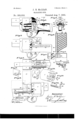
- Sheet 1 illustrates the application of my invention to a rifle; but the invention may also be applied to pistols, and likewise to artillery and heavy guns.
- Figure 1 is a sectional side elevation, showing the operating mechanism.
- Fig. 2 is a sectional side elevation, showing the operating mechanism.
- 0 is a side elevation with part of the revolving cylinder broken away to show the cart ridge-shell extractor.
- Fig. 3 is a plan or top View of the operating parts.
- Fig. 4. is an elevation of the opposite side from Fig. 2, show- 3 5 ing the magazine and its accessories.
- Fig. 5 is a transverse section on the line 5 5, Fig. 1.
- Fig. 6 is a vertical section of the magazine.
- Fig. 7 is a top View of the same partly broken away.
- Fig. 8 is a partial vertical section of the magazine on a larger scale to illustrate more clearly the construction and operation of the trap doors or valves which pass the cartridges from the reserve-chambers to the feeding-chamber, as hereinafter described.
- FIG. 9 is an enlarged back view of the lower end of the magazine, showing the position of the retaining-spring when the magazine is in prostrate position or is detached from the gun.
- Fig.' 10 is a rear view of the same in position for use.
- Fig. 11 is a perspective view of a portion of the charging-plunger.
- Fig. 12 is a perspective view of the revolving cylinder.
- Fig. 13 is a detached perspective viewof a dog for turning the cylinder.
- Fig. 11 is aperspective view of the cartridge-shell extractor and cylinder-stop.
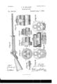
- Sheet 2 represents a modification under which my invention is embodied in a gun, having a cluster of barrels revolving bodily instead of a cylinder revolving in rear of a stationary barrel, as in the former illustration.
- Fig. 15 is a side elevation of the said gun.
- Fig. 16 is a plan of the breech portion thereof.
- Fig. 17 is a rear elevation of the buttring and barrels on a larger scale.
- Fig. 18 isa side elevation of the said butt-ring and the rear portion of the barrels.
- Fig. 19 is avertical longitudinal section of the same.
- Fig. 20 is a transverse section on the line 20 20, Fig. 15, looking backward.
- Fig. 15 is a side elevation of the said gun.
- Fig. 16 is a plan of the breech portion thereof.
- Fig. 17 is a rear elevation of the buttring and barrels on a larger scale.
- Fig. 18 is a side elevation of
- FIG. 21 is a side elevation of the central portion of the barrels with their containing-ring and the front portion of the stock in section.
- Figs. 22 and 23 are respectively a transverse section and a side elevation, illustrating a modification in construction of the parts shown in Figs. 20 7 5 and 21.
- Saidtrigger is provided with a rigid arm, 7, bearing on an arm, 8, pivoted at 9 to a hammer, 10, and thrown out by means of a spring, 11, an anti-friction roller being mounted in the lower end of the arm 8 to receive the bearing of the rigid trigger-arm 7 12 represents a dog hinged to the cockingarm 8 and thrown out by a spring, 13. Said dog engages with the ratchet-teeth 14 in the 5 rear of the cylinder 1 for revolving the same.
- the firingtrigger is shown at 15, and a firingpin of common construction at 16.
- My improved magazine is shown at 17 and in the detailed views Figs. 6, 7, and 8. It is constructed with a vertical feeding-chamber
- This magazine may be constructed, 'mainly, of paper, or of simple sheet metal, and may readily be adapted to contain forty cartridges.
- the magazine is pivoted at 21 (see Fig. 4) by one of its lower corners to the top of the gunstock directly in rear of the revolving cylinder 1, and in position to bring the vertical feeding-chamber 18 directly over the loading-trough 22. This mode of engaging themagazine admits of its'being tipped back into prostrate position, -as indicated by dotted lines in Fig. 4.
- a spring-catch, 23, projecting beneath the bottom of the vertical feed-chamber 18, so as to prevent the escape of cartridges when 7 the magazine is removed from the gun or is is retracted bya spring, 28.
- This is formed in front with an upwardly-projecting rigid arm, 32, terminating in a hook, 33, which fits in a circular groove, 34, extending around the rear face of the cylinder 1 in a circle coincident with the centers of the charge-chambers.
- the hook 33 is flanked by shoulders 35, which rest against the rear face of the revolving cylinder and limit the penetration of the hook 33 into the groove 34, and serve also, by contact with the projecting flanged bases of the cartridge-shells, to arrest the rotation of the cylinder at the proper points for firing.
- the cartridges are introduced into the magazine 17 from the rear, a door, 36, for this purpose being shown in Fig. 7, hinged at 37, and held in closed position by a catch, 38.
- the opening of this door exposes all the chambers 18 and 19 simultaneously.
- the ring rests and turns on an anti-friction ball, 43, and bears backward against a shoulder, 44, in the 'stock 2, and in front against a shoulder, 45, of less depth, being confined in the seat thus provided by a sliding segmental catch, 46, secured by a screw, 47.
- the said catch 46 fits within the annular groove in the forward edge of the ring 42, so as to permit the free rotation of said ring, together with the barrels, as already described.
- I employ a band, 48, passing either partially or entirely around the barrels and stock, and secured to the stock by any suitble means as, for example, by screws 49the said band fitting within a peripherial groove in the ring 42, as clearly shown in Figs. 22 and 23, and the ball 43 being used as before.
- the loading magazine and plunger. and the cartridge -'extractor are used as before, the rear face of the butt-ring 39 being provided with the annular groove 34 to receive the hook 33 of the cartridge-extractor and permite it to take an effective grip upon the flange of the shell which is presented to it.
- a revolving cha1nbered cylinder or a revolving cluster of barrels provided with a circular series of ratchetteeth, 14, in combination with a cylinder or barrel operating and cooking and firing mechanism, consisting of a pivoted trigger-arm, 4, formed with a tappetarm, 7, a hammer, 9, carrying a pivoted arm, 8, engaged by said tap pet-arm, a dog or pawl, 12, pivoted upon the said arm 8 and engaging with the ratchet-teeth 14, and a firing-trigger, 15, and suitable springs acting upon the said parts, substantially as described.
- a retracting-spring and a hand lug or lever
- an extractor provided with a rack and a shouldered hook
- an interposed gear-pinion engaging with the said racks, of a feeding-hopper composed of a main vertical feed-chamber, communicating at its lower end with the said loading-trough, and auxiliary chambers open in g into said main chamber, and provided with attachments controlled by the contents of the main chamber, substantially as and for the purposes described.
Landscapes
- Engineering & Computer Science (AREA)
- General Engineering & Computer Science (AREA)
- Toys (AREA)
- Portable Nailing Machines And Staplers (AREA)
Description
(No Model.) 2 Sheets-Sheet 1.
J. H. MGLEAN.
MAGAZINE GUN.
No. 282,552. Patented Aug. '7, 1888.
A'psi: XW 2 l N PETERS Photo-Lithographer, W1shmg90n. u c.
2 S heetsSheet 2. J. H. MoLEAN.
MAGAZINE GUN.
N Modl.)
Patented Aug. '7, 1883.
itgegg a UNITED STATES PATENT @EFICE.
JAMES H. IVICLEAN, OF ST. LOUIS, MISSOURI.
MAGAZINE-GUN.
SPECIFICATION forming part of Letters Patent No. 282,552, dated August '7, 1883.
Application filed October 26, 18:11. (No model.)
To ail whom it may concern:
Be it known that 1, JAMES HENRY MGLEAN, a citizen of the United States, residing at St. Louis, in the State of Missouri,- have invented certain Improvements in Magazine Fire-Arms,
of which the following is a specification.
The subject of this invention is an arm constructed with a many-chambered revolving cylinder or barrels, loaded from an automatic :0 magazine or feeder by means of aplunger, and having a shell-extractor of novel construction, consisting of a hook or catch working in a circular groove in the rear of the revolving cyl inder or barrels, and retracted by gearing connecting it with the loading-plunger, as hereinafter described. The feed-magazine is provided with reserve-chambers, which, in succession, discharge their contents automatically into the feed-chamber, so that forty rounds may be contained within compact space, and the cartridges may be delivered successively to the loading mechanism without lodging or obstruction.
In the accompanying drawings, Sheet 1 illustrates the application of my invention to a rifle; but the invention may also be applied to pistols, and likewise to artillery and heavy guns. Figure 1 is a sectional side elevation, showing the operating mechanism. Fig. 2
0 is a side elevation with part of the revolving cylinder broken away to show the cart ridge-shell extractor. Fig. 3 is a plan or top View of the operating parts. Fig. 4. is an elevation of the opposite side from Fig. 2, show- 3 5 ing the magazine and its accessories. Fig. 5 is a transverse section on the line 5 5, Fig. 1. Fig. 6 is a vertical section of the magazine. Fig. 7 is a top View of the same partly broken away. Fig. 8 is a partial vertical section of the magazine on a larger scale to illustrate more clearly the construction and operation of the trap doors or valves which pass the cartridges from the reserve-chambers to the feeding-chamber, as hereinafter described. Fig.
9 is an enlarged back view of the lower end of the magazine, showing the position of the retaining-spring when the magazine is in prostrate position or is detached from the gun. Fig.' 10 is a rear view of the same in position for use. Fig. 11 is a perspective view of a portion of the charging-plunger. Fig. 12 is a perspective view of the revolving cylinder. Fig. 13 is a detached perspective viewof a dog for turning the cylinder. Fig. 11 is aperspective view of the cartridge-shell extractor and cylinder-stop. Sheet 2 represents a modification under which my invention is embodied in a gun, having a cluster of barrels revolving bodily instead of a cylinder revolving in rear of a stationary barrel, as in the former illustration. Fig. 15 is a side elevation of the said gun. Fig. 16 is a plan of the breech portion thereof. Fig. 17 is a rear elevation of the buttring and barrels on a larger scale. Fig. 18 isa side elevation of the said butt-ring and the rear portion of the barrels. Fig. 19 is avertical longitudinal section of the same. Fig. 20 is a transverse section on the line 20 20, Fig. 15, looking backward. Fig. 21 is a side elevation of the central portion of the barrels with their containing-ring and the front portion of the stock in section. Figs. 22 and 23 are respectively a transverse section and a side elevation, illustrating a modification in construction of the parts shown in Figs. 20 7 5 and 21.
1 represents a revolving cylinder having any desirable number of chambers (three or more) and turning within the breech-frame 2, to which is fixed the barrel 3, so that the succcssive chambers of the cylinder may be brought into firing position in the rear of said barrel in customary manner. For revolving the chambered cylinder when cooking the piece I have shown a trigger, l, fulcrumed at 5, and retracted by a spring, 6. Saidtrigger is provided with a rigid arm, 7, bearing on an arm, 8, pivoted at 9 to a hammer, 10, and thrown out by means of a spring, 11, an anti-friction roller being mounted in the lower end of the arm 8 to receive the bearing of the rigid trigger-arm 7 12 represents a dog hinged to the cockingarm 8 and thrown out by a spring, 13. Said dog engages with the ratchet-teeth 14 in the 5 rear of the cylinder 1 for revolving the same. The firingtrigger is shown at 15, and a firingpin of common construction at 16.
My improved magazine is shown at 17 and in the detailed views Figs. 6, 7, and 8. It is constructed with a vertical feeding-chamber,
cartridges in the reserve-chamber or by means of a spring, and permit the reserve-cartridges to slip'or roll into the feeding-chamber, and so on with all the inclined reserve-chambers successively from the top. An automatic and continuous feed of all the cartridges in the magazine is thus effected without obstruction orchoking. This magazine may be constructed, 'mainly, of paper, or of simple sheet metal, and may readily be adapted to contain forty cartridges. The magazineis pivoted at 21 (see Fig. 4) by one of its lower corners to the top of the gunstock directly in rear of the revolving cylinder 1, and in position to bring the vertical feeding-chamber 18 directly over the loading-trough 22. This mode of engaging themagazine admits of its'being tipped back into prostrate position, -as indicated by dotted lines in Fig. 4.
To the inclined bottom of the magazine is fixed a spring-catch, 23, projecting beneath the bottom of the vertical feed-chamber 18, so as to prevent the escape of cartridges when 7 the magazine is removed from the gun or is is retracted bya spring, 28.
in the prostrate position shown in dotted lines, Fig. 4. This position of the spring-catch is shown in Fig. 9. The cartridges are shown in the various figures at 24.
WVhen the magazine is erected in feeding position the spring-catch 23 engages beneath a lug, 25, on the side of the feeding-trough 22, as illustrated in Fig. 10, said spring-catch bein g thus removed from the bottom of the magazinc, and serving to hold the magazine in place while permitting the cartridges to feed successively into the trough 22. The bottom cartridge is now directly in front of the chargeplunger 26, the construction of which is shown in the. detached view, Fig. 11. It is provided with a downwardly-projecting handle, 27, and 7 On its inner side is formed a rack, 29, Fig. 11, gearing with a pinion, 30, Figs. 1,3, and 5, the opposite side of which meshes with the sliding stem or stock of my cartridge-extractor 31. This is formed in front with an upwardly-projecting rigid arm, 32, terminating in a hook, 33, which fits in a circular groove, 34, extending around the rear face of the cylinder 1 in a circle coincident with the centers of the charge-chambers. The hook 33 is flanked by shoulders 35, which rest against the rear face of the revolving cylinder and limit the penetration of the hook 33 into the groove 34, and serve also, by contact with the projecting flanged bases of the cartridge-shells, to arrest the rotation of the cylinder at the proper points for firing. The
hook 33 at the same time engagesbeneath theflanged cartridge-shell in readiness for drawing out the said shell when the extractor 31 32 33 is retracted by the movement of the load ingplunger 26, as before described.
The cartridges are introduced into the magazine 17 from the rear, a door, 36, for this purpose being shown in Fig. 7, hinged at 37, and held in closed position by a catch, 38. The opening of this door exposes all the chambers 18 and 19 simultaneously.
lhave shown, for the purpose of illustration, a cylinder with six load-chambers. A modified form of cylinder may be used with but three chambers. If preferred, the cylinder mayturn on a fixed pintle, and may be rotated by teeth in its periphery, according to another well-known mode.
In the modified form of gun (shown in Sheet 2) three barrels, 3 3 3, are shown in a connected revolving cluster, instead of a revolving cylinder with a stationary barrel. These barrels are secured together at their rear ends by being screwed into a revolving breech-ring or band, 39, said band being provided with a pivot, 40, on which the barrels turn, and having notches 41 for the revolution of the barrel by the means already described. Located at a convenient point on the barrels, so that they may be as nearly balanced between butt and muzzle as practicable, is a second ring, 42, to hold the barrels firmly together, and also to hold them in position in the stock 2. The ring rests and turns on an anti-friction ball, 43, and bears backward against a shoulder, 44, in the 'stock 2, and in front against a shoulder, 45, of less depth, being confined in the seat thus provided by a sliding segmental catch, 46, secured by a screw, 47. The said catch 46 fits within the annular groove in the forward edge of the ring 42, so as to permit the free rotation of said ring, together with the barrels, as already described.
In the modified construction (shown in Figs. 22 and 23) I employ a band, 48, passing either partially or entirely around the barrels and stock, and secured to the stock by any suitble means as, for example, by screws 49the said band fitting within a peripherial groove in the ring 42, as clearly shown in Figs. 22 and 23, and the ball 43 being used as before. The loading magazine and plunger. and the cartridge -'extractor are used as before, the rear face of the butt-ring 39 being provided with the annular groove 34 to receive the hook 33 of the cartridge-extractor and permite it to take an effective grip upon the flange of the shell which is presented to it.
By a gun of this construction lightness will be obtained, as the barrels are separate and distinct from each other, and yetheld firmly together by means of the rings and bands 39 and 42.
I am aware that it is not broadly new in'revolving fire-arms to employ the mechanism which turns the barrels or revolving cylinder to operate the loading and discharging mechanism, and also to remove the shells of the eartridges after they are fired, or to arrange in connection with such a firearm an inclined feedingtrough for the reception and dispe1ising of fresh cartridges.
Having thus described my invention, the following is what I claim as new therein and desire to secure by Letters Patent 1. In a magazine fire-arm, a revolving cha1nbered cylinder or a revolving cluster of barrels provided with a circular series of ratchetteeth, 14, in combination with a cylinder or barrel operating and cooking and firing mechanism, consisting of a pivoted trigger-arm, 4, formed with a tappetarm, 7, a hammer, 9, carrying a pivoted arm, 8, engaged by said tap pet-arm, a dog or pawl, 12, pivoted upon the said arm 8 and engaging with the ratchet-teeth 14, and a firing-trigger, 15, and suitable springs acting upon the said parts, substantially as described.
2. In a magazine fire-arm, the combination, with a loading-plunger provided with a rack, a retracting-spring and a hand-lever, and an extractor provided with a rack and a shouldered hook for engaging a flanged cartridgeshell, of a geared pini'on interposed between the loading-plunger and the extractor and engaging with the racks thereof, whereby the loading and extracting shall be effected simultaneously by hand manipulation of the load ing-plunger.
3. The combination, with a series of revolving load-chambers, a ratchet-ring moving therewith, a circular groove intersecting said load-chambers, and mechanism, substantially as described, for actuating said revolving loadchambers, of aloading-plunger provided with a rack, a retracting-spring and a hand-lever, an extractor provided with a rack and a shouldered hook working in the said circular groove and engaging with the flanged cartridge-shells in said loadi-ng-chambers, and a gear-pinion interposed between the said plunger and extractor and engaging with the racks thereof, substantially as and for the purposes set forth.
4. The combination, with a series of revolving load-chambers, provided with a circular groove intersecting their axes, and a ratchet.
in the feed-trough, and provided with a rack,
a retracting-spring, and a hand lug or lever, an extractor provided with a rack and a shouldered hook, and an interposed gear-pinion engaging with the said racks, of a feeding-hopper composed of a main vertical feed-chamber, communicating at its lower end with the said loading-trough, and auxiliary chambers open in g into said main chamber, and provided with attachments controlled by the contents of the main chamber, substantially as and for the purposes described.
5. The combination of the clustered barrels, and the binding and balancing ring turning upon an anti-frietion ball in the stock, and secured in position by means of shoulders and a sliding segmental catch in such a manner as to permit the free rotation of the ring and the removal of the barrels, with a second ring provided with a notched pivot, substantially as and for the purposes set forth.
6. The combination of the flanged binding-ring 42, moving upon an anti-friction ball in the gunbody 2, with'the said gun-body carrying an adjustable catch or stop, 46 47, substantially as and for the purposes specified.
7. The combination, with the clustered barrels 3 and suitable binding'rings therefor, substantially as described, of a disk, 39, for hold ing said barrels, and provided with a ratchetring, 40 41, substantially as and for the pnu poses specified.
JAMES HENRY MPLEAN.
Vitnesses:
JAS. MILLAN, \V. E. LEFFERTY.
Publications (1)
| Publication Number | Publication Date |
|---|---|
| US282552A true US282552A (en) | 1883-08-07 |
Family
ID=2351761
Family Applications (1)
| Application Number | Title | Priority Date | Filing Date |
|---|---|---|---|
| US282552D Expired - Lifetime US282552A (en) | Magazine-gun |
Country Status (1)
| Country | Link |
|---|---|
| US (1) | US282552A (en) |
-
0
- US US282552D patent/US282552A/en not_active Expired - Lifetime
Similar Documents
| Publication | Publication Date | Title |
|---|---|---|
| US10180296B2 (en) | Firearm adapted to use linked ammunition and kit for converting magazine-fed firearm to same | |
| US580935A (en) | ehbets | |
| US2252754A (en) | Gas-operated automatic firearm | |
| US282552A (en) | Magazine-gun | |
| US846591A (en) | Automatic firearm. | |
| US483229A (en) | lindner | |
| US1294892A (en) | Gas-operated automatic machine-gun. | |
| US638677A (en) | Magazine-gun. | |
| US781503A (en) | Automatic gun. | |
| US1395460A (en) | Double-barreled gun | |
| US36984A (en) | Improvement in revolving fire-arms | |
| US458824A (en) | daudeteau | |
| US809640A (en) | Gun. | |
| US460533A (en) | Repeating fire-arm | |
| US319595A (en) | maxim | |
| US32316A (en) | Improvement in magazine fire-arms | |
| US712972A (en) | Automatic firearm. | |
| US220545A (en) | Improvement in machine-guns | |
| US1170327A (en) | Combined breech-loading shotgun and rifle. | |
| US185912A (en) | Improvement in breech-loading fire-arms | |
| US112523A (en) | Improvement in breech-loading fire-arms | |
| US433013A (en) | lyons | |
| US747848A (en) | Automatic or semi-automatic attachment for quick-firing guns. | |
| US379794A (en) | Magazine fire-arm | |
| US601839A (en) | mcglean |