US2816632A - Auxiliary windows - Google Patents
Auxiliary windows Download PDFInfo
- Publication number
- US2816632A US2816632A US553449A US55344955A US2816632A US 2816632 A US2816632 A US 2816632A US 553449 A US553449 A US 553449A US 55344955 A US55344955 A US 55344955A US 2816632 A US2816632 A US 2816632A
- Authority
- US
- United States
- Prior art keywords
- rails
- sash
- extension
- frame
- pieces
- Prior art date
- Legal status (The legal status is an assumption and is not a legal conclusion. Google has not performed a legal analysis and makes no representation as to the accuracy of the status listed.)
- Expired - Lifetime
Links
- 239000011521 glass Substances 0.000 description 9
- 229910052751 metal Inorganic materials 0.000 description 8
- 239000002184 metal Substances 0.000 description 8
- 239000000463 material Substances 0.000 description 5
- 238000001125 extrusion Methods 0.000 description 2
- 229910052782 aluminium Inorganic materials 0.000 description 1
- XAGFODPZIPBFFR-UHFFFAOYSA-N aluminium Chemical compound [Al] XAGFODPZIPBFFR-UHFFFAOYSA-N 0.000 description 1
- 239000011230 binding agent Substances 0.000 description 1
- 238000009434 installation Methods 0.000 description 1
- 238000004519 manufacturing process Methods 0.000 description 1
- 230000004048 modification Effects 0.000 description 1
- 238000012986 modification Methods 0.000 description 1
Images
Classifications
-
- E—FIXED CONSTRUCTIONS
- E06—DOORS, WINDOWS, SHUTTERS, OR ROLLER BLINDS IN GENERAL; LADDERS
- E06B—FIXED OR MOVABLE CLOSURES FOR OPENINGS IN BUILDINGS, VEHICLES, FENCES OR LIKE ENCLOSURES IN GENERAL, e.g. DOORS, WINDOWS, BLINDS, GATES
- E06B3/00—Window sashes, door leaves, or like elements for closing wall or like openings; Layout of fixed or moving closures, e.g. windows in wall or like openings; Features of rigidly-mounted outer frames relating to the mounting of wing frames
- E06B3/96—Corner joints or edge joints for windows, doors, or the like frames or wings
- E06B3/964—Corner joints or edge joints for windows, doors, or the like frames or wings using separate connection pieces, e.g. T-connection pieces
- E06B3/968—Corner joints or edge joints for windows, doors, or the like frames or wings using separate connection pieces, e.g. T-connection pieces characterised by the way the connecting pieces are fixed in or on the frame members
- E06B3/9687—Corner joints or edge joints for windows, doors, or the like frames or wings using separate connection pieces, e.g. T-connection pieces characterised by the way the connecting pieces are fixed in or on the frame members with screws blocking the connecting piece inside or on the frame member
- E06B3/9688—Mitre joints
-
- E—FIXED CONSTRUCTIONS
- E06—DOORS, WINDOWS, SHUTTERS, OR ROLLER BLINDS IN GENERAL; LADDERS
- E06B—FIXED OR MOVABLE CLOSURES FOR OPENINGS IN BUILDINGS, VEHICLES, FENCES OR LIKE ENCLOSURES IN GENERAL, e.g. DOORS, WINDOWS, BLINDS, GATES
- E06B3/00—Window sashes, door leaves, or like elements for closing wall or like openings; Layout of fixed or moving closures, e.g. windows in wall or like openings; Features of rigidly-mounted outer frames relating to the mounting of wing frames
- E06B3/92—Doors or windows extensible when set in position
-
- Y—GENERAL TAGGING OF NEW TECHNOLOGICAL DEVELOPMENTS; GENERAL TAGGING OF CROSS-SECTIONAL TECHNOLOGIES SPANNING OVER SEVERAL SECTIONS OF THE IPC; TECHNICAL SUBJECTS COVERED BY FORMER USPC CROSS-REFERENCE ART COLLECTIONS [XRACs] AND DIGESTS
- Y10—TECHNICAL SUBJECTS COVERED BY FORMER USPC
- Y10T—TECHNICAL SUBJECTS COVERED BY FORMER US CLASSIFICATION
- Y10T403/00—Joints and connections
- Y10T403/55—Member ends joined by inserted section
- Y10T403/555—Angle section
Definitions
- This invention relates to auxiliarywindows such as storm sash or screen sash and particularly this invention relates to metal framed sash of this character.
- Metal framed auxiliary sash of the aforesaid character are often constructed in such a way that the assembly thereof may be made by the home owner, thus to enable 1 the elements of such sash to be made lup in kits-tobe sold to the home owner who then purchases the requisite screen or glass panel and assembles the same with the various frame elements that are provided in the kit.
- One serious obstacle to the merchandisingof storm sash and :screen kits of the aforesaid character is that the sizes of windows vary throughout the country on-what might be termed a territorial basis.
- kits may be provided which will be readily adaptable for use in different parts of the country, thus to enable the merchandising of kits of the aforesaid character to be materially simplified. More specifically, it is an object of the present invention to accomplish the foregoing in such a way that the resulting sash will have a neat appearance and will be of sufficient strength to withstand the handling and use that is required. Further and related objects of the invention are to accomplish such a wide adaptability in storm sash and screen sash kits by means that are simple in character, which do not involve appreciable increase in the cost of such kits, and which require no cutting and fitting operations by the user.
- Fig. 1 is an elevational view of one face of a part of a storm sash embodying the invention
- Fig. 2 is an elevational view of the other side of one corner of the sash shown in Fig. 1;
- Fig. 3 is a vertical sectional view taken substantially along the line 33 of Fig. 1;
- Fig. 4 is a view similar to Fig. 1 and showing one atent 2,816,632 Patented Dec. 17, 1957 .2 corner -of .a. sash in whioh-the height. as well as the width has :been increased;
- Fig. 5 is .an exploded'view-of the elementsutilized-under the present invention.
- Figsa .6, 7 .-and5.8 arewiews showing diiferent sash size variations that may beaccompli'shed.
- the invention is herein illustrated as embodied inwa storm sash 10 that is partially shown in Fig. .1, .andfully'shownin Fig 7 of the drawings, anditwill be noted (that this sash has annpper rail 11, .abottomu-liail 12.andzia.;pair iofside rails 13 and and extension pieces E :wl1ich :serve-as, a frame for a panel such as a-pane of glass. .15...
- the wall member 21 constitutes -the outer edge of the frame or rail when a sash-is assembled, and inwardly of the wall 22, the metal of the extrusion is formed to receive the panel member that is to .be used in the sash.
- the sash are to receive glass panes 15, and therefore parallel walls 27 and 28, are extended in spaced relation vand at right angles to the wall 22 to afford a glass mounting groove 30, the inner side wall surfaces of which are preferably serrated to exert a gripping action upon a resilent, U-shaped mounting strip ,31 made from rubber or a plastic.
- This mounting strip embraces the edge of the glass pane 15 and supports the pane in a cushioned relationship within the mounting groove 30.
- the .ends of the frame elementsor tails are miter-ed, and are secured together by corner brackets 35 that are made from metal so as to have a relatively snug fit within will be afforded between the assembled elements.
- the several rails that are to be used in making an auxiliary sash are cut to selected lengths that are determined by the dimensions of the window frame upon which the sash is to be used, and a highly advantageous way of merchandising the sash elements is to have the home owner measure the glass size of the sash upon which he wishes to provide a storm window or screen.
- the lengths of the rails for the auxiliary sash may be made in lengths that are mounted in the frame. It is found, however, that the relationship between the frame size and the glass pane size varies in different parts of the country.
- extension pieces E which as will be evident in the drawings, are provided in right and left hand embodiments for cooperation with the right and left hand ends of the respective rails.
- the sash kit may be assembled in the manner illustrated in Fig. 6 of the drawings, or in other words,
- extension pieces E without the use of the extension pieces E. If the extension pieces have a longitudinal dimension X, Figs. 2 and 4-, of A., then only one such extension piece B will be required in association with each of the rails to cover the range of variations that have thus far been encountered. However, an extension piece B may be provided at each end of a particular rail as shown in Fig. 1 to double the increase in length that is to be attained in the particular rail. Thus, as shown in Fig. 8, the frame may be made up with an extension piece at each end of the side rails,
- the extensions E are provided with parallel mitered ends 40 so that an extension may be placed against the mitered end 41 of a rail such as the rail 11 in Fig. 2, and the other mitered edge 40 of the extension E will cooperate with the mitered edge 42 of the adjacent rail such as the rail 13 of Fig. 2.
- the related arm 35A extends through the undercut groove 23 of the extension E and extends for a substantial distance into the undercut groove of the aligned rail such as the rail 11 of Fig. 2.
- the extensions E being relatively small, may be provided quite economically because they may be made from what would otherwise be scrap material, and since their production requires merely the making of mitered cuts that are the same as those employed on the main rails, these extensions may be readily produced with great accuracy and at a low cost.
- the present invention enables sash kits to be produced and merchandised throughout all sections of the country despite variations that are encountered in different markets.
- the assembly of these kits may be performed without cutting or fitting operations, and the resulting storm sash or screen sash have the requisite strength and are neat in appearance.
- the stocking requirements for wholesale and retail distributors have been greatly reduced, and these objectives have been accomplished without appreciable increase in the cost in such sash kits.
- a pair of side rails, top and bottom rails constituting a second pair of rails, all of said rails being of a predetermined cross sectional form having undercut longitudinal fastening grooves throughout their length and longitudinal mounting grooves throughout their length for mounting closure material in said frame, said rails having mitered ends, corner brackets extended into the respective fastening grooves, extension pieces of the same across section as said rails and having parallel mitered end edges, one of said pieces being disposed in aligned relation with at least one end of each of the rails of one of said pairs, said corner brackets having elements extended entirely through said pieces, and means securing said corner brackets to said rails to hold said pieces and said rails in assembled relation.
- a pair of side rails, top and bottom rails constituting a second pair of rails, all of said rails being of a predetermined cross sectional form having longitudinal passages throughout their length and longitudinal mounting grooves throughout their length for mounting closure material in said frame, said rails having mitered ends, corner brackets extended into the respective passages, extension pieces of the same cross section as said rails having parallel mitered end edges, one of said pieces being disposed in aligned relation with at least one end of each of the rails of one of said pairs, said corner brackets having elements extended entirely through the passages in said pieces and into the passages of the aligned rails, and means securing said corner brackets to said rails to hold said pieces and said rails in assembled relation.
- a pair of side rails, top and bottom rails constituting a second pair of rails, all of said rails being of a predetermined cross sectional form having undercut longitudinal fastening grooves throughout their length and longitudinal mounting grooves throughout their length for mounting closure material in said frame, said rails having mitered ends, extension pieces of the same cross section as said rails having parallel mitered end edges, corner brackets having arms of a length greater than the longitudinal dimension of said extension pieces and adapted to be extended into the respective fastening grooves, one of said pieces being adapted to be disposed in aligned relation with at least one end of each of the rails of one of said pairs with arms of the related said corner brackets extended entirely through said pieces, and
Landscapes
- Engineering & Computer Science (AREA)
- Civil Engineering (AREA)
- Structural Engineering (AREA)
- Wing Frames And Configurations (AREA)
Description
Dec. 17, 1957 M. J. NARDULLI 2,816,632
AUXILIARY wmnows Filed Dec. 16, 1955 United States This invention relates to auxiliarywindows such as storm sash or screen sash and particularly this invention relates to metal framed sash of this character.
Metal framed auxiliary sash of the aforesaid character are often constructed in such a way that the assembly thereof may be made by the home owner, thus to enable 1 the elements of such sash to be made lup in kits-tobe sold to the home owner who then purchases the requisite screen or glass panel and assembles the same with the various frame elements that are provided in the kit. One serious obstacle to the merchandisingof storm sash and :screen kits of the aforesaid character is that the sizes of windows vary throughout the country on-what might be termed a territorial basis. Because of this, akit that is adapted for use in a large sec-tion'of the Midwest would not be capable of convenient use in other territories such as the territories surrounding some of the larger cities in Ohio or in the territory around Philadelphia, Pennsylvania. The greatest market for storm sash material sold as kits in the manner above described is found in connection with double hung window installations, and according to prior practice it has been necessary to produce different kits for use in different parts of the country.
In view of the foregoing it is the primary object ,of the present invention to enable storm sash and screen sash to be so constructed that kits may be provided which will be readily adaptable for use in different parts of the country, thus to enable the merchandising of kits of the aforesaid character to be materially simplified. More specifically, it is an object of the present invention to accomplish the foregoing in such a way that the resulting sash will have a neat appearance and will be of sufficient strength to withstand the handling and use that is required. Further and related objects of the invention are to accomplish such a wide adaptability in storm sash and screen sash kits by means that are simple in character, which do not involve appreciable increase in the cost of such kits, and which require no cutting and fitting operations by the user.
Other and further objects of the present invention-will be apparent from the following description and claims, and are illustrated in the accompanying drawings, which by way of illustration, show a preferred embodiment of the present invention and the principles thereof, and what I now consider to be the best mode in which I have contemplated applying these principles. Other embodiments of the invention embodying the same or equivalent principles may be used and structural changes may be made as desired by those skilled in the art without departing from the invention.
In the drawings:
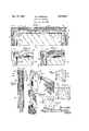
Fig. 1 is an elevational view of one face of a part of a storm sash embodying the invention;
Fig. 2 is an elevational view of the other side of one corner of the sash shown in Fig. 1;
Fig. 3 is a vertical sectional view taken substantially along the line 33 of Fig. 1;
Fig. 4 is a view similar to Fig. 1 and showing one atent 2,816,632 Patented Dec. 17, 1957 .2 corner -of .a. sash in whioh-the height. as well as the width has :been increased;
Fig. 5 is .an exploded'view-of the elementsutilized-under the present invention; and
Figsa .6, 7 .-and5.8 arewiews showing diiferent sash size variations that may beaccompli'shed.
For :purposes of disclosure the invention is herein illustrated as embodied inwa storm sash 10 that is partially shown in Fig. .1, .andfully'shownin Fig 7 of the drawings, anditwill be noted (that this sash has annpper rail 11, .abottomu-liail 12.andzia.;pair iofside rails 13 and and extension pieces E :wl1ich :serve-as, a frame for a panel such as a-pane of glass. .15...
Theside' rails .andatheextensions E .are .rnade from a metal such as alumiuumzwhich, in the present case, is extruded t0 th desired form, and :While the present invention may be applied =to=:r,ails,.made in different ways and of. difierent cross s'eetionaiforms, I have found that the present invention is;partic.ularly adaptable for use with extruded aluminum rail members ofthe cross sectional form shown -in:Eigs.- 3 and 5.5 This. particular cross sectionalform is illustrated .iurmy Prior Patent No. 2,666,598, and the mitered ends, orig-adjacent frame members are securedltogether bycorner bracket and attachment means disclosed in the aforesaid patent, certain modifications being made to enable the objectives of the present invention to be fully attained as will hereinafter be described. Reference is made to the, aforesaid prior patent for details of structure .andqoperation notspecifically .describedhere- ,in. Auxiliary sash of the aforesaid character may be readily and easily mounted on doublehung window frames .in the manner described in my co-pending applicationSerial No. 543,0 5, filed-October 27, 19.55.
Thus, asshow-n in detail in Figs. 3 and 5 of the drawings, the metal-extrusion from which the rails and .the
extensions .E areformed comprises an elongated body which in cross sectional form has a front wall 20 with twowal- ls 21 and 22 projecting therefrom to define what amounts to asecuring groove 23, and spaced inwardly from .the open side of this groove, a pair of ledges 24 and 25 extend toward each other so as to define a narrow slot 26.= The ledges 24 and 25 and the slot 26-serve to cooperate with the groove 23 to afford what may be termed an undercut fastening groove, while the space outwardly or to the left of the ledges 24 and 25 in Fig. 3 serves to afiord a clearance space within which portions of fastening elements maybe located in a protected portion as will be described. The wall member 21 constitutes -the outer edge of the frame or rail when a sash-is assembled, and inwardly of the wall 22, the metal of the extrusion is formed to receive the panel member that is to .be used in the sash. In the form herein illustrated the sash are to receive glass panes 15, and therefore parallel walls 27 and 28, are extended in spaced relation vand at right angles to the wall 22 to afford a glass mounting groove 30, the inner side wall surfaces of which are preferably serrated to exert a gripping action upon a resilent, U-shaped mounting strip ,31 made from rubber or a plastic. This mounting strip embraces the edge of the glass pane 15 and supports the pane in a cushioned relationship within the mounting groove 30.
The .ends of the frame elementsor tails are miter-ed, and are secured together by corner brackets 35 that are made from metal so as to have a relatively snug fit within will be afforded between the assembled elements.
the arms 35A so that binder head screws 38 may extend through the slot 26 and into the threaded openings 36. This positions the head of the screw 38 in the clearance space outwardly of the ledges 24 and 25, and by tightening the screws 38, the arms 35A of the corner brackets may be clamped firmly against the ledges 24 and 25, with the mitered ends of the rails in engaged relation. In this connection it is noted that when thus tightened, the inner end of the screw 38 is spaced from the wall 20.
In ordinary practice, the several rails that are to be used in making an auxiliary sash are cut to selected lengths that are determined by the dimensions of the window frame upon which the sash is to be used, and a highly advantageous way of merchandising the sash elements is to have the home owner measure the glass size of the sash upon which he wishes to provide a storm window or screen. Thus, for any particular window frame, the lengths of the rails for the auxiliary sash may be made in lengths that are mounted in the frame. It is found, however, that the relationship between the frame size and the glass pane size varies in different parts of the country. In the major markets of the country this variation in width and height of the frame for any particular glass pane size runs slightly more than /2 in each direction, and in order to distribute auxiliary sash kits throughout the country so as to meet the demands of the various major markets, provision must be made for assembling a particular kit in either one of two sizes, and in some instances of course additional sizes in the assembled sash will be required.
Under the present invention this is accomplished in a simple and economical manner through the use of the extension pieces E, which as will be evident in the drawings, are provided in right and left hand embodiments for cooperation with the right and left hand ends of the respective rails. In those instances where the frame dimensions are the minimum with respect to the particular glass size, the sash kit may be assembled in the manner illustrated in Fig. 6 of the drawings, or in other words,
without the use of the extension pieces E. If the extension pieces have a longitudinal dimension X, Figs. 2 and 4-, of A., then only one such extension piece B will be required in association with each of the rails to cover the range of variations that have thus far been encountered. However, an extension piece B may be provided at each end of a particular rail as shown in Fig. 1 to double the increase in length that is to be attained in the particular rail. Thus, as shown in Fig. 8, the frame may be made up with an extension piece at each end of the side rails,
or the frame may be made up with an extension piece at each end of two of the opposite or top and bottom rails. Finally, where the minimum extension is required, such an extension E may be placed at but one end of each of a pair of opposite rails. The arrangement provided by this invention thus affords a Wide range of adaptability of storm sash or screen sash kits.
The extensions E are provided with parallel mitered ends 40 so that an extension may be placed against the mitered end 41 of a rail such as the rail 11 in Fig. 2, and the other mitered edge 40 of the extension E will cooperate with the mitered edge 42 of the adjacent rail such as the rail 13 of Fig. 2. When the extension is put in this position, the related arm 35A extends through the undercut groove 23 of the extension E and extends for a substantial distance into the undercut groove of the aligned rail such as the rail 11 of Fig. 2. When thus related, the fastening screw 38 will be located in the aligned rail such as the rail 11, and when the fastening screws of the corner bracket 35 are tightened, the extension E will be held in accurately aligned relationship, and true mitered joints These corner structures that include the extensions B have been found to possess exceptional strength that is far beyond the strength necessary to provide a proper sash frame, and the miter joint that is afforded at each end of the 4 extension has been found to be unobjectionable from an artistic standpoint.
The extensions E, being relatively small, may be provided quite economically because they may be made from what would otherwise be scrap material, and since their production requires merely the making of mitered cuts that are the same as those employed on the main rails, these extensions may be readily produced with great accuracy and at a low cost.
From the foregoing description it will be apparent that the present invention enables sash kits to be produced and merchandised throughout all sections of the country despite variations that are encountered in different markets. Under the present invention the assembly of these kits may be performed without cutting or fitting operations, and the resulting storm sash or screen sash have the requisite strength and are neat in appearance. Through the present invention the stocking requirements for wholesale and retail distributors have been greatly reduced, and these objectives have been accomplished without appreciable increase in the cost in such sash kits.
Thus, while I have illustrated and described the invention in a particular embodiment, it will be recognized that changes and variations may be made within the spirit and scope of the invention.
I claim:
1. In a metal framed Window sash, a pair of side rails, top and bottom rails constituting a second pair of rails, all of said rails being of a predetermined cross sectional form having undercut longitudinal fastening grooves throughout their length and longitudinal mounting grooves throughout their length for mounting closure material in said frame, said rails having mitered ends, corner brackets extended into the respective fastening grooves, extension pieces of the same across section as said rails and having parallel mitered end edges, one of said pieces being disposed in aligned relation with at least one end of each of the rails of one of said pairs, said corner brackets having elements extended entirely through said pieces, and means securing said corner brackets to said rails to hold said pieces and said rails in assembled relation.
2. In a metal framed window sash, a pair of side rails, top and bottom rails constituting a second pair of rails, all of said rails being of a predetermined cross sectional form having longitudinal passages throughout their length and longitudinal mounting grooves throughout their length for mounting closure material in said frame, said rails having mitered ends, corner brackets extended into the respective passages, extension pieces of the same cross section as said rails having parallel mitered end edges, one of said pieces being disposed in aligned relation with at least one end of each of the rails of one of said pairs, said corner brackets having elements extended entirely through the passages in said pieces and into the passages of the aligned rails, and means securing said corner brackets to said rails to hold said pieces and said rails in assembled relation.
3. As an article of merchandise for assembly to produce a metal framed window sash for window frames of different dimensions, a pair of side rails, top and bottom rails constituting a second pair of rails, all of said rails being of a predetermined cross sectional form having undercut longitudinal fastening grooves throughout their length and longitudinal mounting grooves throughout their length for mounting closure material in said frame, said rails having mitered ends, extension pieces of the same cross section as said rails having parallel mitered end edges, corner brackets having arms of a length greater than the longitudinal dimension of said extension pieces and adapted to be extended into the respective fastening grooves, one of said pieces being adapted to be disposed in aligned relation with at least one end of each of the rails of one of said pairs with arms of the related said corner brackets extended entirely through said pieces, and
5 6 means on said arms of said brackets near the ends thereof 2,654,451 Schmidzall Oct. 6, 1953 for securing said corner brackets to said rails to hold said 2,666,508 Nardulli Ian. 19, 1954 pieces and said rails in assembled relation. FOREIGN PATENTS References Cited in the fil" of this patent 5 3 Great Britain P 23, 1921 UNITED STATES PATENTS 377,987 Boughton Feb. 14, 1888
Priority Applications (1)
| Application Number | Priority Date | Filing Date | Title |
|---|---|---|---|
| US553449A US2816632A (en) | 1955-12-16 | 1955-12-16 | Auxiliary windows |
Applications Claiming Priority (1)
| Application Number | Priority Date | Filing Date | Title |
|---|---|---|---|
| US553449A US2816632A (en) | 1955-12-16 | 1955-12-16 | Auxiliary windows |
Publications (1)
| Publication Number | Publication Date |
|---|---|
| US2816632A true US2816632A (en) | 1957-12-17 |
Family
ID=24209439
Family Applications (1)
| Application Number | Title | Priority Date | Filing Date |
|---|---|---|---|
| US553449A Expired - Lifetime US2816632A (en) | 1955-12-16 | 1955-12-16 | Auxiliary windows |
Country Status (1)
| Country | Link |
|---|---|
| US (1) | US2816632A (en) |
Cited By (27)
| Publication number | Priority date | Publication date | Assignee | Title |
|---|---|---|---|---|
| US2983001A (en) * | 1958-09-23 | 1961-05-09 | Clinton H Guldager | Window structure |
| US3131440A (en) * | 1961-07-14 | 1964-05-05 | Steelcraft Mfg Company | Extensible sectional sash assembly |
| US3177924A (en) * | 1960-08-29 | 1965-04-13 | Shelvey C Mcphail | Storm door assembly |
| US3186561A (en) * | 1963-12-04 | 1965-06-01 | Strassle Marcel | Profiled bar |
| US3230652A (en) * | 1963-05-01 | 1966-01-25 | Phelps Dodge Aluminum Products | Signboard |
| US3239978A (en) * | 1964-02-26 | 1966-03-15 | Parker John Herbert | Packaged door assembly |
| US3253847A (en) * | 1961-12-12 | 1966-05-31 | Reynolds Metals Co | Frame constructions and parts and methods for making the same or the like |
| US3255769A (en) * | 1964-01-23 | 1966-06-14 | Marshall O Lloyd | Protective housing |
| US3315414A (en) * | 1963-12-04 | 1967-04-25 | Reynolds Metals Co | Edgewise movable wall closure construction and method of making the same |
| US3417530A (en) * | 1966-11-21 | 1968-12-24 | Owens Corning Fiberglass Corp | Suspended ceiling system |
| US3534490A (en) * | 1968-07-09 | 1970-10-20 | Donald P Herbert | Section frame |
| US3634987A (en) * | 1969-06-23 | 1972-01-18 | Rafael R Huguet | Roll formed aluminum box frame construction and panel |
| US3922807A (en) * | 1974-01-31 | 1975-12-02 | Frank Shore | Multi-utility durable mitered picture frame |
| US4248022A (en) * | 1979-10-22 | 1981-02-03 | Weather Control Shutters, Inc. | Exterior window shutter assembly |
| FR2494573A1 (en) * | 1980-11-25 | 1982-05-28 | Portas Deutschland Gmbh | FRONT FURNITURE ELEMENT |
| US4899507A (en) * | 1987-02-27 | 1990-02-13 | Glaceries De Saint - Roch S.A. | Curved glazed panels |
| US5603192A (en) * | 1995-04-03 | 1997-02-18 | Advanced Equipment Corporation | Operable wall panel mounting apparatus |
| US20050073224A1 (en) * | 2003-09-03 | 2005-04-07 | Livingston Steven J. | Modular cabinet system |
| US20060268403A1 (en) * | 2003-08-26 | 2006-11-30 | Cadio Michael A | Extrusions and corner brackets for a screen frame of a rear projection display |
| US20070125016A1 (en) * | 2005-11-18 | 2007-06-07 | Shawn Yu | Wall panel with corner-connected open frame |
| US20100090089A1 (en) * | 2007-01-31 | 2010-04-15 | Martin Koegel | Device and method for producing shuttering elements |
| US7818927B1 (en) * | 2003-08-07 | 2010-10-26 | John Gary K | Removable window insulator |
| US20130205706A1 (en) * | 2011-11-03 | 2013-08-15 | Proformance Manufacturing, Inc. | Frame assembly having a corner key |
| US20150300027A1 (en) * | 2012-11-06 | 2015-10-22 | Simon Day | Cladding assembly |
| EP3623562A1 (en) * | 2018-09-11 | 2020-03-18 | Garner Aluminium Extrusions Limited | Frame assembly |
| EP3922804A1 (en) * | 2020-04-09 | 2021-12-15 | Westermann KG | Furniture part |
| US11473320B2 (en) * | 2016-07-06 | 2022-10-18 | Peri Se | Compensating ceiling formwork element for building around an obstacle |
Citations (4)
| Publication number | Priority date | Publication date | Assignee | Title |
|---|---|---|---|---|
| US377987A (en) * | 1888-02-14 | Insect-screen | ||
| GB185033A (en) * | 1921-09-23 | 1922-08-31 | John Thoburn Mcgaw | Improvements in or relating to extensible picture frames or the like |
| US2654451A (en) * | 1950-11-13 | 1953-10-06 | John R Schmidgall | Frame construction |
| US2666508A (en) * | 1949-08-10 | 1954-01-19 | Michael J Nardulli | Window sash frame structure |
-
1955
- 1955-12-16 US US553449A patent/US2816632A/en not_active Expired - Lifetime
Patent Citations (4)
| Publication number | Priority date | Publication date | Assignee | Title |
|---|---|---|---|---|
| US377987A (en) * | 1888-02-14 | Insect-screen | ||
| GB185033A (en) * | 1921-09-23 | 1922-08-31 | John Thoburn Mcgaw | Improvements in or relating to extensible picture frames or the like |
| US2666508A (en) * | 1949-08-10 | 1954-01-19 | Michael J Nardulli | Window sash frame structure |
| US2654451A (en) * | 1950-11-13 | 1953-10-06 | John R Schmidgall | Frame construction |
Cited By (35)
| Publication number | Priority date | Publication date | Assignee | Title |
|---|---|---|---|---|
| US2983001A (en) * | 1958-09-23 | 1961-05-09 | Clinton H Guldager | Window structure |
| US3177924A (en) * | 1960-08-29 | 1965-04-13 | Shelvey C Mcphail | Storm door assembly |
| US3131440A (en) * | 1961-07-14 | 1964-05-05 | Steelcraft Mfg Company | Extensible sectional sash assembly |
| US3253847A (en) * | 1961-12-12 | 1966-05-31 | Reynolds Metals Co | Frame constructions and parts and methods for making the same or the like |
| US3230652A (en) * | 1963-05-01 | 1966-01-25 | Phelps Dodge Aluminum Products | Signboard |
| US3186561A (en) * | 1963-12-04 | 1965-06-01 | Strassle Marcel | Profiled bar |
| US3315414A (en) * | 1963-12-04 | 1967-04-25 | Reynolds Metals Co | Edgewise movable wall closure construction and method of making the same |
| US3255769A (en) * | 1964-01-23 | 1966-06-14 | Marshall O Lloyd | Protective housing |
| US3239978A (en) * | 1964-02-26 | 1966-03-15 | Parker John Herbert | Packaged door assembly |
| US3417530A (en) * | 1966-11-21 | 1968-12-24 | Owens Corning Fiberglass Corp | Suspended ceiling system |
| US3534490A (en) * | 1968-07-09 | 1970-10-20 | Donald P Herbert | Section frame |
| US3634987A (en) * | 1969-06-23 | 1972-01-18 | Rafael R Huguet | Roll formed aluminum box frame construction and panel |
| US3922807A (en) * | 1974-01-31 | 1975-12-02 | Frank Shore | Multi-utility durable mitered picture frame |
| US4248022A (en) * | 1979-10-22 | 1981-02-03 | Weather Control Shutters, Inc. | Exterior window shutter assembly |
| US4783945A (en) * | 1980-11-25 | 1988-11-15 | Portas Deutschland Gmbh | Furniture front element |
| FR2494573A1 (en) * | 1980-11-25 | 1982-05-28 | Portas Deutschland Gmbh | FRONT FURNITURE ELEMENT |
| US4707204A (en) * | 1980-11-25 | 1987-11-17 | Portas Deutschland Gmbh | Method of making a furniture front element |
| US4899507A (en) * | 1987-02-27 | 1990-02-13 | Glaceries De Saint - Roch S.A. | Curved glazed panels |
| US5603192A (en) * | 1995-04-03 | 1997-02-18 | Advanced Equipment Corporation | Operable wall panel mounting apparatus |
| US7818927B1 (en) * | 2003-08-07 | 2010-10-26 | John Gary K | Removable window insulator |
| US20060268403A1 (en) * | 2003-08-26 | 2006-11-30 | Cadio Michael A | Extrusions and corner brackets for a screen frame of a rear projection display |
| US20050073224A1 (en) * | 2003-09-03 | 2005-04-07 | Livingston Steven J. | Modular cabinet system |
| WO2005023590A3 (en) * | 2003-09-03 | 2006-08-24 | I D Furniture Systems Inc | Modular cabinet system |
| US7207636B2 (en) * | 2003-09-03 | 2007-04-24 | I.D. Furniture Systems, Inc. | Modular cabinet system |
| US20080042531A1 (en) * | 2003-09-03 | 2008-02-21 | Livingston Steven J | Modular cabinet system |
| US20070125016A1 (en) * | 2005-11-18 | 2007-06-07 | Shawn Yu | Wall panel with corner-connected open frame |
| US20100090089A1 (en) * | 2007-01-31 | 2010-04-15 | Martin Koegel | Device and method for producing shuttering elements |
| US8663779B2 (en) * | 2007-01-31 | 2014-03-04 | Martin Koegl | Formwork panel with frame containing an electronic identification element |
| US20130205706A1 (en) * | 2011-11-03 | 2013-08-15 | Proformance Manufacturing, Inc. | Frame assembly having a corner key |
| US8857129B2 (en) * | 2011-11-03 | 2014-10-14 | Proformance Maufacturing, Inc. | Frame assembly having a corner key |
| US20150300027A1 (en) * | 2012-11-06 | 2015-10-22 | Simon Day | Cladding assembly |
| US9487956B2 (en) * | 2012-11-06 | 2016-11-08 | Simon Day | Cladding assembly |
| US11473320B2 (en) * | 2016-07-06 | 2022-10-18 | Peri Se | Compensating ceiling formwork element for building around an obstacle |
| EP3623562A1 (en) * | 2018-09-11 | 2020-03-18 | Garner Aluminium Extrusions Limited | Frame assembly |
| EP3922804A1 (en) * | 2020-04-09 | 2021-12-15 | Westermann KG | Furniture part |
Similar Documents
| Publication | Publication Date | Title |
|---|---|---|
| US2816632A (en) | Auxiliary windows | |
| US3975875A (en) | Decorative exterior trim system for windows | |
| US3340661A (en) | Ornamental grill | |
| US3861444A (en) | Extruded plastic window frame | |
| US3696857A (en) | Panel and frame assembly | |
| US2292273A (en) | Window assembly | |
| US3641721A (en) | Maintenance-free door light insert assembly | |
| US2226254A (en) | Double glazed window | |
| US2667245A (en) | Storm sash construction | |
| GB1203331A (en) | Channel member for sashless window with meeting rail | |
| US2559764A (en) | Window frame and sash | |
| US3024503A (en) | Storm sash | |
| US2780846A (en) | Removable secondary glazing for windows | |
| DE59408775D1 (en) | WINDOW WING FRAME HOLLOW PROFILE AND EXISTING DOUBLE WING WINDOW FRAME | |
| US2063120A (en) | Store front construction | |
| DE29521122U1 (en) | Wood-aluminum windows | |
| US4413397A (en) | Metal door and light assembly | |
| US2866237A (en) | Weatherstrip mounting assembly | |
| US1700502A (en) | Sash construction | |
| US2800957A (en) | Adjustable screen window and door frame | |
| US1735048A (en) | Weather-strip support | |
| US1890615A (en) | Store front construction | |
| US2279171A (en) | Door or window frame construction | |
| EP0201384A3 (en) | Protecting profile for a window pane glued on a body panel of a vehicle | |
| GB2110284A (en) | Frame member for doors and windows |