US2815744A - Surface grinder equipped with motorized crush roller - Google Patents
Surface grinder equipped with motorized crush roller Download PDFInfo
- Publication number
- US2815744A US2815744A US504296A US50429655A US2815744A US 2815744 A US2815744 A US 2815744A US 504296 A US504296 A US 504296A US 50429655 A US50429655 A US 50429655A US 2815744 A US2815744 A US 2815744A
- Authority
- US
- United States
- Prior art keywords
- spindle
- crush
- crush roller
- roller
- grinding wheel
- Prior art date
- Legal status (The legal status is an assumption and is not a legal conclusion. Google has not performed a legal analysis and makes no representation as to the accuracy of the status listed.)
- Expired - Lifetime
Links
Images


Classifications
-
- B—PERFORMING OPERATIONS; TRANSPORTING
- B24—GRINDING; POLISHING
- B24B—MACHINES, DEVICES, OR PROCESSES FOR GRINDING OR POLISHING; DRESSING OR CONDITIONING OF ABRADING SURFACES; FEEDING OF GRINDING, POLISHING, OR LAPPING AGENTS
- B24B53/00—Devices or means for dressing or conditioning abrasive surfaces
- B24B53/06—Devices or means for dressing or conditioning abrasive surfaces of profiled abrasive wheels
- B24B53/07—Devices or means for dressing or conditioning abrasive surfaces of profiled abrasive wheels by means of forming tools having a shape complementary to that to be produced, e.g. blocks, profile rolls
-
- Y—GENERAL TAGGING OF NEW TECHNOLOGICAL DEVELOPMENTS; GENERAL TAGGING OF CROSS-SECTIONAL TECHNOLOGIES SPANNING OVER SEVERAL SECTIONS OF THE IPC; TECHNICAL SUBJECTS COVERED BY FORMER USPC CROSS-REFERENCE ART COLLECTIONS [XRACs] AND DIGESTS
- Y10—TECHNICAL SUBJECTS COVERED BY FORMER USPC
- Y10T—TECHNICAL SUBJECTS COVERED BY FORMER US CLASSIFICATION
- Y10T74/00—Machine element or mechanism
- Y10T74/19—Gearing
- Y10T74/19614—Disconnecting means
Definitions
- This invention relates to surface grinding machines and refers more particularly to surface grinders in which the grinding wheel is dressed by crush forming.
- Crush form grinding once used mainly in the production of thread forms on cylindrical grinders, has been rapidly adapted to surface grinders for the production of linear forms, to permit the grinding of irregular profiles on solid, hardened stock.
- the grinding wheel is dressed to the desired form by rolling it slowly under pressure against a steel roller having a profile identical to that which is to be produced in the work and whereby the peripheral wheel face is crushed away until it assumes a form complementary to that of the steel crush roller.
- the wheel is dressed in this manner whenever it begins to depart from the tolerance limits of the desired profile.
- the abrasive material of the grinding wheel acting upon the crush roller, causes the crush roller to lose form after a number of dressings, and the crush roller must then be turned in some manner.
- One conventional method of truing the crush roller is to grind it in cylindrical grinding fashion with a grinding wheel which has first been dressed by means of a master crush roller.
- the grinding wheel used for this truing of the crush roller is the same grinding wheel used for production and which is normally dressed by the production crush roller, since the production grinding wheel conforms fairly well to the profile of the master crush roller and therefore imposes little wear on the master crush roller, assuring long life for the latter.
- Another object of this invention resides in the provision of a surface grinder of the crush form type wherein the crush roller is mounted on an end portion of a spindle, with no outboard bearing to interfere with ready removability of the crush roller, to thus greatly facilitate replacement of crush rollers and to thus permit reforming of the crush roller on the same machine used for production of work.
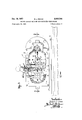
- Figure 1 is a front elevational view of a surface grinder embodying the principles of this invention
- FIG 2 is a perspective view of the motorized crush roller of the grinder shown in Figure 1;
- FIG 3 is a rear elevational view of the motorized crush roller shown in Figure 2, with portions broken away;
- Figure 4 is a vertical sectional view taken on the plane of the line 44 in Figure 3;
- Figure 5 is a horizontal sectional view taken on the plane of the line 5-5 in Figure 3;
- Figure 6 is a fragmentary disassembled perspective view of the crush roller and its spindle, portions being shown in section.
- the numeral 5 designates generally a surface grinder comprising a fixed base 6 having a table 7 reciprocably mounted thereon by means of which pieces of work, secured on the upper surface of the table, may be carried beneath an abrasive grinding wheel 8 which shapes and finishes the upper surface of the work to a profile corresponding to that on the peripheral surface 9 of the grinding wheel.
- the profile of the grinding surface of the wheel corresponds to that of the periphery of a crush roller 10 by means of which the wheel may be periodically dressed.
- the crush roller together with an electric motor 11 by which it may be powered and a transmission designated generally by 12 and by which the crush roller may be drivingly connected with the motor, is mounted on a bracket designated generally by 13 secured to one end of the table. rection to a position beyond the normal limit of its work carrying travel, with the crush roller directly below the grinding wheel, the grinding wheel may engage the crush roller under pressure to be dressed thereby.
- the bracket 13 which supports the crush roller 1%) i its drive motor 11 has a base 17 which carries a bearing support 13 and a transmission housing 19 at one end of which the motor 11 is mounted.
- the bearing support portion 18 of the bracket projects upwardly from the rear of the base portion and has a bore 24 therethrough and a pair of oppositely opening counterbores .25.
- the axis of the bore and counterbores Patented Dec. 10, 1957 When the table is moved in one di- 3 extends transversely to the path of reciprocation of the table and parallel-to the 'axi's'of the grinding wheel.
- Combined radial and thrust bearings 26 and 26' are snugly seated in the counterbores, and in these bearings is journaled a spindle 27 upon which the crush roller 10 is readily removably mounted in a manner described hereinafter.
- the crush roller is mounted on a portion of the spindle which projects forwardly beyond the frontbe'a'r'ing 26, in line with the grinding wheel, and to the rear end portion of the spindle, which extends beyond the rear bearing 26, a driven gear 28, comprising part of the transmission 12, is nonrotatably secured.
- the spindle has front and rear shoulders which oppose and cooperate with the shoulders 29, 29 on the bearing support; the front shoulder comprises an integral enlarged diameter portion 30 on the spindle, while the rear shoulder is provided by a collar 31 threaded onto the spindle.
- the driven gear 28 may be removably secured to the spindle, as by means of a split ring 33 or the like, to permit the spindle to be withdrawn from the bearings, and it is of course keyed to the spindle or otherwise constrained to rotate therewith.
- the crush roller When the grinding wheel is to be dressed by means of the crush roller, the crush roller should be freely rotatable, rotation being imparted thereto by the grinding wheel which is at that time driven at low speed; but when the production crush roller must be trued by means of the grinding wheel (to which an accurate profile has been imparted by means of a master crush roller), it is necessary that the crush roller be positively driven in the same manner as any other work piece being ground in cylindrical grinding fashion.
- the transmission now about to be described permits the spindle either to idle, to enable normal crush dressing of the grinding wheel, or to be rotatably driven to enable truing of a crush roller from the grinding wheel after the latter has been accurately crush dressed from a master crush roller.
- the transmission (see Figures 3 and comprises, in general, a drive pinion 35 on the shaft of the motor 11, an idler gear 36 which is at all times drivingly meshed with the drive pinion, an idler pinion 37 coaxial with the idler gear and constrained to rotate therewith, and a transmission gear 38 mounted for bodily shifting to and from meshing engagement with the idler pinion 37 and the driven gear 28 on the spindle.
- the transmission housing 19, which encloses the transmission includes spaced apart front and rear walls 39, 39' which provide bearings journaling the shaft 40 which is common to the idler gear 36 and idler pinion 37.
- the front Wall 39 of the trans mission housing also provides the mounting for the crush roller drive motor 11.
- An arm 42 swingably mounted on the rear end portion of the idler gear shaft 40, carries a forwardly extending stub shaft 43 upon which the transmission gear 38 is mounted.
- the transmission gear is at all times in meshing engagement with the idler pinion because the swingable arm 42 pivots about the rotational axis of the idler pinion, thus holding the transmission gear axis at all times spaced the same distance from the idler pinion axis, but as the arm swings up and down it carries the transmission gear into and out of meshing engagement with the driven gear 28 on the spindle.
- the arm may be actuated for such swinging motion by means of an upright endwise reciprocable rod 44 having its lower end portion confined between bifurcations 45 at the free end portion of the swingable arm and connected with the'arm by means of a'transverse pin 46 at the lower end of the rod engaged in a lengthwise extending slot 47 in the free end portion'of the arm;
- a knob 48 at'the'top ofthe' rodfacilitatesitsactuation to a'raise'd osition; in"
- a rotatable collar 50 having an eccentric substantially keyhole-shaped bore therein, and when the shaft is in its raised position this collar may be manually rotated to bring the narrower portion of its bore around to alignement with the rod, whereby the collar engages in a circumferential groove 52 in the rod to prevent the rod from dropping.
- the raised position of the shaft, in which the transmission is engaged may be accurately defined by means of a downwardly projecting stop screw 53 engageable by the arm 42 and adjustable to prevent the arm from being swung upwardly beyond the position in which the transmission gear is accurately meshed with the driven gear.
- the single spindle serves to mount both a master crush roll and a production crush roll, in turn, and such employment of the spindle is further facilitated by the fact that the crush rollers may be readily removed or replaced on the spindle by reason of there being no hearing at the front of the spindle to get in the way of the crush roller as it is axially withdrawn from or slipped onto the spindle. Removability of the crush roller is further facilitated by reason of its securement to the spindle by means of a nut 54, engageable on a threaded front end portion 55 of the spindle to confine the crush roller against a forwardly facing shoulder 56 provided by the integral enlarged diameter portion 30 on the spindle.
- the bearing support portion of the bracket directly behind the crush roller, carries an annular seal ring 58 which has circumferential engagement with the enlarged diameter portion 30 of the spindle.
- this invention provides a surface grinder for crush grinding wherein the production crush roller is readily removable, for replacement by a master crush roller, by reason of the fact that the crush roller is mounted on the projecting end portion of its spindle where no outboard bearing interferes with its axial withdrawal from the spindle, and that in the surface grinder of this invention the spindle may either be permitted to idle, for normal crush dressing" of the" grinding wheel, or may be rotatably driven to enable truing of a production crush roller in cylindrical grinding fashion, selection of the desired type of operation being readily accomplished by means of a simple and efficient transmission.
- a unitary crush form grinding attachment for a surface grinder of the type wherein work is carried toward and from engagement with a grinding wheel as a consequence of reciprocatory motion of a work table upon which the work is secured said attachment comprising: an upright bearing support; a spindle journaled in said bearing support for rotation on a horizontal axis and having front and rear end portions projecting from the bearing support; a substantially horizontal base joined to and having a portion extending forwardly from the lower portion of the bearing support, under the projecting front end portion of the spindle, to provide for securement of the support to a reciprocable work table with the spindle axis disposed crosswise of the path along which the table travels; a roller detachably secured to the projecting front end portion of the spindle with the roller disposed over said forwardly extending portion of the base; an upright motor supporting wall secured to the rear of the bearing support and having an aperture therein through which the rear end portion of the spindle projects, said wall having a portion extending laterally a distance to one side of
- the unitary crush form grinding attachment set forth in claim 1 further characterized by: the fact that said gearing includes a transmission gear carried by the transmission housing, at all times drivingly connected with the gear on the motor shaft, and meshing with the spindle carried gear to transmit rotation from the motor to the spindle; the provision of means on the housing mounting said transmission gear for motion in opposite directions along a path normal to the spindle axis to enable the transmission gear to be moved into and out of meshing engagement with the spindle carried gear; and by the pro vision of a manually operable gear shift device connected with said transmission gear and having a handle thereon accessible at the exterior of the upper portion of the transmission housing, by which the transmission gear may be shifted into and out of mesh with the spindle carried gear.
Description
Dec. 10, .1957
R. L. CRANE SURFACE GRINDEREQUIPPED WITH MQTdRiZED CRUSH ROLLER 5 Sheets-Sheet 1 Filed April 27, 1955 R; L.-CRANE SURFACE GRINDER EQUIPPED WITH MOTORIZED CRUSH ROLLER Filed April 27, 1955 Dec. 10, 1957 5 Sheets-Shet 2 R. 1., CRANE Dec. 10, 195
SURFACE GRINDER EQUIPPED WI' IH MOTORIZED CRUSH ROLLER 5 Sheets-Sheet 3 Filed April 27. 1955 Dec. 10, 1957 R L. CRANE 2,815,744
SURFACE GRINDER EQUIPPED WITH MOTORIZED CRUSH ROLLER Filed April 27, 1955 5 Sheets-Sheet 4 Dec. 10, 1957 R. L. CRANE 2,815,744
SURFACE GRINDER EQUIPPED wrm yoToRIzEn CRUSH ROLLER Filed April 27, 1955 s sneaks-sheet 5 SURFACE GRINDER EQUIPPED H MOTORIZED CRUSH ROLLER Robert L. Crane, Hopkins, Minn, assignor to Continental Machines, lnc., Savage, Minn., a corporation of Mmnesota Application April 27, 1955, Serial No. 504,296
2 Claims. (Cl. 125-11) This invention relates to surface grinding machines and refers more particularly to surface grinders in which the grinding wheel is dressed by crush forming.
Crush form grinding, once used mainly in the production of thread forms on cylindrical grinders, has been rapidly adapted to surface grinders for the production of linear forms, to permit the grinding of irregular profiles on solid, hardened stock. In this technique the grinding wheel is dressed to the desired form by rolling it slowly under pressure against a steel roller having a profile identical to that which is to be produced in the work and whereby the peripheral wheel face is crushed away until it assumes a form complementary to that of the steel crush roller.
The wheel is dressed in this manner whenever it begins to depart from the tolerance limits of the desired profile. Obviously, however, the abrasive material of the grinding wheel, acting upon the crush roller, causes the crush roller to lose form after a number of dressings, and the crush roller must then be turned in some manner. One conventional method of truing the crush roller is to grind it in cylindrical grinding fashion with a grinding wheel which has first been dressed by means of a master crush roller. Desirably the grinding wheel used for this truing of the crush roller is the same grinding wheel used for production and which is normally dressed by the production crush roller, since the production grinding wheel conforms fairly well to the profile of the master crush roller and therefore imposes little wear on the master crush roller, assuring long life for the latter.
It is an object of the present invention to provide a surface grinder of the crush form type wherein the production crush roller by which the grinding wheel is normally dressed may be very readily and quickly removed from its spindle to permit its replacement by a master crush roller, so that the grinding wheel may be accurately dressed by the master crush roller and used in cylindrical grinding fashion to true the production crush roller when the latter is replaced on the spindle.
Another object of this invention resides in the provision of a surface grinder of the crush form type wherein the crush roller is mounted on an end portion of a spindle, with no outboard bearing to interfere with ready removability of the crush roller, to thus greatly facilitate replacement of crush rollers and to thus permit reforming of the crush roller on the same machine used for production of work.
A further object of this invention resides in the provision atent O With the above and other objects in view, which will appear as the description proceeds, this invention resides in the novel construction, combination and arrangement of parts substantially as hereinafter described and more particularly defined by the appended claims, it being understood that such changes in the precise embodiment of the hereindisclosed invention may be made as come within the scope of the claims.
The accompanying drawings illustrate one complete example of the physical embodiment of the invention constructed according to the best mode so far devised for the practical application of the principles thereof and in which:
Figure 1 is a front elevational view of a surface grinder embodying the principles of this invention;
Figure 2 is a perspective view of the motorized crush roller of the grinder shown in Figure 1;
Figure 3 is a rear elevational view of the motorized crush roller shown in Figure 2, with portions broken away;
Figure 4 is a vertical sectional view taken on the plane of the line 44 in Figure 3;
Figure 5 is a horizontal sectional view taken on the plane of the line 5-5 in Figure 3; and
Figure 6 is a fragmentary disassembled perspective view of the crush roller and its spindle, portions being shown in section.
Referring now to the accompanying drawings, the numeral 5 designates generally a surface grinder comprising a fixed base 6 having a table 7 reciprocably mounted thereon by means of which pieces of work, secured on the upper surface of the table, may be carried beneath an abrasive grinding wheel 8 which shapes and finishes the upper surface of the work to a profile corresponding to that on the peripheral surface 9 of the grinding wheel.
The profile of the grinding surface of the wheel, in turn, corresponds to that of the periphery of a crush roller 10 by means of which the wheel may be periodically dressed. The crush roller, together with an electric motor 11 by which it may be powered and a transmission designated generally by 12 and by which the crush roller may be drivingly connected with the motor, is mounted on a bracket designated generally by 13 secured to one end of the table. rection to a position beyond the normal limit of its work carrying travel, with the crush roller directly below the grinding wheel, the grinding wheel may engage the crush roller under pressure to be dressed thereby.
It will be understood by those skilled in the art that the grinding wheel may be raised and lowered by means The bracket 13 which supports the crush roller 1%) i its drive motor 11 has a base 17 which carries a bearing support 13 and a transmission housing 19 at one end of which the motor 11 is mounted. Lengthwise extending slots 20 in the top of the table, having an inverted T-shaped cross section, accommodate correspondingly shaped heads 21 of bolts which are secured in the bracket base to thus hold the bracket in any of a number of positions along the length of the table. 1
The bearing support portion 18 of the bracket projects upwardly from the rear of the base portion and has a bore 24 therethrough and a pair of oppositely opening counterbores .25. The axis of the bore and counterbores Patented Dec. 10, 1957 When the table is moved in one di- 3 extends transversely to the path of reciprocation of the table and parallel-to the 'axi's'of the grinding wheel. Combined radial and thrust bearings 26 and 26' are snugly seated in the counterbores, and in these bearings is journaled a spindle 27 upon which the crush roller 10 is readily removably mounted in a manner described hereinafter. The crush roller is mounted on a portion of the spindle which projects forwardly beyond the frontbe'a'r'ing 26, in line with the grinding wheel, and to the rear end portion of the spindle, which extends beyond the rear bearing 26, a driven gear 28, comprising part of the transmission 12, is nonrotatably secured.
Opposing shoulders 29, 29' defined by the junctions of the front and rear counterbores 25 with the bore 24 through the bearing support engage the bearings 26 and 26', respectively, topreclu'de end play of the spindle and thus assure that the crush roller will at all times align with the grinding wheel. The spindle has front and rear shoulders which oppose and cooperate with the shoulders 29, 29 on the bearing support; the front shoulder comprises an integral enlarged diameter portion 30 on the spindle, while the rear shoulder is provided by a collar 31 threaded onto the spindle. The driven gear 28 may be removably secured to the spindle, as by means of a split ring 33 or the like, to permit the spindle to be withdrawn from the bearings, and it is of course keyed to the spindle or otherwise constrained to rotate therewith.
When the grinding wheel is to be dressed by means of the crush roller, the crush roller should be freely rotatable, rotation being imparted thereto by the grinding wheel which is at that time driven at low speed; but when the production crush roller must be trued by means of the grinding wheel (to which an accurate profile has been imparted by means of a master crush roller), it is necessary that the crush roller be positively driven in the same manner as any other work piece being ground in cylindrical grinding fashion. The transmission now about to be described permits the spindle either to idle, to enable normal crush dressing of the grinding wheel, or to be rotatably driven to enable truing of a crush roller from the grinding wheel after the latter has been accurately crush dressed from a master crush roller.
The transmission (see Figures 3 and comprises, in general, a drive pinion 35 on the shaft of the motor 11, an idler gear 36 which is at all times drivingly meshed with the drive pinion, an idler pinion 37 coaxial with the idler gear and constrained to rotate therewith, and a transmission gear 38 mounted for bodily shifting to and from meshing engagement with the idler pinion 37 and the driven gear 28 on the spindle. The transmission housing 19, which encloses the transmission, includes spaced apart front and rear walls 39, 39' which provide bearings journaling the shaft 40 which is common to the idler gear 36 and idler pinion 37. The front Wall 39 of the trans mission housing also provides the mounting for the crush roller drive motor 11.
An arm 42, swingably mounted on the rear end portion of the idler gear shaft 40, carries a forwardly extending stub shaft 43 upon which the transmission gear 38 is mounted. The transmission gear is at all times in meshing engagement with the idler pinion because the swingable arm 42 pivots about the rotational axis of the idler pinion, thus holding the transmission gear axis at all times spaced the same distance from the idler pinion axis, but as the arm swings up and down it carries the transmission gear into and out of meshing engagement with the driven gear 28 on the spindle.
The arm may be actuated for such swinging motion by means of an upright endwise reciprocable rod 44 having its lower end portion confined between bifurcations 45 at the free end portion of the swingable arm and connected with the'arm by means of a'transverse pin 46 at the lower end of the rod engaged in a lengthwise extending slot 47 in the free end portion'of the arm; A knob 48 at'the'top ofthe' rodfacilitatesitsactuation to a'raise'd osition; in"
which the arm is lifted to engage the transmission gear with the driven gear on the spindle, or to a lowered position in which the spindle and the crush roller mounted thereon may be freely rotated by the grinding wheel to crush dress the same. At the top of the transmission housing, surrounding the rod is a rotatable collar 50 having an eccentric substantially keyhole-shaped bore therein, and when the shaft is in its raised position this collar may be manually rotated to bring the narrower portion of its bore around to alignement with the rod, whereby the collar engages in a circumferential groove 52 in the rod to prevent the rod from dropping. The raised position of the shaft, in which the transmission is engaged, may be accurately defined by means of a downwardly projecting stop screw 53 engageable by the arm 42 and adjustable to prevent the arm from being swung upwardly beyond the position in which the transmission gear is accurately meshed with the driven gear.
Because of the ease with which the transmission may be engaged and disengaged, the single spindle serves to mount both a master crush roll and a production crush roll, in turn, and such employment of the spindle is further facilitated by the fact that the crush rollers may be readily removed or replaced on the spindle by reason of there being no hearing at the front of the spindle to get in the way of the crush roller as it is axially withdrawn from or slipped onto the spindle. Removability of the crush roller is further facilitated by reason of its securement to the spindle by means of a nut 54, engageable on a threaded front end portion 55 of the spindle to confine the crush roller against a forwardly facing shoulder 56 provided by the integral enlarged diameter portion 30 on the spindle.
To prevent abrasive particles and other foreign matter from entering the bearings, the bearing support portion of the bracket, directly behind the crush roller, carries an annular seal ring 58 which has circumferential engagement with the enlarged diameter portion 30 of the spindle.
From the foregoing description, taken together with the accompanying drawings, it will be readily apparent that this invention provides a surface grinder for crush grinding wherein the production crush roller is readily removable, for replacement by a master crush roller, by reason of the fact that the crush roller is mounted on the projecting end portion of its spindle where no outboard bearing interferes with its axial withdrawal from the spindle, and that in the surface grinder of this invention the spindle may either be permitted to idle, for normal crush dressing" of the" grinding wheel, or may be rotatably driven to enable truing of a production crush roller in cylindrical grinding fashion, selection of the desired type of operation being readily accomplished by means of a simple and efficient transmission.
What I claim as my invention is:
1. A unitary crush form grinding attachment for a surface grinder of the type wherein work is carried toward and from engagement with a grinding wheel as a consequence of reciprocatory motion of a work table upon which the work is secured, said attachment comprising: an upright bearing support; a spindle journaled in said bearing support for rotation on a horizontal axis and having front and rear end portions projecting from the bearing support; a substantially horizontal base joined to and having a portion extending forwardly from the lower portion of the bearing support, under the projecting front end portion of the spindle, to provide for securement of the support to a reciprocable work table with the spindle axis disposed crosswise of the path along which the table travels; a roller detachably secured to the projecting front end portion of the spindle with the roller disposed over said forwardly extending portion of the base; an upright motor supporting wall secured to the rear of the bearing support and having an aperture therein through which the rear end portion of the spindle projects, said wall having a portion extending laterally a distance to one side of the bearing support and said laterally extending wall portion having a hole therein; a gear on the rear end portion of the spindle, rearwardly of said wall; an electric motor mounted on said laterally extending wall portion in sideby-side relation to the bearing support, with its shaft parallel to the spindle and projecting rearwardly through said hole; a gear on said projecting portion of the motor shaft, rearwardly of said wall portion and substantially laterally opposite the spindle carried gear; means secured to and cooperating with said upright wall providing a transmission housing rearwardly of the motor and the bearing support and which housing is substantially shallow in that dimension which is measured along a line parallel to the spindle axis; and gearing in said housing for drivingly connecting the motor shaft gear with the spindle carried gear.
2. The unitary crush form grinding attachment set forth in claim 1 further characterized by: the fact that said gearing includes a transmission gear carried by the transmission housing, at all times drivingly connected with the gear on the motor shaft, and meshing with the spindle carried gear to transmit rotation from the motor to the spindle; the provision of means on the housing mounting said transmission gear for motion in opposite directions along a path normal to the spindle axis to enable the transmission gear to be moved into and out of meshing engagement with the spindle carried gear; and by the pro vision of a manually operable gear shift device connected with said transmission gear and having a handle thereon accessible at the exterior of the upper portion of the transmission housing, by which the transmission gear may be shifted into and out of mesh with the spindle carried gear.
References Cited in the file of this patent UNITED STATES PATENTS 1,262,666 Heinze Apr. 16, 1918 1,535,452 Conradson Apr. 28, 1925 1,828,369 Hodges Oct. 20, 1931 2,021,220 Ballard Nov. 19, 1935 2,395,139 Nord Feb. 19, 1946 2,560,654 Lohutko July 17, 1951 2,585,990 Baldenhofer Feb. 19, 1952 2,590,102 Hopkins Mar. 25, 1952 2,720,062 Fouquet Oct. 11, 1953
Priority Applications (1)
| Application Number | Priority Date | Filing Date | Title |
|---|---|---|---|
| US504296A US2815744A (en) | 1955-04-27 | 1955-04-27 | Surface grinder equipped with motorized crush roller |
Applications Claiming Priority (1)
| Application Number | Priority Date | Filing Date | Title |
|---|---|---|---|
| US504296A US2815744A (en) | 1955-04-27 | 1955-04-27 | Surface grinder equipped with motorized crush roller |
Publications (1)
| Publication Number | Publication Date |
|---|---|
| US2815744A true US2815744A (en) | 1957-12-10 |
Family
ID=24005660
Family Applications (1)
| Application Number | Title | Priority Date | Filing Date |
|---|---|---|---|
| US504296A Expired - Lifetime US2815744A (en) | 1955-04-27 | 1955-04-27 | Surface grinder equipped with motorized crush roller |
Country Status (1)
| Country | Link |
|---|---|
| US (1) | US2815744A (en) |
Cited By (2)
| Publication number | Priority date | Publication date | Assignee | Title |
|---|---|---|---|---|
| US3212491A (en) * | 1961-08-21 | 1965-10-19 | Cavitron Corp | Method and apparatus for trueing and forming the working surface of a grinding wheel |
| US3662732A (en) * | 1970-04-30 | 1972-05-16 | Brown & Sharpe Mfg | Grinding wheel dresser |
Citations (9)
| Publication number | Priority date | Publication date | Assignee | Title |
|---|---|---|---|---|
| US1262666A (en) * | 1916-03-01 | 1918-04-16 | John O Heinze Company | Starting device for internal-combustion engines. |
| US1535452A (en) * | 1923-02-15 | 1925-04-28 | Giddings & Lewis | Grinding machine |
| US1828369A (en) * | 1928-10-24 | 1931-10-20 | Vera C Hodges | Engine starter |
| US2021220A (en) * | 1931-06-29 | 1935-11-19 | United Shoe Machinery Corp | Driving mechanism |
| US2395139A (en) * | 1943-06-04 | 1946-02-19 | U S Automatic Corp | Adapter for grinding form tools |
| US2560654A (en) * | 1948-12-14 | 1951-07-17 | Thompson Grinder Co | Device for dressing grinding wheels |
| US2585990A (en) * | 1947-09-08 | 1952-02-19 | Thompson Grinder Co | Method of grinding intricate contours |
| US2590102A (en) * | 1948-11-19 | 1952-03-25 | Landis Machine Co | Machine tool |
| US2720062A (en) * | 1948-05-14 | 1955-10-11 | Fouquet Eugene | Grinding machines |
-
1955
- 1955-04-27 US US504296A patent/US2815744A/en not_active Expired - Lifetime
Patent Citations (9)
| Publication number | Priority date | Publication date | Assignee | Title |
|---|---|---|---|---|
| US1262666A (en) * | 1916-03-01 | 1918-04-16 | John O Heinze Company | Starting device for internal-combustion engines. |
| US1535452A (en) * | 1923-02-15 | 1925-04-28 | Giddings & Lewis | Grinding machine |
| US1828369A (en) * | 1928-10-24 | 1931-10-20 | Vera C Hodges | Engine starter |
| US2021220A (en) * | 1931-06-29 | 1935-11-19 | United Shoe Machinery Corp | Driving mechanism |
| US2395139A (en) * | 1943-06-04 | 1946-02-19 | U S Automatic Corp | Adapter for grinding form tools |
| US2585990A (en) * | 1947-09-08 | 1952-02-19 | Thompson Grinder Co | Method of grinding intricate contours |
| US2720062A (en) * | 1948-05-14 | 1955-10-11 | Fouquet Eugene | Grinding machines |
| US2590102A (en) * | 1948-11-19 | 1952-03-25 | Landis Machine Co | Machine tool |
| US2560654A (en) * | 1948-12-14 | 1951-07-17 | Thompson Grinder Co | Device for dressing grinding wheels |
Cited By (2)
| Publication number | Priority date | Publication date | Assignee | Title |
|---|---|---|---|---|
| US3212491A (en) * | 1961-08-21 | 1965-10-19 | Cavitron Corp | Method and apparatus for trueing and forming the working surface of a grinding wheel |
| US3662732A (en) * | 1970-04-30 | 1972-05-16 | Brown & Sharpe Mfg | Grinding wheel dresser |
Similar Documents
| Publication | Publication Date | Title |
|---|---|---|
| US2415062A (en) | Cam grinding apparatus | |
| US1832190A (en) | Cutting machine | |
| US2649667A (en) | Abrading device | |
| US2815744A (en) | Surface grinder equipped with motorized crush roller | |
| US2436527A (en) | Machine tool | |
| US2470221A (en) | Apparatus for and method of dressing cylindrical surfaces | |
| US2056871A (en) | Speed control mechanism for grinding machines | |
| US2028315A (en) | Grinding machine | |
| US2220768A (en) | Cylindrical grinding machine | |
| US2664681A (en) | Method of dressing diamond wheels | |
| US1584717A (en) | Grinding-wheel-spindle-reciprocating mechanism | |
| US2023347A (en) | Roll grinder for leather dressing machines and the like | |
| US2316058A (en) | Car wheel grinding machine | |
| US1877505A (en) | Grinding machine | |
| US2850618A (en) | Apparatus for cutting and working electrically conductive materials | |
| US1756908A (en) | Grinding machine | |
| US2032269A (en) | Grinding machine | |
| US3498008A (en) | Dressing device for spot welding electrodes | |
| US2975782A (en) | Roller-type dressers for grinding wheels | |
| US2639558A (en) | Buffing machine for drawing rolls | |
| US2077359A (en) | Grinding machine | |
| US2137821A (en) | Grinding machine | |
| US1948866A (en) | Car wheel grinding machine | |
| US1924593A (en) | Grinding machine | |
| US1972826A (en) | Grinding machine |