US2811348A - Hood lift and hood latch mechanism - Google Patents
Hood lift and hood latch mechanism Download PDFInfo
- Publication number
- US2811348A US2811348A US470485A US47048554A US2811348A US 2811348 A US2811348 A US 2811348A US 470485 A US470485 A US 470485A US 47048554 A US47048554 A US 47048554A US 2811348 A US2811348 A US 2811348A
- Authority
- US
- United States
- Prior art keywords
- hood
- lift
- latch
- shaft
- framework
- Prior art date
- Legal status (The legal status is an assumption and is not a legal conclusion. Google has not performed a legal analysis and makes no representation as to the accuracy of the status listed.)
- Expired - Lifetime
Links
- 230000007246 mechanism Effects 0.000 title description 53
- 239000004020 conductor Substances 0.000 description 19
- 230000033001 locomotion Effects 0.000 description 6
- 230000008933 bodily movement Effects 0.000 description 3
- 230000006872 improvement Effects 0.000 description 3
- 230000002441 reversible effect Effects 0.000 description 3
- 240000007594 Oryza sativa Species 0.000 description 1
- 235000007164 Oryza sativa Nutrition 0.000 description 1
- 230000000295 complement effect Effects 0.000 description 1
- 230000008878 coupling Effects 0.000 description 1
- 238000010168 coupling process Methods 0.000 description 1
- 238000005859 coupling reaction Methods 0.000 description 1
- 238000010586 diagram Methods 0.000 description 1
- 230000000694 effects Effects 0.000 description 1
- 230000004048 modification Effects 0.000 description 1
- 238000012986 modification Methods 0.000 description 1
- 230000007935 neutral effect Effects 0.000 description 1
- 235000009566 rice Nutrition 0.000 description 1
Images


Classifications
-
- E—FIXED CONSTRUCTIONS
- E05—LOCKS; KEYS; WINDOW OR DOOR FITTINGS; SAFES
- E05D—HINGES OR SUSPENSION DEVICES FOR DOORS, WINDOWS OR WINGS
- E05D3/00—Hinges with pins
- E05D3/06—Hinges with pins with two or more pins
-
- E—FIXED CONSTRUCTIONS
- E05—LOCKS; KEYS; WINDOW OR DOOR FITTINGS; SAFES
- E05F—DEVICES FOR MOVING WINGS INTO OPEN OR CLOSED POSITION; CHECKS FOR WINGS; WING FITTINGS NOT OTHERWISE PROVIDED FOR, CONCERNED WITH THE FUNCTIONING OF THE WING
- E05F15/00—Power-operated mechanisms for wings
- E05F15/60—Power-operated mechanisms for wings using electrical actuators
- E05F15/603—Power-operated mechanisms for wings using electrical actuators using rotary electromotors
- E05F15/611—Power-operated mechanisms for wings using electrical actuators using rotary electromotors for swinging wings
- E05F15/616—Power-operated mechanisms for wings using electrical actuators using rotary electromotors for swinging wings operated by push-pull mechanisms
- E05F15/622—Power-operated mechanisms for wings using electrical actuators using rotary electromotors for swinging wings operated by push-pull mechanisms using screw-and-nut mechanisms
-
- E—FIXED CONSTRUCTIONS
- E05—LOCKS; KEYS; WINDOW OR DOOR FITTINGS; SAFES
- E05D—HINGES OR SUSPENSION DEVICES FOR DOORS, WINDOWS OR WINGS
- E05D3/00—Hinges with pins
- E05D3/06—Hinges with pins with two or more pins
- E05D3/14—Hinges with pins with two or more pins with four parallel pins and two arms
- E05D3/145—Hinges with pins with two or more pins with four parallel pins and two arms specially adapted for vehicles
-
- E—FIXED CONSTRUCTIONS
- E05—LOCKS; KEYS; WINDOW OR DOOR FITTINGS; SAFES
- E05Y—INDEXING SCHEME ASSOCIATED WITH SUBCLASSES E05D AND E05F, RELATING TO CONSTRUCTION ELEMENTS, ELECTRIC CONTROL, POWER SUPPLY, POWER SIGNAL OR TRANSMISSION, USER INTERFACES, MOUNTING OR COUPLING, DETAILS, ACCESSORIES, AUXILIARY OPERATIONS NOT OTHERWISE PROVIDED FOR, APPLICATION THEREOF
- E05Y2201/00—Constructional elements; Accessories therefor
- E05Y2201/60—Suspension or transmission members; Accessories therefor
- E05Y2201/604—Transmission members
-
- E—FIXED CONSTRUCTIONS
- E05—LOCKS; KEYS; WINDOW OR DOOR FITTINGS; SAFES
- E05Y—INDEXING SCHEME ASSOCIATED WITH SUBCLASSES E05D AND E05F, RELATING TO CONSTRUCTION ELEMENTS, ELECTRIC CONTROL, POWER SUPPLY, POWER SIGNAL OR TRANSMISSION, USER INTERFACES, MOUNTING OR COUPLING, DETAILS, ACCESSORIES, AUXILIARY OPERATIONS NOT OTHERWISE PROVIDED FOR, APPLICATION THEREOF
- E05Y2201/00—Constructional elements; Accessories therefor
- E05Y2201/60—Suspension or transmission members; Accessories therefor
- E05Y2201/622—Suspension or transmission members elements
- E05Y2201/676—Transmission of human force
-
- E—FIXED CONSTRUCTIONS
- E05—LOCKS; KEYS; WINDOW OR DOOR FITTINGS; SAFES
- E05Y—INDEXING SCHEME ASSOCIATED WITH SUBCLASSES E05D AND E05F, RELATING TO CONSTRUCTION ELEMENTS, ELECTRIC CONTROL, POWER SUPPLY, POWER SIGNAL OR TRANSMISSION, USER INTERFACES, MOUNTING OR COUPLING, DETAILS, ACCESSORIES, AUXILIARY OPERATIONS NOT OTHERWISE PROVIDED FOR, APPLICATION THEREOF
- E05Y2201/00—Constructional elements; Accessories therefor
- E05Y2201/60—Suspension or transmission members; Accessories therefor
- E05Y2201/622—Suspension or transmission members elements
- E05Y2201/706—Shafts
-
- E—FIXED CONSTRUCTIONS
- E05—LOCKS; KEYS; WINDOW OR DOOR FITTINGS; SAFES
- E05Y—INDEXING SCHEME ASSOCIATED WITH SUBCLASSES E05D AND E05F, RELATING TO CONSTRUCTION ELEMENTS, ELECTRIC CONTROL, POWER SUPPLY, POWER SIGNAL OR TRANSMISSION, USER INTERFACES, MOUNTING OR COUPLING, DETAILS, ACCESSORIES, AUXILIARY OPERATIONS NOT OTHERWISE PROVIDED FOR, APPLICATION THEREOF
- E05Y2800/00—Details, accessories and auxiliary operations not otherwise provided for
- E05Y2800/34—Form stability
- E05Y2800/342—Deformable
-
- E—FIXED CONSTRUCTIONS
- E05—LOCKS; KEYS; WINDOW OR DOOR FITTINGS; SAFES
- E05Y—INDEXING SCHEME ASSOCIATED WITH SUBCLASSES E05D AND E05F, RELATING TO CONSTRUCTION ELEMENTS, ELECTRIC CONTROL, POWER SUPPLY, POWER SIGNAL OR TRANSMISSION, USER INTERFACES, MOUNTING OR COUPLING, DETAILS, ACCESSORIES, AUXILIARY OPERATIONS NOT OTHERWISE PROVIDED FOR, APPLICATION THEREOF
- E05Y2900/00—Application of doors, windows, wings or fittings thereof
- E05Y2900/50—Application of doors, windows, wings or fittings thereof for vehicles
-
- Y—GENERAL TAGGING OF NEW TECHNOLOGICAL DEVELOPMENTS; GENERAL TAGGING OF CROSS-SECTIONAL TECHNOLOGIES SPANNING OVER SEVERAL SECTIONS OF THE IPC; TECHNICAL SUBJECTS COVERED BY FORMER USPC CROSS-REFERENCE ART COLLECTIONS [XRACs] AND DIGESTS
- Y10—TECHNICAL SUBJECTS COVERED BY FORMER USPC
- Y10T—TECHNICAL SUBJECTS COVERED BY FORMER US CLASSIFICATION
- Y10T292/00—Closure fasteners
- Y10T292/23—Cross bars
- Y10T292/237—Screw-operating means
Definitions
- This invention relates to a power operated lift and latch mechanism for a closure member of an automotive vehicle, and more particularly relates to such a mechanism applied to the hood of an automotive vehicle wherein the lift and latch systems are coordinated to automatically unlatch and lift the hood or to automatically lower and latch the hood.
- Another object of the invention is to provide a coordinated power operated hood lift and latch mechanism for an automotive vehicle.
- a further object of the present invention is to provide novel mechanism for controlling the raising and lowering and latching and unlatching of a closure member associated with an automotive vehicle.
- Figure 1 is a more or less schematic transverse sectional view illustrating the hood lifting mechanism according to the present invention
- Figure 2 is a fragmentary enlarged longitudinal sectional view taken generally along the line II-II of Figure 1;
- FIG. 3 is a fragmentary horizontal sectional view taken generally along the line IIIIII of Figure 2;
- Figure 4 is a fragmentary longitudinal sectional view similar to Figure 2 but showing the hood lift mechanism in extended position with the hood raised;
- Figure 5 is a more or less schematic horizontal sectional view illustrating the hood latching mechanism according to the present invention.
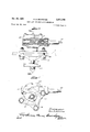
- Figure 6 is an enlarged fragmentary plan view of the hood latch mechanism at one side of the vehicle and with certain parts broken away and in section;
- Figure 7 is a fragmentary side elevational view of the structure of Figure 6;
- Figure 8 is a fragmentary transverse sectional view taken generally along the line VIII-VIII of Figure 6;
- Figure 9 is a fragmentary longitudinal sectional view illustrating certain details of the hood lift mechanism shown in Figures 2 and 4;
- Figure 10 is a fragmentary longitudinal sectional view illustrating somewhat schematically the disposition of the hood lift and latch mechanism within the vehicle.
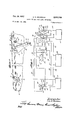
- Figure 11 is a schematic electric circuit diagram illustrating the manner in which the hood lift and latch may be coordinated for operation by a single control.
- the present invention relates particularly to a lift and latch mechanism for the hood 10 of an automotive vehicle 11.
- the lift mechanism indicated generally at 12 may be disposed at each side of the hood at the rear thereof, while the ice 2 latch mechanism indicated generally at 13 may be disposed at each side of the hood generally at the front thereof. Since the lift and latch mechanisms at each side of the vehicle are generally similar, the mechanism at only one side need be described in detail, and corresponding reference numerals have been applied to the similar parts.
- the hood lift mechanism 12 includes a mounting bracket 16 which may be carried at the interior of the vehicle 11 in any suitable manner.
- the bracket 16 is connected with the hood 10 by means of a linkage which is constructed to move the rear edge of the hood forwardly a limited amount during upward pivoting of the hood.
- the linkage includes a first link 20 pivotally secured to the bracket 16 by means of a shaft 21 and pivotally connected to the hood by means of a pivot pin 23 and a lug 24 of bracket 25 on the interior of the hood 10.
- a rocker link 27 is pivoted to the bracket 16 on a shaft 28 and is connected to a second lug 30 on hood bracket 25 by means of an intermediate link 32.
- a connector link 34 is provided which pivots the linkage 2! as the linkage 27, 32 is operated.
- a suitable power lift mechanism indicated generally at 40 is connected between a lug 41 on the bracket 16 and the intermediate link 32, the power means being extensible to raise the hood to the position indicated in Figure 4.
- the extensible power means 40 is preferably of the type which, is arranged to automatically stop at its extreme open and closed positions even though the drive motor therefor continues to operate.
- a worm and worm gear housing 50 is secured to the bracket lug 41 by means of a pivot shaft 52.
- the gear housing is shown as having a worm 57 journaled therein meshing with and driving a worm gear 58 keyed or otherwise secured to a vertical shaft 59 journaled in the worm gear housing 50 on an anti-friction bearing 61.
- the shaft 59 is provided with an upper helically threaded portion 59a which rotates withthe worm gear 58 to extend an actuating sleeve or tube 63 pivotally connected to the intermediate link 32 by means of a shaft 64 at its upper end.
- an elongated sleeve or nut 68 which is suitably secured to the sleeve 63.
- a retainer cage 70 is interposed between the shaft 59a and the nut 68, and the nut 68 is shown as having a plurality of spaced concentric annular grooves 72 therein receiving balls 74 carried in apertures 76 of the retainer cage 70.
- the apertures 76 are spaced along the cage 70 and are offset with respect to each other to correspond to the lead of the helical thread of shaft 59a.
- the balls 74 engage in the helical groove of shaft 59a so that rotation of the shaft raises nut 68 through the medium of balls 74.
- the cage 70 has a stop notch or lug 80 at its lower end, which is engageable with a stop pin 77 ( Figures 2 and 4) projecting from the shaft 59a within one of the threads thereof.
- the stop pin serves to rotate the cage 70 with the shaft 59a at the lower extreme end of travel of the nut 68 along the shaft, thus causing the balls 74 to travel around the annular concentric grooves 72 and stopping rectilinear movement of the tube 63 along the shaft 59a in spiteof continued rotation of the shaft.
- a notch 82 engageable with a stop pin 83 at the upper end of the shaft 59a for rotating the retainer cage 70 with the shaft 59a at the upper limit of travel of the nut 68 along the shaft.
- the pin 83 thus serves to stop travel of the tube 63 along the shaft when the hood of the vehicle is in fully opened position as shown in Figure 4, while the pin 77 serves to stop travel of the tube 63 along the shaft when the hood of the vehicle is in fully closed position as shown in Figure 2, without attention from the operator.
- stop pins 77 and 83 when engaged with the respective notches 80 and 82, rotate the cage 70 and cause the balls 74 to travel in the annular concentric grooves 72 when the shaft 59a is rotating in one direction.
- notch 80 or 82 will move away from stop pin 77 or 83 respectively and the hood will .be raised or lowered in accordance with the new direction of rotation.
- a motor 90 is shown in Figure l as being carried in the vehicle under the hood 10.
- the motor 90 may be a suitable reversible electric motor and is shown as driving flexible shafts 91 and 92 from opposite ends thereof.
- the flexible shaft 91 is shown as being cased in a sheath 93 and as driving the hood lift mechanism 12 at one side of the vehicle, while flexible shaft 92 is of course coupled to a complementary lift mechanism at the other side of the vehicle.
- an auxiliary drive shaft 95 is provided which is coupled directly to one lift mechanism 12 at the worm 57 thereof and is adapted to drive the other lift mechanism through the last mentioned worm 57, the drive shaft 91, the rotor of the motor 90, the drive shaft 92 and the corresponding worm 57 of the other lift mechanism.
- the flexible shaft 95 may be normally disengaged from the adjacent worm 57 and be engageable therewith.
- Housing 96 may enclose a suitable coupling mechanism so that shaft 95 may be driven by a crank or electric rotary power tool such as an electric drill.
- the housing 96 is of course positioned so as to provide convenient access under emergency conditions, for example from within the passenger space of the motor vehicle.
- the hood latching mechanism 13 may comprise a latch pin such as 100 in Figure on each side of the hood at the front thereof carried by a hood bracket 101 and cooperating with a latch member 103 carried on a bracket 104 secured to the vehicle body 11.
- the pin 100 is carried by means of a bracket 110
- the latch 103 is carried on a shaft 111 rotatably journalecl in a housing 112 secured with the bracket 104 by means of bolts 114.
- shaft 111 carries a worm gear 116 which is suitably keyed thereto and is driven by a worm shaft 117.
- the worm shafts 117 of the latch mechanisms may in turn be driven by flexible shafts 120 and 123 extending from opposite ends of the rotor of a conventional reversible electric motor 121 which may also be carried by the vehicle under the hood 10.
- An auxiliary drive flexible shaft 125 may be provided for emergency operation of the hood latch mechanism in case of a power failure and the shaft 125 may be driven through suitable gears within a housing 126 by means of a crank or portable power tool as described in conjunction with the auxiliary shaft 95 for the hood lift mechanism.
- FIG. 11 a schematic electric circuit for coordinating the operation of the hood latch and lift is illustrated in Figure 11.
- the actuating rod 130 is retracted to make contacts 131a, 131b, 132a, 132b, and 133a, 1331).
- a IClOSBd circuit then extends from one terminal of battery 135 through conductor 136, contacts 133a, 133b, conductor 138, switch arm 139, contact 140, conductor 141 to one terminal of the latch motor 121.
- the circuit is completed to the other terminal of the battery 135 through conductors 142, and 143, contacts 132b, 132a and conductor 145.
- the motor drives the latch mechanism to un1atch the hood.
- a portion of the latch 103 strikes an actuating rod 150 to snap the switch arm 139 to its lower position connecting with contact 151.
- the latch motor 121 is 7 4 then deenergized and the lift motor is energized to raise the hood through 136, 133a, 133b, 138, switch arm 139, contact 151, conductor 153 to one terminal of the lift motor 90 and from the other terminal of the motor 90 through conductor 154, contacts 131b, 131a and conductor 145 to the other terminal of the battery 135.
- the pin 83 strikes the notch 82 to prevent further travel of the nut 68.
- the actuating rod is then released to deenergize the motor 90.
- the actuating rod 130 is moved forwardly from its neutral position shown in Figure 11 to establish continuity between contacts 160a, 160b, 161a, 161b, and 162a, 16217.
- the rocker link 27 With the hood raised, the rocker link 27 will be in an inclined position as shown in Figure 4 so that contacts 165a, 165b will be closed and contacts 166a, 166b will be open, a lug 27a depending from the link 27 being diagramatically indicated as operating an actuating arm 167 having contactors controlling the contacts 165a, 165b and 166a, 1661;.
- a circuit is then closed to the latch motor 121 from one terminal of the battery 135 through conductor 145, contacts 161a, 161b, conductor 169, conductor 174, contacts 166b, 166a, conductor 176, contacts 178a, 17% of switch 179 (which is closed when the latch 103 is in unlatched position), and conductor 141 and from the other terminal of the latch motor 121 through conductor 142, contacts 1621;, 162a and conductor 136 to the other terminal of the battery 135.
- the latch motor 121 then moves the latch 103 to latching position, the latch 103 opening the switch 17 9 to deenergize the latch motor 121 when the latch has reached fully latched position.
- an enclosure covering raising mechanism having a two-directional drive motor with a covering framework to be raised and lowered, a stationary mounting bracket and an actuating mechanism connected between said stationary bracket and said framework for raising and lowering said framework and driven by said two-directional drive motor
- the improvement characterized by a linkage guiding said covering framework for bodily movement in a horizontal direction as said actuating mechanism pivots said covering framework upwardly
- the linkage including a first rocker link pivotally mounted intermediate its ends and having one end pivoted to said framework adjacent a margin of the framework and having an opposite end
- the linkage further including a second rocker link pivoted intermediate its ends and having one end connected to said opposite end of siad first rocker link, and a further link pivotally connected at one end to the other end of said second rocker link and at its other end to said framework remote from said margin, raising of the framework raising the other end of the'second rocker link to lower the other end of the first rocker link to raise said margin and simultaneously shift the margin horizontally.
- an enclosure covering raising mechanism having a two-directional drive motor with a covering framework to be raised and lowered, a stationary mounting bracket and an actuating mechanism connected between said stationary bracket and said framework for raising and lowering said framework and driven by said two-directional drive motor, the improvement characterized by a linkage guiding said covering framework for bodily movement in a horizontal direction as said actuating mechanism pivots said covering framework upwardly, a linkage including a first rocker link pivotally mounted intermediate its ends and having one end pivoted to said framework adjacent a margin of the framework and having an opposite end, the linkage further including a second rocker link pivoted intermediate its ends and having one end connected to said other end of said first rocker link, and a further link pivoted at one end to the other end of said second rocker link and at its other end to said framework remote from said margin, raising of the framework raising the other end of the second rocker link to lower the other end of the first rocker link to raise said margin and simultaneously shift the margin horizontally, and said actuating mechanism acting on said further link intermediate the ends
- an enclosure covering raising mechanism having a two-directional power means with a covering framework to be raised and lowered, a stationary mounting bracket and an actuating mechanism connected between said stationary bracket and said framework for raising and lowering said framework and driven by said power means, the improvement characterized by a linkage guiding said covering framework for bodily movement in a horizontal direction as said actuating mechanism pivots said covering framework upwardly, the linkage including a first rocker link pivotally mounted intermediate its ends and having one end pivoted to said framework adjacent a margin of the framework and having an opposite end, the linkage further including a second rocker link pivoted intermediate its ends and having one end connected to said other end of said first rocker link, and a further link pivoted at one end to the other end of said second rocker link and at its other end to said framework remote from said margin, raising of the framework raising the other end of the second rocker link to lower the other end of the first rocker link to raise said margin and simultaneously shift the margin horizontally, and said stationary mounting bracket pivotally carrying said first and second rocker links.
- a hood carried by the vehicle for movement between an open and a closed position, a hood lift mechanism connected adjacent one margin of the hood for pivoting the hood between open and closed positions, a hood latch mechanism located adjacent an opposite margin of the hood for latching the hood in closed position and for unlatching the hood to accommodate movement thereof to open position, electrically operated power means controlling and driving said hood lift and latch mechanisms, and limit switch means responsive to movements of said hood lift mechanism and said hood latch mechanism and coordinating operation of said hood lift and hood latch mechanisms by said electrically operated power means.
Landscapes
- Engineering & Computer Science (AREA)
- Mechanical Engineering (AREA)
- Lock And Its Accessories (AREA)
Description
1957 A. D. BRUNDAGE 2,811,348
HOOD LIFT AND HOOD LATCH MECHANISM Filed NOV. 22, 1954 7 Sheets-Sheet 1 Oct. 29, 1957 A. D. BRUNDAGE noon LIFT AND H001) LATCH MECHANISM 7 Sheets-Sheet 2 Filed Nov. 22, 1954 Oct. 29, 1957 A. D. BRUNDAGE HOOD LIFT AND HOOD LATCH MECHANISM 7 Sheets-Sheet 3 Filed Nov. 22, 1954 Oct. 29, 1957 A. D. BRUNDAGE HOOD LIFT AND HOOD LATCH MECHANISM 7 Sheets-Sheet 4 Filed Nov. 22, 1954 W mm Inyen ,42
Oct. 29, 1957 A. D. BRUNDAGE 2,811,348
HOOD LIFT AND noon LATCH MECHANISM Filed Nov. 22, 1954 7 Sheets-Sheet 5 LIVE .22: far A 44 fl flfUA/DAGE Oct. 1957 A. D. 'BRUNDAGE 2,811,348
HOOD LIFT AND HOOD LATCH MECHANISM Filed Nov. 22, 1954 '7 Sheets-Sheet 6 WWW #147 Get. 29, 1957 BRUNDAGE 2,811,348
HOOD LIFT AND HOOD LATCH MECHANISM Filed Nov. 22, 1954 '7 Sheets-Sheet 7 In -en 7271 A44, 2 5804 0462 United States Patent HOOD LET AND HOOD LATCH MECHANISM Alan D. Brundage, Birmingham, Mich., assignor to Houdaille Industries, Inc., a corporation of Michigan Application November 22, 1954, Serial No. 470,485
4 Claims. (Cl. 268-74) This invention relates to a power operated lift and latch mechanism for a closure member of an automotive vehicle, and more particularly relates to such a mechanism applied to the hood of an automotive vehicle wherein the lift and latch systems are coordinated to automatically unlatch and lift the hood or to automatically lower and latch the hood.
It is an important object of the present invention to provide means for power operation of the hood of an automotive vehicle.
Another object of the invention is to provide a coordinated power operated hood lift and latch mechanism for an automotive vehicle.
A further object of the present invention is to provide novel mechanism for controlling the raising and lowering and latching and unlatching of a closure member associated with an automotive vehicle.
Other objects, features and advantages of the present invention will be more fully apparent from the following detailed description taken in conjunction with the accompanying drawings, in which:
Figure 1 is a more or less schematic transverse sectional view illustrating the hood lifting mechanism according to the present invention;
Figure 2 is a fragmentary enlarged longitudinal sectional view taken generally along the line II-II of Figure 1;
Figure 3 is a fragmentary horizontal sectional view taken generally along the line IIIIII of Figure 2;
Figure 4 is a fragmentary longitudinal sectional view similar to Figure 2 but showing the hood lift mechanism in extended position with the hood raised;
Figure 5 is a more or less schematic horizontal sectional view illustrating the hood latching mechanism according to the present invention;
Figure 6 is an enlarged fragmentary plan view of the hood latch mechanism at one side of the vehicle and with certain parts broken away and in section;
Figure 7 is a fragmentary side elevational view of the structure of Figure 6;
Figure 8 is a fragmentary transverse sectional view taken generally along the line VIII-VIII of Figure 6;
Figure 9 is a fragmentary longitudinal sectional view illustrating certain details of the hood lift mechanism shown in Figures 2 and 4;
Figure 10 is a fragmentary longitudinal sectional view illustrating somewhat schematically the disposition of the hood lift and latch mechanism within the vehicle; and
Figure 11 is a schematic electric circuit diagram illustrating the manner in which the hood lift and latch may be coordinated for operation by a single control.
As shown on the drawings:
Referring to Figure 10 of the drawings, the present invention relates particularly to a lift and latch mechanism for the hood 10 of an automotive vehicle 11. The lift mechanism indicated generally at 12 may be disposed at each side of the hood at the rear thereof, while the ice 2 latch mechanism indicated generally at 13 may be disposed at each side of the hood generally at the front thereof. Since the lift and latch mechanisms at each side of the vehicle are generally similar, the mechanism at only one side need be described in detail, and corresponding reference numerals have been applied to the similar parts.
Referring particularly to Figures 1 through 4, it will be observed that the hood lift mechanism 12 includes a mounting bracket 16 which may be carried at the interior of the vehicle 11 in any suitable manner. The bracket 16 is connected with the hood 10 by means of a linkage which is constructed to move the rear edge of the hood forwardly a limited amount during upward pivoting of the hood. For moving the rear edge of the hood forwardly, the linkage includes a first link 20 pivotally secured to the bracket 16 by means of a shaft 21 and pivotally connected to the hood by means of a pivot pin 23 and a lug 24 of bracket 25 on the interior of the hood 10. For guiding the upward pivotal movement of the hood 10, a rocker link 27 is pivoted to the bracket 16 on a shaft 28 and is connected to a second lug 30 on hood bracket 25 by means of an intermediate link 32. To effect simultaneous operation of both linkages, a connector link 34 is provided which pivots the linkage 2!) as the linkage 27, 32 is operated. For raising and lowering the hood 10, a suitable power lift mechanism indicated generally at 40 is connected between a lug 41 on the bracket 16 and the intermediate link 32, the power means being extensible to raise the hood to the position indicated in Figure 4.
The extensible power means 40 is preferably of the type which, is arranged to automatically stop at its extreme open and closed positions even though the drive motor therefor continues to operate. As herein shown, a worm and worm gear housing 50 is secured to the bracket lug 41 by means of a pivot shaft 52. The gear housing is shown as having a worm 57 journaled therein meshing with and driving a worm gear 58 keyed or otherwise secured to a vertical shaft 59 journaled in the worm gear housing 50 on an anti-friction bearing 61. The shaft 59 is provided with an upper helically threaded portion 59a which rotates withthe worm gear 58 to extend an actuating sleeve or tube 63 pivotally connected to the intermediate link 32 by means of a shaft 64 at its upper end. At the lower end of the tube 63 is an elongated sleeve or nut 68 which is suitably secured to the sleeve 63. A retainer cage 70, Figure 9, is interposed between the shaft 59a and the nut 68, and the nut 68 is shown as having a plurality of spaced concentric annular grooves 72 therein receiving balls 74 carried in apertures 76 of the retainer cage 70. The apertures 76 are spaced along the cage 70 and are offset with respect to each other to correspond to the lead of the helical thread of shaft 59a. The balls 74 engage in the helical groove of shaft 59a so that rotation of the shaft raises nut 68 through the medium of balls 74.
The cage 70 has a stop notch or lug 80 at its lower end, which is engageable with a stop pin 77 (Figures 2 and 4) projecting from the shaft 59a within one of the threads thereof. The stop pin serves to rotate the cage 70 with the shaft 59a at the lower extreme end of travel of the nut 68 along the shaft, thus causing the balls 74 to travel around the annular concentric grooves 72 and stopping rectilinear movement of the tube 63 along the shaft 59a in spiteof continued rotation of the shaft. At the upper end of the retainer cage 70 is a notch 82 engageable with a stop pin 83 at the upper end of the shaft 59a for rotating the retainer cage 70 with the shaft 59a at the upper limit of travel of the nut 68 along the shaft. The pin 83 thus serves to stop travel of the tube 63 along the shaft when the hood of the vehicle is in fully opened position as shown in Figure 4, while the pin 77 serves to stop travel of the tube 63 along the shaft when the hood of the vehicle is in fully closed position as shown in Figure 2, without attention from the operator.
It will be understood that the stop pins 77 and 83, when engaged with the respective notches 80 and 82, rotate the cage 70 and cause the balls 74 to travel in the annular concentric grooves 72 when the shaft 59a is rotating in one direction. However, as soon as the direction of rotation of the shaft 59a is reversed, notch 80 or 82 will move away from stop pin 77 or 83 respectively and the hood will .be raised or lowered in accordance with the new direction of rotation.
Referring now to the drive means for the worm 57, a motor 90 is shown in Figure l as being carried in the vehicle under the hood 10. The motor 90 may be a suitable reversible electric motor and is shown as driving flexible shafts 91 and 92 from opposite ends thereof. The flexible shaft 91 is shown as being cased in a sheath 93 and as driving the hood lift mechanism 12 at one side of the vehicle, while flexible shaft 92 is of course coupled to a complementary lift mechanism at the other side of the vehicle.
To provide for emergency operation of the hood lift in case of a power failure, an auxiliary drive shaft 95 is provided which is coupled directly to one lift mechanism 12 at the worm 57 thereof and is adapted to drive the other lift mechanism through the last mentioned worm 57, the drive shaft 91, the rotor of the motor 90, the drive shaft 92 and the corresponding worm 57 of the other lift mechanism. The flexible shaft 95 may be normally disengaged from the adjacent worm 57 and be engageable therewith. Housing 96 may enclose a suitable coupling mechanism so that shaft 95 may be driven by a crank or electric rotary power tool such as an electric drill. The housing 96 is of course positioned so as to provide convenient access under emergency conditions, for example from within the passenger space of the motor vehicle.
Referring now to Figures through 8, the hood latching mechanism 13 may comprise a latch pin such as 100 in Figure on each side of the hood at the front thereof carried by a hood bracket 101 and cooperating with a latch member 103 carried on a bracket 104 secured to the vehicle body 11. As seen in Figure 8, the pin 100 is carried by means of a bracket 110, while the latch 103 is carried on a shaft 111 rotatably journalecl in a housing 112 secured with the bracket 104 by means of bolts 114. Within the housing 112, shaft 111 carries a worm gear 116 which is suitably keyed thereto and is driven by a worm shaft 117. As seen in Figure 5, the worm shafts 117 of the latch mechanisms may in turn be driven by flexible shafts 120 and 123 extending from opposite ends of the rotor of a conventional reversible electric motor 121 which may also be carried by the vehicle under the hood 10. An auxiliary drive flexible shaft 125 may be provided for emergency operation of the hood latch mechanism in case of a power failure and the shaft 125 may be driven through suitable gears within a housing 126 by means of a crank or portable power tool as described in conjunction with the auxiliary shaft 95 for the hood lift mechanism.
By way of illustrative example, a schematic electric circuit for coordinating the operation of the hood latch and lift is illustrated in Figure 11. For unlatching the latch 103 and raising the hood, the actuating rod 130 is retracted to make contacts 131a, 131b, 132a, 132b, and 133a, 1331). A IClOSBd circuit then extends from one terminal of battery 135 through conductor 136, contacts 133a, 133b, conductor 138, switch arm 139, contact 140, conductor 141 to one terminal of the latch motor 121. The circuit is completed to the other terminal of the battery 135 through conductors 142, and 143, contacts 132b, 132a and conductor 145. With this polarity of energization of the motor 121, the motor drives the latch mechanism to un1atch the hood. At the end of the unlatching movement of the latch 103 indicated schematically in Figure 11, a portion of the latch 103 strikes an actuating rod 150 to snap the switch arm 139 to its lower position connecting with contact 151. The latch motor 121 is 7 4 then deenergized and the lift motor is energized to raise the hood through 136, 133a, 133b, 138, switch arm 139, contact 151, conductor 153 to one terminal of the lift motor 90 and from the other terminal of the motor 90 through conductor 154, contacts 131b, 131a and conductor 145 to the other terminal of the battery 135. When the power lift device 40 reaches its fully extended position as shown in Figure 9, the pin 83 strikes the notch 82 to prevent further travel of the nut 68. The actuating rod is then released to deenergize the motor 90.
It now it is desired to lower the hood 10, the actuating rod 130 is moved forwardly from its neutral position shown in Figure 11 to establish continuity between contacts 160a, 160b, 161a, 161b, and 162a, 16217. With the hood raised, the rocker link 27 will be in an inclined position as shown in Figure 4 so that contacts 165a, 165b will be closed and contacts 166a, 166b will be open, a lug 27a depending from the link 27 being diagramatically indicated as operating an actuating arm 167 having contactors controlling the contacts 165a, 165b and 166a, 1661;. Under these conditions, reverse polarity is applied to the hood lift motor 90, the circuit extending from through contacts 161a, 161b, conductor 169, contacts 1650, 165b and conductor 170 to one terminal of the motor 90 and from the other terminal of the motor 90 through conductor 154, contacts b, 160a and conductor 136 to the other terminal of the battery 135. When the hood 10 is in fully closed position, the rocker link 27 operates the actuator bar 167 to snap contacts a, 1651) open and contacts 166a, 166b closed. A circuit is then closed to the latch motor 121 from one terminal of the battery 135 through conductor 145, contacts 161a, 161b, conductor 169, conductor 174, contacts 166b, 166a, conductor 176, contacts 178a, 17% of switch 179 (which is closed when the latch 103 is in unlatched position), and conductor 141 and from the other terminal of the latch motor 121 through conductor 142, contacts 1621;, 162a and conductor 136 to the other terminal of the battery 135. The latch motor 121 then moves the latch 103 to latching position, the latch 103 opening the switch 17 9 to deenergize the latch motor 121 when the latch has reached fully latched position.
It will be understood that modifications and variations may be effected without departing from the scope of the novel concepts of the present invention.
I claim as my invention:
1. In an enclosure covering raising mechanism having a two-directional drive motor with a covering framework to be raised and lowered, a stationary mounting bracket and an actuating mechanism connected between said stationary bracket and said framework for raising and lowering said framework and driven by said two-directional drive motor, the improvement characterized by a linkage guiding said covering framework for bodily movement in a horizontal direction as said actuating mechanism pivots said covering framework upwardly, the linkage including a first rocker link pivotally mounted intermediate its ends and having one end pivoted to said framework adjacent a margin of the framework and having an opposite end, the linkage further including a second rocker link pivoted intermediate its ends and having one end connected to said opposite end of siad first rocker link, and a further link pivotally connected at one end to the other end of said second rocker link and at its other end to said framework remote from said margin, raising of the framework raising the other end of the'second rocker link to lower the other end of the first rocker link to raise said margin and simultaneously shift the margin horizontally.
2. In an enclosure covering raising mechanism having a two-directional drive motor with a covering framework to be raised and lowered, a stationary mounting bracket and an actuating mechanism connected between said stationary bracket and said framework for raising and lowering said framework and driven by said two-directional drive motor, the improvement characterized by a linkage guiding said covering framework for bodily movement in a horizontal direction as said actuating mechanism pivots said covering framework upwardly, a linkage including a first rocker link pivotally mounted intermediate its ends and having one end pivoted to said framework adjacent a margin of the framework and having an opposite end, the linkage further including a second rocker link pivoted intermediate its ends and having one end connected to said other end of said first rocker link, and a further link pivoted at one end to the other end of said second rocker link and at its other end to said framework remote from said margin, raising of the framework raising the other end of the second rocker link to lower the other end of the first rocker link to raise said margin and simultaneously shift the margin horizontally, and said actuating mechanism acting on said further link intermediate the ends thereof for raising said covering framework.
3. In an enclosure covering raising mechanism having a two-directional power means with a covering framework to be raised and lowered, a stationary mounting bracket and an actuating mechanism connected between said stationary bracket and said framework for raising and lowering said framework and driven by said power means, the improvement characterized by a linkage guiding said covering framework for bodily movement in a horizontal direction as said actuating mechanism pivots said covering framework upwardly, the linkage including a first rocker link pivotally mounted intermediate its ends and having one end pivoted to said framework adjacent a margin of the framework and having an opposite end, the linkage further including a second rocker link pivoted intermediate its ends and having one end connected to said other end of said first rocker link, and a further link pivoted at one end to the other end of said second rocker link and at its other end to said framework remote from said margin, raising of the framework raising the other end of the second rocker link to lower the other end of the first rocker link to raise said margin and simultaneously shift the margin horizontally, and said stationary mounting bracket pivotally carrying said first and second rocker links.
4. In a motor vehicle, a hood carried by the vehicle for movement between an open and a closed position, a hood lift mechanism connected adjacent one margin of the hood for pivoting the hood between open and closed positions, a hood latch mechanism located adjacent an opposite margin of the hood for latching the hood in closed position and for unlatching the hood to accommodate movement thereof to open position, electrically operated power means controlling and driving said hood lift and latch mechanisms, and limit switch means responsive to movements of said hood lift mechanism and said hood latch mechanism and coordinating operation of said hood lift and hood latch mechanisms by said electrically operated power means.
References Cited in the file of this patent UNITED STATES PATENTS Re. 21,775 Falcon Apr. 22, 1941 1,002,029 Brown Aug. 29, 1911 1,002,030 Brown Aug. 29, 1911 1,151,479 Kurtz Aug. 24, 1915 1,367,931 Varnum Feb. 8, 1921 1,631,508 Wagner June 7, 1927 1,943,927 Phillips Jan. 16, 1934 2,190,297 Salkvist Feb. 13, 1940 2,366,734 Lear Jan. 9, 1945 2,479,713 Beach Aug. 23, 1949 2,535,600 Rappl Dec. 26, 1950 2,541,288 Rice Feb. 13, 1951 2,553,023 Walters May 15, 1951 2,558,867 May et al July 3, 1951 2,594,643 Gustisha Apr. 29, 1952
Priority Applications (1)
| Application Number | Priority Date | Filing Date | Title |
|---|---|---|---|
| US470485A US2811348A (en) | 1954-11-22 | 1954-11-22 | Hood lift and hood latch mechanism |
Applications Claiming Priority (1)
| Application Number | Priority Date | Filing Date | Title |
|---|---|---|---|
| US470485A US2811348A (en) | 1954-11-22 | 1954-11-22 | Hood lift and hood latch mechanism |
Publications (1)
| Publication Number | Publication Date |
|---|---|
| US2811348A true US2811348A (en) | 1957-10-29 |
Family
ID=23867806
Family Applications (1)
| Application Number | Title | Priority Date | Filing Date |
|---|---|---|---|
| US470485A Expired - Lifetime US2811348A (en) | 1954-11-22 | 1954-11-22 | Hood lift and hood latch mechanism |
Country Status (1)
| Country | Link |
|---|---|
| US (1) | US2811348A (en) |
Cited By (9)
| Publication number | Priority date | Publication date | Assignee | Title |
|---|---|---|---|---|
| US3022108A (en) * | 1960-06-17 | 1962-02-20 | Gen Motors Corp | Power-actuated tail gate |
| EP0361020A1 (en) * | 1988-09-23 | 1990-04-04 | Techform Products Ltd. | Dual motion closure deck lid hinge |
| DE4124869A1 (en) * | 1991-07-26 | 1993-01-28 | Bayerische Motoren Werke Ag | Motorised drive esp. for tailgate of motor vehicle - is geared to spring-balanced gate with overload safety coupling and compact piston in cylinder guide |
| EP0757149A1 (en) * | 1995-08-02 | 1997-02-05 | W. HAUTAU GmbH | Stay with electrically powered checking lever |
| WO2001081699A1 (en) * | 2000-04-20 | 2001-11-01 | Edscha Ag | Drivable flap hinge |
| EP1072747A3 (en) * | 1999-07-28 | 2001-11-21 | Volkswagen Aktiengesellschaft | Actuator for the motorized swinging of a front door or a tailgate of a vehicle |
| WO2003076750A1 (en) * | 2002-03-08 | 2003-09-18 | Campisa S.R.L. | Emergency device for electric motors of electrohydraulic and electromechanical apparatuses |
| DE19616299B4 (en) * | 1996-04-25 | 2004-03-04 | Siemens Ag | Closing or opening aid for a closing part |
| EP1520952A1 (en) * | 2003-10-01 | 2005-04-06 | Stabilus GmbH | Bonnet closing device for vehicles |
Citations (15)
| Publication number | Priority date | Publication date | Assignee | Title |
|---|---|---|---|---|
| US1002030A (en) * | 1909-03-12 | 1911-08-29 | Nat Pneumatic Co | Door-operating mechanism. |
| US1002029A (en) * | 1909-03-12 | 1911-08-29 | Nat Pneumatic Co | Pneumatic door-operating mechanism. |
| US1151479A (en) * | 1914-05-05 | 1915-08-24 | Karl Wm Kurtz | Electric door unlocking and opening and closing means for automobiles. |
| US1367931A (en) * | 1918-11-29 | 1921-02-08 | George B Varnum | Gate-engine |
| US1631508A (en) * | 1926-07-01 | 1927-06-07 | Wagner Richard | Automobile hood latch |
| US1943927A (en) * | 1931-04-16 | 1934-01-16 | Bassick Co | Fastening for automobile hoods |
| US2190297A (en) * | 1937-03-06 | 1940-02-13 | Koppers Co Inc | Coke-oven door operating mechanism |
| USRE21775E (en) * | 1938-03-24 | 1941-04-22 | falcon | |
| US2366734A (en) * | 1943-06-09 | 1945-01-09 | Lear Avia Inc | Multiple actuator system |
| US2479713A (en) * | 1947-12-13 | 1949-08-23 | Lockheed Aircraft Corp | Canopy control and jettisoning mechanism |
| US2535600A (en) * | 1947-06-14 | 1950-12-26 | Trico Products Corp | Motor vehicle luggage compartment closure operating mechanism |
| US2541288A (en) * | 1946-03-08 | 1951-02-13 | Clifford M Rice | Residential motor coach |
| US2553023A (en) * | 1947-02-25 | 1951-05-15 | Walters John | Automatic door opener |
| US2558867A (en) * | 1948-04-20 | 1951-07-03 | Westinghouse Air Brake Co | Door operating mechanism |
| US2594643A (en) * | 1950-06-16 | 1952-04-29 | Edward F Gustisha | Vehicle trunk lid control |
-
1954
- 1954-11-22 US US470485A patent/US2811348A/en not_active Expired - Lifetime
Patent Citations (15)
| Publication number | Priority date | Publication date | Assignee | Title |
|---|---|---|---|---|
| US1002030A (en) * | 1909-03-12 | 1911-08-29 | Nat Pneumatic Co | Door-operating mechanism. |
| US1002029A (en) * | 1909-03-12 | 1911-08-29 | Nat Pneumatic Co | Pneumatic door-operating mechanism. |
| US1151479A (en) * | 1914-05-05 | 1915-08-24 | Karl Wm Kurtz | Electric door unlocking and opening and closing means for automobiles. |
| US1367931A (en) * | 1918-11-29 | 1921-02-08 | George B Varnum | Gate-engine |
| US1631508A (en) * | 1926-07-01 | 1927-06-07 | Wagner Richard | Automobile hood latch |
| US1943927A (en) * | 1931-04-16 | 1934-01-16 | Bassick Co | Fastening for automobile hoods |
| US2190297A (en) * | 1937-03-06 | 1940-02-13 | Koppers Co Inc | Coke-oven door operating mechanism |
| USRE21775E (en) * | 1938-03-24 | 1941-04-22 | falcon | |
| US2366734A (en) * | 1943-06-09 | 1945-01-09 | Lear Avia Inc | Multiple actuator system |
| US2541288A (en) * | 1946-03-08 | 1951-02-13 | Clifford M Rice | Residential motor coach |
| US2553023A (en) * | 1947-02-25 | 1951-05-15 | Walters John | Automatic door opener |
| US2535600A (en) * | 1947-06-14 | 1950-12-26 | Trico Products Corp | Motor vehicle luggage compartment closure operating mechanism |
| US2479713A (en) * | 1947-12-13 | 1949-08-23 | Lockheed Aircraft Corp | Canopy control and jettisoning mechanism |
| US2558867A (en) * | 1948-04-20 | 1951-07-03 | Westinghouse Air Brake Co | Door operating mechanism |
| US2594643A (en) * | 1950-06-16 | 1952-04-29 | Edward F Gustisha | Vehicle trunk lid control |
Cited By (12)
| Publication number | Priority date | Publication date | Assignee | Title |
|---|---|---|---|---|
| US3022108A (en) * | 1960-06-17 | 1962-02-20 | Gen Motors Corp | Power-actuated tail gate |
| EP0361020A1 (en) * | 1988-09-23 | 1990-04-04 | Techform Products Ltd. | Dual motion closure deck lid hinge |
| DE4124869A1 (en) * | 1991-07-26 | 1993-01-28 | Bayerische Motoren Werke Ag | Motorised drive esp. for tailgate of motor vehicle - is geared to spring-balanced gate with overload safety coupling and compact piston in cylinder guide |
| EP0757149A1 (en) * | 1995-08-02 | 1997-02-05 | W. HAUTAU GmbH | Stay with electrically powered checking lever |
| DE19616299B4 (en) * | 1996-04-25 | 2004-03-04 | Siemens Ag | Closing or opening aid for a closing part |
| EP1072747A3 (en) * | 1999-07-28 | 2001-11-21 | Volkswagen Aktiengesellschaft | Actuator for the motorized swinging of a front door or a tailgate of a vehicle |
| WO2001081699A1 (en) * | 2000-04-20 | 2001-11-01 | Edscha Ag | Drivable flap hinge |
| US6789834B2 (en) | 2000-04-20 | 2004-09-14 | Edscha Ag | Drivable flap hinge |
| WO2003076750A1 (en) * | 2002-03-08 | 2003-09-18 | Campisa S.R.L. | Emergency device for electric motors of electrohydraulic and electromechanical apparatuses |
| EP1520952A1 (en) * | 2003-10-01 | 2005-04-06 | Stabilus GmbH | Bonnet closing device for vehicles |
| US20050121940A1 (en) * | 2003-10-01 | 2005-06-09 | Stabilus Gmbh | Closing unit |
| US7290823B2 (en) | 2003-10-01 | 2007-11-06 | Stabilus Gmbh | Closing unit |
Similar Documents
| Publication | Publication Date | Title |
|---|---|---|
| US2811348A (en) | Hood lift and hood latch mechanism | |
| US5483769A (en) | Door drive equipment for mass transit vehicle | |
| JP5841950B2 (en) | Lift gate opening and closing device | |
| US3289350A (en) | Garage door operators | |
| US4702511A (en) | Tailgate closure mechanism | |
| US2893727A (en) | Power actuated closures | |
| US2719036A (en) | Deck lid lifting mechanism | |
| US2780458A (en) | Louvered window and operating means therefor for vehicle doors | |
| US3320698A (en) | Apparatus for opening and closing, respectively, windows and hatches on boats | |
| US3022108A (en) | Power-actuated tail gate | |
| CN101992838B (en) | Operating mechanism of loading hatch of cargo ship | |
| GB1428141A (en) | Sliding door mechanism | |
| US3900965A (en) | Sequential dual window operating mechanism | |
| US3004757A (en) | Power-actuated tail gate | |
| CN212924051U (en) | Electric door opening machine and electric vertical hinged door | |
| CN108407582A (en) | A kind of arrangements for automotive doors and skylight open system | |
| US5024022A (en) | Automobile window opening and closing device | |
| US1927559A (en) | Elevator door operating mechanism | |
| JPH0671852U (en) | Vehicle door opening and closing device | |
| US6035579A (en) | Rack and pinion window regulator | |
| US2993731A (en) | Header lock | |
| CN211691114U (en) | Full-automatic sunshine roof window intelligence switching system | |
| US2332731A (en) | Power operated window begulator | |
| CN112389549A (en) | Cover plate translational hidden opening mechanism | |
| EP0234701A2 (en) | Tailgate closure mechanism |