US2803948A - Integral drain tile unit - Google Patents
Integral drain tile unit Download PDFInfo
- Publication number
- US2803948A US2803948A US431719A US43171954A US2803948A US 2803948 A US2803948 A US 2803948A US 431719 A US431719 A US 431719A US 43171954 A US43171954 A US 43171954A US 2803948 A US2803948 A US 2803948A
- Authority
- US
- United States
- Prior art keywords
- unit
- drain
- tile
- drain tile
- units
- Prior art date
- Legal status (The legal status is an assumption and is not a legal conclusion. Google has not performed a legal analysis and makes no representation as to the accuracy of the status listed.)
- Expired - Lifetime
Links
- XLYOFNOQVPJJNP-UHFFFAOYSA-N water Substances O XLYOFNOQVPJJNP-UHFFFAOYSA-N 0.000 description 8
- 238000009434 installation Methods 0.000 description 4
- 239000000463 material Substances 0.000 description 3
- 239000002689 soil Substances 0.000 description 3
- 230000008595 infiltration Effects 0.000 description 2
- 238000001764 infiltration Methods 0.000 description 2
- 239000011270 tar paper Substances 0.000 description 2
- 238000010521 absorption reaction Methods 0.000 description 1
- 239000004927 clay Substances 0.000 description 1
- 238000004140 cleaning Methods 0.000 description 1
- 230000000694 effects Effects 0.000 description 1
- 230000008030 elimination Effects 0.000 description 1
- 238000003379 elimination reaction Methods 0.000 description 1
- 239000004519 grease Substances 0.000 description 1
- 238000004519 manufacturing process Methods 0.000 description 1
- 229920000136 polysorbate Polymers 0.000 description 1
- 238000010561 standard procedure Methods 0.000 description 1
Images

Classifications
-
- C—CHEMISTRY; METALLURGY
- C02—TREATMENT OF WATER, WASTE WATER, SEWAGE, OR SLUDGE
- C02F—TREATMENT OF WATER, WASTE WATER, SEWAGE, OR SLUDGE
- C02F3/00—Biological treatment of water, waste water, or sewage
- C02F3/02—Aerobic processes
- C02F3/04—Aerobic processes using trickle filters
- C02F3/046—Soil filtration
-
- Y—GENERAL TAGGING OF NEW TECHNOLOGICAL DEVELOPMENTS; GENERAL TAGGING OF CROSS-SECTIONAL TECHNOLOGIES SPANNING OVER SEVERAL SECTIONS OF THE IPC; TECHNICAL SUBJECTS COVERED BY FORMER USPC CROSS-REFERENCE ART COLLECTIONS [XRACs] AND DIGESTS
- Y02—TECHNOLOGIES OR APPLICATIONS FOR MITIGATION OR ADAPTATION AGAINST CLIMATE CHANGE
- Y02W—CLIMATE CHANGE MITIGATION TECHNOLOGIES RELATED TO WASTEWATER TREATMENT OR WASTE MANAGEMENT
- Y02W10/00—Technologies for wastewater treatment
- Y02W10/10—Biological treatment of water, waste water, or sewage
Definitions
- the present invention relates to novel units for use in drainage systems such as systems for the disposal of efiluent water from septic tanks, grease traps, etc.
- the invention is also suitable for use in draining water from other sources.
- the overflow water is frequently conducted through drain tile down a gentle slope to porous soil under gravel beds, to effect dissipation ofthe effiuent water into the soil.
- the drain tile sections have their ends spaced slightly apart to allow the water to leak between such ends into the absorption bed.
- the tile sections are embedded into the gravel over the porous soil, and there is infiltration of dirt between the ends of the tile sections, so that trouble is frequently encountered through clogging of the drain tile, presence of roots, etc. Even where no such infiltration of dirt occurs, there is obstruction to free flow of water through the spaces be tween the ends of the pipes or tile sections, because of close proximity of the gravel or the like in which the drain tile is embedded. This normally is partly prevented by placing pieces of tar paper over the joints which causes added expense of labor and material.
- One of the objects of the present invention is to provide a structure which will be a single unit and overcome a number of the above objections to the standard method of laying a drain field for septic tanks.
- Another object of the present invention is to provide a drain tile unit which is considerably more efficient than the standard drain field tile so that a considerably smaller area can be used for the septic tank field than is normally the case.
- a further object of the present invention is to provide a drain tile unit into which the roots of trees and plants will not normally grow so as to clog the field.
- An additional object is to provide a drain field unit which will accomplish substantial economy in labor and material over the conventional drain field.
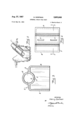
- Figure l is a perspective view of one form of my invention.
- Figure 2 is a plan view in partial cross section along lines 22 and X-X of Figure 1.
- Figure 3 is an elevational cross section view taken along line 3-3 of Figure 4.
- Figure 4 is a plan view in partial cross section along lines 44 of Figure 3.
- Figure 5 is a perspective view showing my units as they are placed in a trench in the field.
- the unit designated in general by 1 consists essentially of side walls 2, end walls 3, and open bottom 4, a top portion consisting of a cylindrical member 5 and top walls 6.
- the cylindrical member 5 is perforated by a series of cylindrical holes 7 which are in a vertical plane, that is, the center lines of holes 7 are parallel to side walls 2.
- the said holes 7 are in two rows, symmetrically spaced with respect to the center line of the cylindrical member 5.
- Side walls 2 and end walls 3 are imperforate.
- the holes 7 may be tapered from top to bottom, i. e., slightly larger diameter at the bottom than the top in order to facilitate fabrication and minimize possibility of clogging.
- FIG. 3 Another form of my invention is shown in Figure 3.
- the unit has side walls 8 and end walls 9.
- the cylin drical member 10 has slots 11 positioned about the middle of the cylindrical member 10. Side walls 8 and end walls 9 are imperforate. Slots 11 are preferably tapered as shown in Figure 3.
- Either type of unit can be used in accordance with my invention, but unit 1 with holes 7 is the preferred form of the invention and is more satisfactory in use.
- the unit 1 as shown in Figures 1 and 2, or the unit 12, as shown in Figures 3 and 4 are placed in a standard trench and each unit is butted end to end with no appreciable space between them, as shown in Figure 5.
- the efiluent from the septic tank flows through the hollow cylindrical shaped member 5 or 10, depending on which type of unit is used and in the case unit 1,,such as shown in Figures 1 and 2, is used, the effluent falls through the holes 7 to the empty space or dry well below. It then seeps directly into the ground since the units have no bottom.
- case unit 12 such as shown in Figures 3 and 4 is used, the efliuent falls through the slots 11 into the empty space or dry well below.
- the imperforate end walls 3 and 9 of the unit serve to keep the dry wells of each unit separate from the other so as to prevent the water running from one dry well to the next too rapidly and assures maximum uniform seepage into the ground along the whole length of the drain line.
- the imperforate walls and integral structure of my unit lend unusual strength to the unit so that large surface loads will not disturb it. My unit is'also much cheaper to produce than separate units of the prior art, and also cheaper and easier to handle.
- a pre-cast drain tile for septic tank and the like drainage systems said tile being formed with an integral rectangular chamber open at the bottom and including upstanding side and end walls surrounding said chamber, a top wall and an open ended drain pipe section forming a part of said top Wall and terminating flush with the outer faces of said end walls, the said pipe section having perforations opening into said chamber, said perforations being at the bottom of said pipe section and being tapered downwardly with the larger end at the bottom, said sidewalls, end walls and top wall except for said pipe section, being imperforate.
- each of said units consisting of a title being formed with an integral rectangular chamber open at the bottom and including upstanding side and end walls surrounding said chamber, a top wall and an open ended drain pipe section forming a part of said top Wall and terminating flush with the outer faces of said end walls, the said pipe section having perforations opening into said chamber, said perforations being at the bottom of said pipe section and being tapered downwardly with the larger end at the bottom, said sidewalls, end walls and top wall except for said pipe section, being imperforate.
Landscapes
- Life Sciences & Earth Sciences (AREA)
- Biodiversity & Conservation Biology (AREA)
- Microbiology (AREA)
- Hydrology & Water Resources (AREA)
- Engineering & Computer Science (AREA)
- Environmental & Geological Engineering (AREA)
- Water Supply & Treatment (AREA)
- Chemical & Material Sciences (AREA)
- Organic Chemistry (AREA)
- Treatment Of Biological Wastes In General (AREA)
Description
Aug. 27, 1957 H. DORFMAN 2,803,943
INTEGRAL DRAIN TILE UNIT Filed May 24. 1954 1 2 Sheets-Sheet 1 INVENT 1; Harry 00/- man Aug. 27, 1957 H. DORFMAN INTEGRAL DRAIN TILE UNIT 2 Sheets-Sheet 2 Filed May 24. 1954 INVENTOR. Harry Dorfmcm Afiorneu United States Patent 6 INTEGRAL DRAIN TILE UNIT Harry Dorfman, Miami Beach, Fla. Application May 24,1954, Serial No. 431,719
2 Claims. (Cl. 61-11) The present invention relates to novel units for use in drainage systems such as systems for the disposal of efiluent water from septic tanks, grease traps, etc. The invention is also suitable for use in draining water from other sources.
In the draining of comparatively clear water from septic tanks and the like, the overflow water is frequently conducted through drain tile down a gentle slope to porous soil under gravel beds, to effect dissipation ofthe effiuent water into the soil. Usually the drain tile sections have their ends spaced slightly apart to allow the water to leak between such ends into the absorption bed. The tile sections are embedded into the gravel over the porous soil, and there is infiltration of dirt between the ends of the tile sections, so that trouble is frequently encountered through clogging of the drain tile, presence of roots, etc. Even where no such infiltration of dirt occurs, there is obstruction to free flow of water through the spaces be tween the ends of the pipes or tile sections, because of close proximity of the gravel or the like in which the drain tile is embedded. This normally is partly prevented by placing pieces of tar paper over the joints which causes added expense of labor and material.
One of the objects of the present invention is to provide a structure which will be a single unit and overcome a number of the above objections to the standard method of laying a drain field for septic tanks.
Another object of the present invention is to provide a drain tile unit which is considerably more efficient than the standard drain field tile so that a considerably smaller area can be used for the septic tank field than is normally the case.
A further object of the present invention is to provide a drain tile unit into which the roots of trees and plants will not normally grow so as to clog the field.
An additional object is to provide a drain field unit which will accomplish substantial economy in labor and material over the conventional drain field.
The foregoing objects, as well as other advantages of the present invention, will become apparent from the following descriptions and drawings:
Two of, the forms of my invention are shown in the accompanying drawings, wherein Figure l is a perspective view of one form of my invention.
Figure 2 is a plan view in partial cross section along lines 22 and X-X of Figure 1.
Figure 3 is an elevational cross section view taken along line 3-3 of Figure 4.
Figure 4 is a plan view in partial cross section along lines 44 of Figure 3.
Figure 5 is a perspective view showing my units as they are placed in a trench in the field.
Referring now to the drawing, the unit designated in general by 1 consists essentially of side walls 2, end walls 3, and open bottom 4, a top portion consisting of a cylindrical member 5 and top walls 6. The cylindrical member 5 is perforated by a series of cylindrical holes 7 which are in a vertical plane, that is, the center lines of holes 7 are parallel to side walls 2. The said holes 7 are in two rows, symmetrically spaced with respect to the center line of the cylindrical member 5. Side walls 2 and end walls 3 are imperforate. The holes 7 may be tapered from top to bottom, i. e., slightly larger diameter at the bottom than the top in order to facilitate fabrication and minimize possibility of clogging.
Another form of my invention is shown in Figure 3. The unit has side walls 8 and end walls 9. The cylin drical member 10 has slots 11 positioned about the middle of the cylindrical member 10. Side walls 8 and end walls 9 are imperforate. Slots 11 are preferably tapered as shown in Figure 3.
Either type of unit can be used in accordance with my invention, but unit 1 with holes 7 is the preferred form of the invention and is more satisfactory in use. As actually used, the unit 1 as shown in Figures 1 and 2, or the unit 12, as shown in Figures 3 and 4, are placed in a standard trench and each unit is butted end to end with no appreciable space between them, as shown in Figure 5. The efiluent from the septic tank flows through the hollow cylindrical shaped member 5 or 10, depending on which type of unit is used and in the case unit 1,,such as shown in Figures 1 and 2, is used, the effluent falls through the holes 7 to the empty space or dry well below. It then seeps directly into the ground since the units have no bottom. In case unit 12, such as shown in Figures 3 and 4 is used, the efliuent falls through the slots 11 into the empty space or dry well below.
By use of these units it is no longer necessary to put a gravel bed below the drain field, thereby effecting substantial savings. The dry well formed by the empty space on the under side of the unit furnishes a space for maximum seepage to take place. It is also unnecessary to put tar paper over the joints "between the units since they are butted together and do not depend on the joints to erratically disperse the effiuent as in the standard type drain field. This dispersal of effluent is accomplished by the holes 7 or slots 11. The end walls 3 and 9 are imperforate and flush with the ends of cylindrical members 5 and 10 respectively, so that the units can be butted against each other with no appreciable space between them.
It has been found that by use of my drain tile unit, the roots of trees and plants do not grow into the dry well space and, therefore, there is no clogging of the opening as commonly happens in standard septic tank drain fields. The units are so much more eificient than the standard types of drain field tile that at least 25% less drain field than the standard is required to produce the same result. This gives rise to considerable economy in installation and is particularly important when there is a limited amount of space available.
Due to the fact that the entire unit is cast out of concrete or terra cotta, i. e., vitrified clay or other material, as an integral unit with the entire tile and dry well as one unit, there is a substantial saving in handling costs and greater simplicity in installation since it is not necessary to use separate units which are a good deal more costly and less efiicient, as had been done in the prior art, nor is it necessary to put down a gravel bed at all. The absence of a gravel bed not only saves on cost of gravel, but also saves on digging cost and general cost of installation.
Due to elimination of gravel and necessity of separate delivery of gravel normally by a dump truck, the economy of installation is greatly enhanced since the need for dump truck and crew is eliminated.
The use of my drain tile units gives greater capacity since the efiect of the dry well of each unit is to increase capacity of the whole system. Thus, for exams ple, a standard 640 gallon septic tank such as used for a three bedroom house which would normally require 100 feet of standard drain field, Would now actually have 840 gallon capacity since 100 feet of drain tile units such as described in the present invention gives an effective additional 200 gallons capacity, since each unit has about 2 gallons dry well capacity. A result of this would add at least one third additional time before cleaning of the septic tank is necessary.
The imperforate end walls 3 and 9 of the unit serve to keep the dry wells of each unit separate from the other so as to prevent the water running from one dry well to the next too rapidly and assures maximum uniform seepage into the ground along the whole length of the drain line. The imperforate walls and integral structure of my unit lend unusual strength to the unit so that large surface loads will not disturb it. My unit is'also much cheaper to produce than separate units of the prior art, and also cheaper and easier to handle.
Other advantages and variations of the present invention will be apparent to those skilled in the art and the invention is to be limited solely by the following claims.
I claim:
1. A pre-cast drain tile for septic tank and the like drainage systems, said tile being formed with an integral rectangular chamber open at the bottom and including upstanding side and end walls surrounding said chamber, a top wall and an open ended drain pipe section forming a part of said top Wall and terminating flush with the outer faces of said end walls, the said pipe section having perforations opening into said chamber, said perforations being at the bottom of said pipe section and being tapered downwardly with the larger end at the bottom, said sidewalls, end walls and top wall except for said pipe section, being imperforate.
2. In a drainage system for septic tanks and the like, a combination of a plurality of units in end to end abutting relationship, each of said units consisting of a title being formed with an integral rectangular chamber open at the bottom and including upstanding side and end walls surrounding said chamber, a top wall and an open ended drain pipe section forming a part of said top Wall and terminating flush with the outer faces of said end walls, the said pipe section having perforations opening into said chamber, said perforations being at the bottom of said pipe section and being tapered downwardly with the larger end at the bottom, said sidewalls, end walls and top wall except for said pipe section, being imperforate.
References Cited in the file of this patent UNITED STATES PATENTS 89,630 Carlton May 4, 1869 460,352 Reading Sept. 29, 1891 968,225 Ziller Aug. 23, 1910 1,541,918 Brennan June 16, 1925 2,366,522 Gutman Ian. 2, 1945 2,637,170 Benedict May 5, 1953
Priority Applications (1)
| Application Number | Priority Date | Filing Date | Title |
|---|---|---|---|
| US431719A US2803948A (en) | 1954-05-24 | 1954-05-24 | Integral drain tile unit |
Applications Claiming Priority (1)
| Application Number | Priority Date | Filing Date | Title |
|---|---|---|---|
| US431719A US2803948A (en) | 1954-05-24 | 1954-05-24 | Integral drain tile unit |
Publications (1)
| Publication Number | Publication Date |
|---|---|
| US2803948A true US2803948A (en) | 1957-08-27 |
Family
ID=23713134
Family Applications (1)
| Application Number | Title | Priority Date | Filing Date |
|---|---|---|---|
| US431719A Expired - Lifetime US2803948A (en) | 1954-05-24 | 1954-05-24 | Integral drain tile unit |
Country Status (1)
| Country | Link |
|---|---|
| US (1) | US2803948A (en) |
Cited By (13)
| Publication number | Priority date | Publication date | Assignee | Title |
|---|---|---|---|---|
| US3212266A (en) * | 1962-01-02 | 1965-10-19 | James R Thompson | Septic tank drain field and method |
| US3225546A (en) * | 1963-08-05 | 1965-12-28 | Peter A Zaucha | Support and drain tile |
| US3645100A (en) * | 1970-01-16 | 1972-02-29 | Rotondo & Sons Inc A | Leaching chamber unit for soil absorption system |
| US3802202A (en) * | 1972-02-23 | 1974-04-09 | Plastic Tubing | Corrugated drainage pipe |
| US4192628A (en) * | 1978-05-12 | 1980-03-11 | Gorman Edward D | Flow distributor for leaching fields |
| WO1995013694A1 (en) * | 1993-11-15 | 1995-05-26 | Madeira Invest A/S | A protective body/cover to be placed over discharge openings on pipes for the underground supply of water and air |
| US6270661B1 (en) * | 2000-04-26 | 2001-08-07 | E. Craig Jowett | System for infiltrating water into the ground |
| US6695538B1 (en) * | 2001-01-16 | 2004-02-24 | Donald Edward Coffey | Drainage pipe support/diverter system |
| USD765265S1 (en) | 2014-07-01 | 2016-08-30 | Contech Engineered Solutions LLC | Bridge unit |
| US9481968B2 (en) | 2011-09-16 | 2016-11-01 | Contech Engineered Solutions LLC | Bridge system and method including four sided concrete bridge units adapted for promoting sedimentation |
| US10550561B2 (en) * | 2016-08-15 | 2020-02-04 | Geomatrix Systems, LLC | Wastewater leaching chamber |
| US11071261B2 (en) * | 2017-08-04 | 2021-07-27 | Elemental Engineering Ag | Subterranean irrigation system |
| US12352032B2 (en) | 2022-04-15 | 2025-07-08 | Eljen Corporation | Chamber for subsoil fluid treatment |
Citations (6)
| Publication number | Priority date | Publication date | Assignee | Title |
|---|---|---|---|---|
| US89630A (en) * | 1869-05-04 | Improvement in drain-fifes | ||
| US460352A (en) * | 1891-09-29 | Drain-tile | ||
| US968225A (en) * | 1909-12-14 | 1910-08-23 | Bessie Ziller | Diffusion-block for subsoil irrigation. |
| US1541918A (en) * | 1923-04-27 | 1925-06-16 | John W Brennan | Drainage tile |
| US2366522A (en) * | 1942-11-10 | 1945-01-02 | Maurice R Gutman | Unit for drainage systems |
| US2637170A (en) * | 1949-10-13 | 1953-05-05 | Louis K Benedict | Drain for sewage disposal systems |
-
1954
- 1954-05-24 US US431719A patent/US2803948A/en not_active Expired - Lifetime
Patent Citations (6)
| Publication number | Priority date | Publication date | Assignee | Title |
|---|---|---|---|---|
| US89630A (en) * | 1869-05-04 | Improvement in drain-fifes | ||
| US460352A (en) * | 1891-09-29 | Drain-tile | ||
| US968225A (en) * | 1909-12-14 | 1910-08-23 | Bessie Ziller | Diffusion-block for subsoil irrigation. |
| US1541918A (en) * | 1923-04-27 | 1925-06-16 | John W Brennan | Drainage tile |
| US2366522A (en) * | 1942-11-10 | 1945-01-02 | Maurice R Gutman | Unit for drainage systems |
| US2637170A (en) * | 1949-10-13 | 1953-05-05 | Louis K Benedict | Drain for sewage disposal systems |
Cited By (16)
| Publication number | Priority date | Publication date | Assignee | Title |
|---|---|---|---|---|
| US3212266A (en) * | 1962-01-02 | 1965-10-19 | James R Thompson | Septic tank drain field and method |
| US3225546A (en) * | 1963-08-05 | 1965-12-28 | Peter A Zaucha | Support and drain tile |
| US3645100A (en) * | 1970-01-16 | 1972-02-29 | Rotondo & Sons Inc A | Leaching chamber unit for soil absorption system |
| US3802202A (en) * | 1972-02-23 | 1974-04-09 | Plastic Tubing | Corrugated drainage pipe |
| US4192628A (en) * | 1978-05-12 | 1980-03-11 | Gorman Edward D | Flow distributor for leaching fields |
| WO1995013694A1 (en) * | 1993-11-15 | 1995-05-26 | Madeira Invest A/S | A protective body/cover to be placed over discharge openings on pipes for the underground supply of water and air |
| AU688824B2 (en) * | 1993-11-15 | 1998-03-19 | Madeira Invest A/S | A protective body/cover to be placed over discharge openings on pipes for the underground supply of water and air |
| US5785454A (en) * | 1993-11-15 | 1998-07-28 | Madeira Invest As | Protective body/cover to be placed over discharge openings on pipes for the underground supply of water and air |
| US6270661B1 (en) * | 2000-04-26 | 2001-08-07 | E. Craig Jowett | System for infiltrating water into the ground |
| US6695538B1 (en) * | 2001-01-16 | 2004-02-24 | Donald Edward Coffey | Drainage pipe support/diverter system |
| US9481968B2 (en) | 2011-09-16 | 2016-11-01 | Contech Engineered Solutions LLC | Bridge system and method including four sided concrete bridge units adapted for promoting sedimentation |
| US9803326B2 (en) | 2011-09-16 | 2017-10-31 | Contech Engineered Solutions LLC | Bridge system adapted for promoting sedimentation |
| USD765265S1 (en) | 2014-07-01 | 2016-08-30 | Contech Engineered Solutions LLC | Bridge unit |
| US10550561B2 (en) * | 2016-08-15 | 2020-02-04 | Geomatrix Systems, LLC | Wastewater leaching chamber |
| US11071261B2 (en) * | 2017-08-04 | 2021-07-27 | Elemental Engineering Ag | Subterranean irrigation system |
| US12352032B2 (en) | 2022-04-15 | 2025-07-08 | Eljen Corporation | Chamber for subsoil fluid treatment |
Similar Documents
| Publication | Publication Date | Title |
|---|---|---|
| US2803948A (en) | Integral drain tile unit | |
| US4588325A (en) | Modular rock replacing drain field apparatus | |
| US5921711A (en) | Subsurface fluid distribution apparatus and method | |
| US3339366A (en) | Structure for leaching fields | |
| US2366522A (en) | Unit for drainage systems | |
| US3579995A (en) | Vented leaching channel | |
| US8007201B2 (en) | Septic system | |
| US4013559A (en) | Prefabricated panels for sub-surface sewage effluent and waste water disposal | |
| US5810509A (en) | Buried field drainage pipe | |
| US2518292A (en) | Sewage disposal system | |
| US6482319B2 (en) | In-line filtration system for treatment of septic tank effluent | |
| US3401526A (en) | Prefabricated drainage field structures | |
| US20130071186A1 (en) | Foundation Stabilization System and Method of Use | |
| US3823825A (en) | Water treatment filter bed for sewage systems | |
| US5852906A (en) | Internal-wall drain system | |
| US7384212B2 (en) | Septic system | |
| DE60022526T2 (en) | MODULAR DRAMAGE BLOCK | |
| Hansel et al. | On-site wastewater treatment on problem soils | |
| KR102654697B1 (en) | Rainwater drain system capable of purifying non-point source pollutant | |
| US2607727A (en) | Septic tank | |
| US20070292210A1 (en) | Septic system | |
| US3882683A (en) | Drain extension | |
| JPH0118682Y2 (en) | ||
| US3212266A (en) | Septic tank drain field and method | |
| US3224200A (en) | Drainage tile |