US2794635A - Sheet or web material folding machine - Google Patents
Sheet or web material folding machine Download PDFInfo
- Publication number
- US2794635A US2794635A US374017A US37401753A US2794635A US 2794635 A US2794635 A US 2794635A US 374017 A US374017 A US 374017A US 37401753 A US37401753 A US 37401753A US 2794635 A US2794635 A US 2794635A
- Authority
- US
- United States
- Prior art keywords
- web
- rotary
- suction
- blade
- rotation
- Prior art date
- Legal status (The legal status is an assumption and is not a legal conclusion. Google has not performed a legal analysis and makes no representation as to the accuracy of the status listed.)
- Expired - Lifetime
Links
- 239000000463 material Substances 0.000 title description 16
- 230000005484 gravity Effects 0.000 description 7
- 239000011435 rock Substances 0.000 description 6
- 238000009877 rendering Methods 0.000 description 5
- 238000010276 construction Methods 0.000 description 2
- 238000007599 discharging Methods 0.000 description 2
- 238000013459 approach Methods 0.000 description 1
- 230000006835 compression Effects 0.000 description 1
- 238000007906 compression Methods 0.000 description 1
Images


Classifications
-
- B—PERFORMING OPERATIONS; TRANSPORTING
- B65—CONVEYING; PACKING; STORING; HANDLING THIN OR FILAMENTARY MATERIAL
- B65H—HANDLING THIN OR FILAMENTARY MATERIAL, e.g. SHEETS, WEBS, CABLES
- B65H45/00—Folding thin material
- B65H45/12—Folding articles or webs with application of pressure to define or form crease lines
- B65H45/20—Zig-zag folders
Definitions
- the present invention relates to sheet or web material folding machines and, more particularly, to such machines of the multiple revolving blade type for folding and stacking the material in zig-zag relation.
- the present invention aims to provide a machine of the foregoing character which embodies a number of improvements including web creasing blades, means for accentuating the crease, suction means for holding the web, gripping means cooperating with the suction means for forming a fold in the web, means for controlling the operation of the gripping and suction means, gravity operable elements for directing the web away from the suction means, and an arrangement for assembling the suction means, the blades, the gripping means and the control means as a rotary unit.
- an object of the present invention is to provide such a machine which is simple and practical in construction.
- Another object is to provide such a machine which is adapted for continuous operation for long periods without servicing.
- Afurther object is to provide such a machine which is adjustable to produce folded web sections of various desired uniform lengths or alternative sections of different predetermined lengths.
- a still further object is to provide such a machine which is adapted to fold pre-scored web material along the score lines in an accurate and reliable manner.
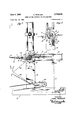
- Fig. 1 is a plan view of a machine illustrating the present invention, the upper portion thereof being broken away to more clearly illustrate the blades, the suction means, the gripping means and the gravity operable elements.
- Fig. 2 is a side view of the machine, partly in elevation and partly in section, substantially along the line 2-2 on Fig. 1.
- Fig. 3 is a fragmentary end view of the machine, as seen substantially along the line 3-3 on Fig. 2.
- Fig. 4 is a fragmentary side view of cam means for controlling the operation of the gripping means, as seen substantially along the line 44 on Fig. 3.
- Fig. 5 is a fragmentary, staggered sectional view taken along the line 55 on Fig. 3, illustrating valve means for controlling the operation of the suction means.
- Figs. 6 and 7 are sectional views taken respectively along the lines 6-6 and 7-7 on Fig. 3, illustrating the valve means in further detail.
- a sheet or web material folding machine which generally comprises a base or frame 10, a rotary unit or assembly supported by the base including web creasing blades 11, suction means 12, web gripping means 14, web discharging elements 15, cam means 16, valve means 17, and means 19 for accentuating the creases.
- the base or frame 10 comprises a pair of upright spaced-apart frame sections 20 between which the rotary unit is mounted, as described hereinafter, a pair of vertical rods 21 on each frame section 20, and a pair of horizontal rods 22 and 23 on each of the frame sections extending laterally therefrom at one side. 1
- web material W supplied by a roll (not shown) of such material passes around a pair of rolls 24 and 25 which cooperate with a tension bar 26, and then passes over an idler roll 27 supported by and between the rods 23.
- the means supporting the roll 27 are releasably attached to the rods 23 to adjust the position of this roll in a horizontal direction to position the same adjacent the path of the blade 11 for the purpose which will be made apparent hereinafter.
- the rotary uni-t is supported by and between the frame sections 20 in a manner to enable the blades to revolve counter-clockwise (as viewed in Fig. 2) and engage the underside of the web V! as it passes over the roll 27.
- This is accomplished by providing a disc member 30 (Fig. 4) inwardly disposed of one of the frame sections 2% and formed with a cylindrical portion 31 extending outwardly through and journalled in a bearing 32 in the frame section, and by providing a disc member 34 (Fig. 5) inwardly disposed of the other frame section 20 and carrying an axle or stub shaft 35 extending outwardly through and journalled for rotation in a bearing 36 in the last mentioned frame section.
- the outer end of the shaft 35 carries a drive pulley 37 adapted to be driven by a belt from a source of power (not shown). Also, a sprocket 39 is mounted and fixedly secured to this shaft for rotation therewith, the purpose of which will be described hereinafter, and a thrust bearing 5:0 is disposed between the sprocket and the frame section.
- the suction means 12 comprise an elongate rectangular casing 41 secured at its ends to the discs 3% and 3 to interconnect the discs for rotation. These casings are offset with respect to the axis of rotation of the discs, and are substantially diametrically opposite each other, as seen in Fig. 2, to provide a syr'nmetrical arrangement. 7
- Each ,of the casings 41 has a wide outer flat surface 42, furthest from the axis of rotation; and a wide inner surface 44 nearest to the axis of rotation (Fig. 2).
- the surface 42 has a row of apertures 45 along its edge nearest the axis of rotation for holding the web by suction against this surface when the casing is evacuated.
- valve means i? which comprise a port 46 in the disc 34 for each of the casings in communication therewith, a stationary valve body 47 having a pair of symmetrical circumferential recesses 4 and 5% with which the ports 46 are adapted to alternately register as the disc 34 rotates.
- the recess 49 is in communication with a conduit 51 (Figs. 5 and 6) connected to a vacuum pump (not shown), whereas the recess 5% is isolated from this conduit and, if desired, may be so arranged to provide an imperfect seal which permits atmosphericair. to leak therein; whereby the casings are alternately ren dered effective to hold the web and ineffective to release the web.
- the stationary valve body 47 has a central aperture 52 through which the shaft 35 extends and whereinthe shaft rotates.
- the valve body 47 is urged against the disc 34 by a plurality of compression springs 54 (Figs. and 6) mounted in recesses formed in the frame section 20 and is held against rotation with the shaft 35 by the conduit 51 or other suitable means for securing the same to the frame.
- the blades 11 each are secured to the casing surface 44 by bolts 55 (Fig. 2).
- the blades comprise two sections (Fig. l), thatis, an inner section 56 rigidly secured to the casing by the bolts 55 and an outer section 57 having a web creasing edge .59 parallel to the axis of rotation.
- the blade sections '56and 57 are adjustably secured to each other to vary the effective length thereof, or the distance the edge 59 .is located from the axis, by bolts 69 threaded 'into the section 56 and extending through slots 61 in the section 57.
- the gravity operable web discharging elements are each in the form of a generally U-shaped bail 64 hinged at its ends 65 to the side of the associated blade, which bail is in inverted position when the suction means cooperating therewith is rendered ineffective, whereby the bail tends to swing away from its associated blade to direct the web section engaged by it downwardly and away from the suction means, as will be described more fully hereinafter.
- the web gripping means 14 each comprise a presser bar 66 mounted on a shaft or rod 67 having its ends journalled for oscillating or pivotal movement in the discs 30 and 34 and adapted to revolve with these discs.
- These shafts are diametrically opposite each other, as seen in Fig. 2, and are arranged adjacent the side of the casings 41 having the apertures 45 therein for cooperation with the surfaces 42, acting as presser plates, to form a fold in the web.
- each shaft '67 extends outwardly through the disc portion 31 and has a lever 70 secured thereto.
- Each lever carries a revolvable roller 71 at the free end thereof adapted to engage a cam device 72, herein shown as a plunger 73 'slidably mounted in a casing 74 and having a projecting cam portion 75 yielda'b'ly urged into the path of the rollers 71 by a spring .76.
- This cam device is arranged to force the .lower presser bar 66, as seen in Fig. 2, against the suction casing surface 42 on which a fold is to be formed, while holding the upper presser bar away from its casing surface and against its associated blade, as is readily evident from Fig. 2. As shown in Fig. 4, this is accomplished by wrapping one end of a resilient link 77 at least partially about one of the shafts 67 in acounter-clockwise direction (as viewed) and fastening the same thereto, and similarly connecting the other end to the other shaft.
- a resilient link 77 at least partially about one of the shafts 67 in acounter-clockwise direction (as viewed) and fastening the same thereto, and similarly connecting the other end to the other shaft.
- the crease accentuatingmeans 19 comprises yieldable means, such as a rotatable brush 80 (Figs. 2 and 3) supported by trunnions 81 on the rods in the path of the blade edges 59.
- the trunnions 81 are releasably secured to the rods 20 to facilitate adjusting the vertical position of the brush withrespect to the axis of rotation of the rotary assembly for the purpose about to be made apparent.
- the machine is first adjusted to fold the web material into sections of a predetermined length. Assuming that all the sections are to have the same length, theblades 11 are adjusted to position the edges 59 thereof from the edge of the casing surfaces 42, where the apertures-45 are formed, the proper distance-to produce web sections of the desired length.
- the roll 27 is then adjusted .in a horizontal direction onthe 'rods'23,lso that the .ibladeedges59 clear the same but are closely adjacent thereto. If the crease produced by the blade edges is to be accentuated, the brush 80 is adjusted on the rods 20 so that the blade edge deflects the bristles thereof.
- the web material is positioned on the rolls 24, 25 and 27, across the blades 11, which are in horizontal position, and is folded under the blade at the left (as viewed in Fig. 2) and the lower presser bar 66 is caused to grip the leading edge portion of the web material and hold the same against the casing surface 42 which serves as a presser plate.
- the suction means are now made effective, whereby the leading portions of alternate'web sections A are held by suction against the casing surfaces 42 in contact therewith.
- the intermediate web section B is held in position across one of the blades 11, as shown, by reason of holding the web sections A as described.
- the valving for the suction means is so timed that the leading edgeof the section A is securely held against the surface 42 until the lower presser bar is actuated.
- the presser bar 66 exerts sufiicientforce against the presser plate surface 42 to form a permanent fold F.
- the angular shape of the presser bar lendsitself readily to forming a well defined fold, since the bend thereof registers with the corner of the casing 41 adjacent the openings 45, as is evident in the lower presser bar 66 of Fig. 2.
- such as a rubber band may be connected between the 1 free end thereof and the blade.
- the discharged web sections may :be collected and stacked at the lower portion of'the frame in'any suitable manner, but "preferably are placed on a conveyor belt 85; This belt may be moved very slowly, intermittently or onlyperiodically by drive means (not shown) driven by'the sprocket 39.
- All the web sections need not be of equal length but can be so formed that only alternate sections are of equal :len'gths. This is accomplished by adjusting-one of the blades to'producea section of given length and by adjusting the other blade to produce a section of a different length.
- the bristles of the brush 80 are sufliciently long to engage the blade edges when in slightly different positions with respect to the axis of rotation of the rotary assembly. 7
- the present invention provides a simple, practical, economical and efficient machine for creasing and/or folding web material and arranging the same in zig-zag relationship.
- rotary means rotatable about a single axis in a predetermined direction, a radially extending blade attached to said rotary means having an edge parallel to the axis of rotation of said rotary means for engaging a web; suction means carried by said rotary means for holding the web thereon located parallel to and adjacent the axis of rotation of said rotary means, gripping means carried by said rotary means for said web holding means coacting therewith to press a crosswise fold in the web, and means for actuating the gripping means in timed relation to rotation of the rotary means, said actuating means operating said gripping means once during a complete revolution of said rotary means,
- a web folding machine of the class described the combination of rotary means, a pair of diametrically opposite blades attached to said rotary means each having an edge parallel to the axis of rotation of said rotary means for engaging a web and folding a crosswise crease therein; a pair of substantially diametrically opposite suction means carried by said rotary means for holding the web thereon located parallel to and adjacent the a is of rotation of said rotary means, gripping means carried by said rotary means for each of said suction means coacting therewith to press a crosswise fold in the web parallel to the crease extending in the opposite direction in which the web is folded in forming the crease, whereby the web is folded in zig-zag relation, and means for actuating the gripping means in timed relation to rotation of the rotary means, said actuating means operating each of said gripping means once during a complete revolution of said rotary means.
- yieldable means are positioned in the path of said blade edges for accentuating the crease.
- a machine wherein mounting means are provided for varying the position of said yieldable means with respect to the axis of rotation of said rotary means.
- a machine according to claim 4, wherein said yieldable means is a rotatable brush.
- suction means include a fiat surface formed with apertures, for engaging the web and serving as a bed plate for coacting with said gripping means in the pressing of the fold into the web.
- said gripping means include a presser plate cooperating with said bed plate.
- valve means are provided for cyclically rendering said suction means effective to hold the web and for rendering said suction means ineffective to release the web in timed relation with said actuating means.
- said gripping means comprises a pivotally mounted shaft carried by said rotary means, a presser plate secured to said shaft and lever means secured to said shaft for rocking the same to cause said presser plate to form the fold in the web.
- a web folding machine of the class described the combination of rotary means, a pair of diametrically opposite blades attached to said rotary means each having an edge parallel to the axis of rotation of said rotary means for engaging a web and folding a crosswise crease therein; a pair of substantially diametrically opposite suction means carried by said rotary means for holding the web thereon located parallel to and adjacent the axis of rotation of said rotary means, gripping means carried by said rotary means for each of said suction means coacting therewith to press a crosswise fold in the web parallel to the crease extending in the opposite direction in which the web is folded in forming the crease, whereby the web is folded in Zig-zag relation, said gripping means comprising a pivotally mounted shaft carried by said rotary means, a presser plate secured to said shaft, lever means secured to said shaft for rocking the same to cause said presser plate to form a fold in the web, a roller carried by said lever, and cam means adjacent said rotary means for engaging said roller
- a machine according to claim 14 wherein means are provided for moving one of said levers to rock its shaft in a rotative direction opposite to the direction in which said rotary means are rotated to cause its presser plate to move toward its suction means, whereby said shaft interconnecting means is effective to rock said other of said shafts in the same rotative direction as said rotary means are rotated to cause its presser plate to move away from its suction means.
- said interconnecting means is a resilient link extending at least partially about one of said shafts in one direction and about said other of said shafts in an opposite direction and having its ends respectively secured to said shafts.
- a base having spaced upright side frames and spaced laterally extending members, rotary means supported between said frames, 21 pair of diametrically opposite blades carried by said rotary means each having a web creasing edge parallel to the axis of rotation of said rotary means, suction means adjacent each of said blades and parallel to and adjacent the axis of rotation of said rotary means, gripping means for each of said suction means carried by said rotary means co acting with said suction means for folding the web, each pair of said suction and gripping means being respectively spaced diametrically opposite the other pair of said suction and gripping means, means for alternately operating said gripping means in timed relation with said blades, a web guiding roll supported between said members adjacent the path of said edges, and means for holding the web under tension while passing over said roll. 1 a a 18.
- said blades are constructed and arranged to vary the length thereof, and means are provided for adjusting the position of said roll on
- a web folding machine of the class described the combination of a base having spaced upright side frames, rotary means supported between said frames, a pair of diametrically opposite suction means attached to said rotary means, a radially extending web creasing blade secured at one side thereof to each of said suction means, a gravity operable element hinged to each of said blades at the side opposite to that secured to said suction means, means for rendering said suction means effective to hold the web when facing upwardly and for rendering said suction means inetfeetive to release .the web at a particular moment when facing downwardly, gripping means for each of said suction means carried by said rotary means coacting with said suction means for folding the web, means for operating said gripping means when its suction means faces downwardly to press a fold into the web and 'then release the web, and means beneath said rotary means for receiving and stacking the folded web, said gravity operable means upon release of the Web by said gripping means and by said suction means serving to direct the
- a web folding machine'of-the class described the combination of a base having two spaced upright side frames provided with aligned-bearings, .a member journalled for rotation in each of said bearings, drive means'for one of said members,'a pair of diametrically opposite casings interconnecting said members whereby thedriven member will drive said othermember, said casings having an apertured surface, means for evacuat ing said casings, a radially extending web creasing blade secured at one side to each of said casings, means for rendering said evacuating means elfective and ineffective 'to cause said casings to respectively hold and release the web, a gripping bar for veach of said casings pivotally mounted between said members and carried thereby, and means for operating said gripping bars-in timed relation with said blades to 'fold the. web against said apertured surface and to release the same.
- said evacuating means include valving opcratively associated with one of said members in timed relation with said are associated with said other member.
Landscapes
- Folding Of Thin Sheet-Like Materials, Special Discharging Devices, And Others (AREA)
Description
June 4,1957 7 E. MUELLER 2,794,635
SHEET OR WEB MATERIAL FOLDING MACHINE Filed Aug. 13, 1953 3 Sheets-Sheet 1 EMIL MUELLER June 4, 1957 E. MUELLER SHEET 0R WEB MATERIAL FOLDING MACHINE 3 She'ets-Sheet 2 Filed Aug. 13, 1953 l INVENTOR EMIL MUELLER BYa ATTORN 'June 4, 1957 E. MUELLER 2,794,635
SHEET 0R WEB MATERIAL FOLDING MACHINE Filed Aug. 13, 1953 3 Sheets-Sheet 3 MIN I INVENTQR EMIL MUELLER United States Patent SHEET OR WEB MATERIAL FGLDING MACHINE Emil Mueller, Clifton, N. .l.
Application August 13, 1953, Serial No. 374,917
22 Claims. (Ci. 2713-70) The present invention relates to sheet or web material folding machines and, more particularly, to such machines of the multiple revolving blade type for folding and stacking the material in zig-zag relation.
The present invention aims to provide a machine of the foregoing character which embodies a number of improvements including web creasing blades, means for accentuating the crease, suction means for holding the web, gripping means cooperating with the suction means for forming a fold in the web, means for controlling the operation of the gripping and suction means, gravity operable elements for directing the web away from the suction means, and an arrangement for assembling the suction means, the blades, the gripping means and the control means as a rotary unit.
Accordingly, an object of the present invention is to provide such a machine which is simple and practical in construction.
Another object is to provide such a machine which is adapted for continuous operation for long periods without servicing.
Afurther object is to provide such a machine which is adjustable to produce folded web sections of various desired uniform lengths or alternative sections of different predetermined lengths.
A still further object is to provide such a machine which is adapted to fold pre-scored web material along the score lines in an accurate and reliable manner.
Other and further objects will be obvious upon an understanding of the illustrative embodiment about to be described, or will be indicated in the appended claims, and various advantages not referred to herein will occur to one skilled in the art upon employment of the invention in practice.
A preferred embodiment of the invention has been chosen for purposes of illustration and description and is shown in the accompanying drawing, forming a part of the specification, wherein: V
Fig. 1 is a plan view of a machine illustrating the present invention, the upper portion thereof being broken away to more clearly illustrate the blades, the suction means, the gripping means and the gravity operable elements.
Fig. 2 is a side view of the machine, partly in elevation and partly in section, substantially along the line 2-2 on Fig. 1.
Fig. 3 is a fragmentary end view of the machine, as seen substantially along the line 3-3 on Fig. 2.
Fig. 4 is a fragmentary side view of cam means for controlling the operation of the gripping means, as seen substantially along the line 44 on Fig. 3.
Fig. 5 is a fragmentary, staggered sectional view taken along the line 55 on Fig. 3, illustrating valve means for controlling the operation of the suction means.
Figs. 6 and 7 are sectional views taken respectively along the lines 6-6 and 7-7 on Fig. 3, illustrating the valve means in further detail.
Referring to the drawings in detail, there is shown a sheet or web material folding machine which generally comprises a base or frame 10, a rotary unit or assembly supported by the base including web creasing blades 11, suction means 12, web gripping means 14, web discharging elements 15, cam means 16, valve means 17, and means 19 for accentuating the creases.
The base or frame 10 comprises a pair of upright spaced-apart frame sections 20 between which the rotary unit is mounted, as described hereinafter, a pair of vertical rods 21 on each frame section 20, and a pair of horizontal rods 22 and 23 on each of the frame sections extending laterally therefrom at one side. 1
As shown in Fig. 2, web material W supplied by a roll (not shown) of such material, passes around a pair of rolls 24 and 25 which cooperate with a tension bar 26, and then passes over an idler roll 27 supported by and between the rods 23. The means supporting the roll 27 are releasably attached to the rods 23 to adjust the position of this roll in a horizontal direction to position the same adjacent the path of the blade 11 for the purpose which will be made apparent hereinafter.
As showin in Figs. 1, 2, 4 and 5, the rotary uni-t is supported by and between the frame sections 20 in a manner to enable the blades to revolve counter-clockwise (as viewed in Fig. 2) and engage the underside of the web V! as it passes over the roll 27. This is accomplished by providing a disc member 30 (Fig. 4) inwardly disposed of one of the frame sections 2% and formed with a cylindrical portion 31 extending outwardly through and journalled in a bearing 32 in the frame section, and by providing a disc member 34 (Fig. 5) inwardly disposed of the other frame section 20 and carrying an axle or stub shaft 35 extending outwardly through and journalled for rotation in a bearing 36 in the last mentioned frame section.
The outer end of the shaft 35 carries a drive pulley 37 adapted to be driven by a belt from a source of power (not shown). Also, a sprocket 39 is mounted and fixedly secured to this shaft for rotation therewith, the purpose of which will be described hereinafter, and a thrust bearing 5:0 is disposed between the sprocket and the frame section. When the pulley 37 is driven, the disc 34 is rotated and drives the disc 30 in the manner about to be described.
As shown in Figs. 1, 2 and 5, the suction means 12 comprise an elongate rectangular casing 41 secured at its ends to the discs 3% and 3 to interconnect the discs for rotation. These casings are offset with respect to the axis of rotation of the discs, and are substantially diametrically opposite each other, as seen in Fig. 2, to provide a syr'nmetrical arrangement. 7
Each ,of the casings 41 has a wide outer flat surface 42, furthest from the axis of rotation; and a wide inner surface 44 nearest to the axis of rotation (Fig. 2). The surface 42 has a row of apertures 45 along its edge nearest the axis of rotation for holding the web by suction against this surface when the casing is evacuated.
As shown in Figs. 5, 6 and 7, evacuation of the casings 41 is controll d by the valve means i? which comprise a port 46 in the disc 34 for each of the casings in communication therewith, a stationary valve body 47 having a pair of symmetrical circumferential recesses 4 and 5% with which the ports 46 are adapted to alternately register as the disc 34 rotates. The recess 49 is in communication with a conduit 51 (Figs. 5 and 6) connected to a vacuum pump (not shown), whereas the recess 5% is isolated from this conduit and, if desired, may be so arranged to provide an imperfect seal which permits atmosphericair. to leak therein; whereby the casings are alternately ren dered effective to hold the web and ineffective to release the web.
The stationary valve body 47 has a central aperture 52 through which the shaft 35 extends and whereinthe shaft rotates. The valve body 47 is urged against the disc 34 by a plurality of compression springs 54 (Figs. and 6) mounted in recesses formed in the frame section 20 and is held against rotation with the shaft 35 by the conduit 51 or other suitable means for securing the same to the frame.
As shown in Figs. '1, 2 and 5, the blades 11 each are secured to the casing surface 44 by bolts 55 (Fig. 2). Preferably, the blades comprise two sections (Fig. l), thatis, an inner section 56 rigidly secured to the casing by the bolts 55 and an outer section 57 having a web creasing edge .59 parallel to the axis of rotation. The blade sections '56and 57 are adjustably secured to each other to vary the effective length thereof, or the distance the edge 59 .is located from the axis, by bolts 69 threaded 'into the section 56 and extending through slots 61 in the section 57.
The gravity operable web discharging elements are each in the form of a generally U-shaped bail 64 hinged at its ends 65 to the side of the associated blade, which bail is in inverted position when the suction means cooperating therewith is rendered ineffective, whereby the bail tends to swing away from its associated blade to direct the web section engaged by it downwardly and away from the suction means, as will be described more fully hereinafter.
As shown in Figs. 1 to 5, the web gripping means 14 each comprise a presser bar 66 mounted on a shaft or rod 67 having its ends journalled for oscillating or pivotal movement in the discs 30 and 34 and adapted to revolve with these discs. These shafts are diametrically opposite each other, as seen in Fig. 2, and are arranged adjacent the side of the casings 41 having the apertures 45 therein for cooperation with the surfaces 42, acting as presser plates, to form a fold in the web.
In Figs. 1 to 4the mechanism 16 for rocking the shafts 67 to cause the bars 66 to press and release the folds in the web is illustrated. This mechanism comprises asymmetrical arrangement wherein each shaft '67 extends outwardly through the disc portion 31 and has a lever 70 secured thereto. Each lever carries a revolvable roller 71 at the free end thereof adapted to engage a cam device 72, herein shown as a plunger 73 'slidably mounted in a casing 74 and having a projecting cam portion 75 yielda'b'ly urged into the path of the rollers 71 by a spring .76.
This cam device is arranged to force the .lower presser bar 66, as seen in Fig. 2, against the suction casing surface 42 on which a fold is to be formed, while holding the upper presser bar away from its casing surface and against its associated blade, as is readily evident from Fig. 2. As shown in Fig. 4, this is accomplished by wrapping one end of a resilient link 77 at least partially about one of the shafts 67 in acounter-clockwise direction (as viewed) and fastening the same thereto, and similarly connecting the other end to the other shaft. Thus, when the lower shaft 67 is rocked in a counter-clockwise direction, the upper shaft is rocked in a clockwise direction.
The crease accentuatingmeans 19 comprises yieldable means, such as a rotatable brush 80 (Figs. 2 and 3) supported by trunnions 81 on the rods in the path of the blade edges 59. The trunnions 81 are releasably secured to the rods 20 to facilitate adjusting the vertical position of the brush withrespect to the axis of rotation of the rotary assembly for the purpose about to be made apparent.
In operation, the machine is first adjusted to fold the web material into sections of a predetermined length. Assuming that all the sections are to have the same length, theblades 11 are adjusted to position the edges 59 thereof from the edge of the casing surfaces 42, where the apertures-45 are formed, the proper distance-to produce web sections of the desired length.
The roll 27 is then adjusted .in a horizontal direction onthe 'rods'23,lso that the .ibladeedges59 clear the same but are closely adjacent thereto. If the crease produced by the blade edges is to be accentuated, the brush 80 is adjusted on the rods 20 so that the blade edge deflects the bristles thereof.
With the machine so adjusted, the web material is positioned on the rolls 24, 25 and 27, across the blades 11, which are in horizontal position, and is folded under the blade at the left (as viewed in Fig. 2) and the lower presser bar 66 is caused to grip the leading edge portion of the web material and hold the same against the casing surface 42 which serves as a presser plate. The suction means are now made effective, whereby the leading portions of alternate'web sections A are held by suction against the casing surfaces 42 in contact therewith. The intermediate web section B is held in position across one of the blades 11, as shown, by reason of holding the web sections A as described.
The drive is then causedto rotate the rotary assembly in a counter-clockwisedirection (Fig. 2). 'As the blade at the right is swung'upwardly, a crease C is formed therein, and this crease is accentuated by the brush 80 when the'blade edge carrying the web material passes through the bristle zone thereof. Assuming that the assembly has been rotated about 180, the section A first above the blade at the right is now below the bladeat the left, another section A is above the blade at the right, and an intermediate section B is above the lblade -at the left. -As the rotary assembly approaches this position, the cam device 72 causes the lower presser bar 66 to .engage the trailing portion of the section B and fold it under the leading edge of the adjacent section A. Preferably,
. the valving for the suction means is so timed that the leading edgeof the section A is securely held against the surface 42 until the lower presser bar is actuated. As the roller 71 engages the cam portion to fully rock the. shaft'67 in a clockwise directionto the position shown in Fig. 2, the presser bar 66 exerts sufiicientforce against the presser plate surface 42 to form a permanent fold F. It is to be noted that the angular shape of the presser bar, lendsitself readily to forming a well defined fold, since the bend thereof registers with the corner of the casing 41 adjacent the openings 45, as is evident in the lower presser bar 66 of Fig. 2. When the lower presser bar is so actuated, the upper presser bar is rocked in a counterclockwise direction (.as viewed in Fig. 2) through the resilient link 77 into connecting the shafts 67 and is held out of contact'with the web section B extending across the blade at the left.
After the roller 71 passes over the cam portion 75 and is released, the lower shaft 67 is rocked in a-counterclockwise direction, by virtue of the tension in resilient link 77, and disengages itself from the fold F. At this point, the vacuum in the casing 41 has been rendered ineffective and the leading portion of the section A at the apertures 45 is released. The weight of the bail 64 under the blade at the left, acted upon by gravity, causes this bail to swing downwardly clockwise, whereby the sections A and B, connected .by the fold F, are'directed downwardly. Continued operation of the machine causes alternate creases and folds to be formed in the web and web sections arrange in zig-zag relationship. In order to retract the bail quickly, a resilient element (not shown"),
such as a rubber band,.may be connected between the 1 free end thereof and the blade.
The discharged web sections may :be collected and stacked at the lower portion of'the frame in'any suitable manner, but "preferably are placed on a conveyor belt 85; This belt may be moved very slowly, intermittently or onlyperiodically by drive means (not shown) driven by'the sprocket 39.
All the web sections need not be of equal length but can be so formed that only alternate sections are of equal :len'gths. This is accomplished by adjusting-one of the blades to'producea section of given length and by adjusting the other blade to produce a section of a different length. The bristles of the brush 80 are sufliciently long to engage the blade edges when in slightly different positions with respect to the axis of rotation of the rotary assembly. 7
From the foregoing description, it will be seen that the present invention provides a simple, practical, economical and efficient machine for creasing and/or folding web material and arranging the same in zig-zag relationship.
As various changes may be made in the form, construction and arrangement of the parts herein, without departing from the spirit and scope of the invention and without sacrificing any of its advantages, it is to be understood that all matters are to be interpreted as illustrative and not in any limiting sense.
What is claimed is:
1. In a web folding machine of the class described, the combination of rotary means rotatable about a single axis in a predetermined direction, a radially extending blade attached to said rotary means having an edge parallel to the axis of rotation of said rotary means for engaging a web; suction means carried by said rotary means for holding the web thereon located parallel to and adjacent the axis of rotation of said rotary means, gripping means carried by said rotary means for said web holding means coacting therewith to press a crosswise fold in the web, and means for actuating the gripping means in timed relation to rotation of the rotary means, said actuating means operating said gripping means once during a complete revolution of said rotary means,
2. In a web folding machine of the class described, the combination of rotary means, a pair of diametrically opposite blades attached to said rotary means each having an edge parallel to the axis of rotation of said rotary means for engaging a web and folding a crosswise crease therein; a pair of substantially diametrically opposite suction means carried by said rotary means for holding the web thereon located parallel to and adjacent the a is of rotation of said rotary means, gripping means carried by said rotary means for each of said suction means coacting therewith to press a crosswise fold in the web parallel to the crease extending in the opposite direction in which the web is folded in forming the crease, whereby the web is folded in zig-zag relation, and means for actuating the gripping means in timed relation to rotation of the rotary means, said actuating means operating each of said gripping means once during a complete revolution of said rotary means.
3. A machine according to claim 2, wherein said blades comprise two sections adjustably secured together for varying the distance between said edge and the axis of rotation of said rotary means.
4. A machine according to claim 2, wherein yieldable means are positioned in the path of said blade edges for accentuating the crease.
5. A machine according to claim 4, wherein mounting means are provided for varying the position of said yieldable means with respect to the axis of rotation of said rotary means.
6. A machine according to claim 4, wherein said yieldable means is a rotatable brush.
7. A machine according to claim 2, wherein said suction means include a fiat surface formed with apertures, for engaging the web and serving as a bed plate for coacting with said gripping means in the pressing of the fold into the web.
8. A machine according to claim 7, wherein said gripping means include a presser plate cooperating with said bed plate.
9. A machine according to claim 2, wherein valve means are provided for cyclically rendering said suction means effective to hold the web and for rendering said suction means ineffective to release the web in timed relation with said actuating means.
l0. A machine according to claim 9, wherein said blades each have a hinged element thereon operable by gravity to direct the web away from the suction means upon the release of the web therefrom. I
11. A machine according to claim 2, wherein said gripping means comprises a pivotally mounted shaft carried by said rotary means, a presser plate secured to said shaft and lever means secured to said shaft for rocking the same to cause said presser plate to form the fold in the web.
12. In a web folding machine of the class described, the combination of rotary means, a pair of diametrically opposite blades attached to said rotary means each having an edge parallel to the axis of rotation of said rotary means for engaging a web and folding a crosswise crease therein; a pair of substantially diametrically opposite suction means carried by said rotary means for holding the web thereon located parallel to and adjacent the axis of rotation of said rotary means, gripping means carried by said rotary means for each of said suction means coacting therewith to press a crosswise fold in the web parallel to the crease extending in the opposite direction in which the web is folded in forming the crease, whereby the web is folded in Zig-zag relation, said gripping means comprising a pivotally mounted shaft carried by said rotary means, a presser plate secured to said shaft, lever means secured to said shaft for rocking the same to cause said presser plate to form a fold in the web, a roller carried by said lever, and cam means adjacent said rotary means for engaging said roller and operating said lever means to rock said shaft.
13. A machine according to claim 12, wherein said lever carries a roller and cam means in said actuating means are provided adjacent said rotary means for engaging said roller and operating said lever means to rock said shaft, said cam means comprising a yieldable element cam means is a yieldable element.
14. A machine according to claim 11, wherein means interconnect said shafts constructed and arranged to rock said one of said shafts in a rotative direction opposite to the rotative direction in which the said other of said shafts is rocked.
15. A machine according to claim 14, wherein means are provided for moving one of said levers to rock its shaft in a rotative direction opposite to the direction in which said rotary means are rotated to cause its presser plate to move toward its suction means, whereby said shaft interconnecting means is effective to rock said other of said shafts in the same rotative direction as said rotary means are rotated to cause its presser plate to move away from its suction means.
16. A machine according to claim 15, wherein said interconnecting means is a resilient link extending at least partially about one of said shafts in one direction and about said other of said shafts in an opposite direction and having its ends respectively secured to said shafts.
17. In a web folding machine of the class described, the combination of a base having spaced upright side frames and spaced laterally extending members, rotary means supported between said frames, 21 pair of diametrically opposite blades carried by said rotary means each having a web creasing edge parallel to the axis of rotation of said rotary means, suction means adjacent each of said blades and parallel to and adjacent the axis of rotation of said rotary means, gripping means for each of said suction means carried by said rotary means co acting with said suction means for folding the web, each pair of said suction and gripping means being respectively spaced diametrically opposite the other pair of said suction and gripping means, means for alternately operating said gripping means in timed relation with said blades, a web guiding roll supported between said members adjacent the path of said edges, and means for holding the web under tension while passing over said roll. 1 a a 18. A machine according to claim 17, wherein said blades are constructed and arranged to vary the length thereof, and means are provided for adjusting the position of said roll on said members.
19. A machine according to claim 18, wherein a brush roll is supported between said frames above said rotary means in the path of said edges, and means are provided for adjusting the position of said brush roll on said frames.
'20. In a web folding machine of the class described, the combination of a base having spaced upright side frames, rotary means supported between said frames, a pair of diametrically opposite suction means attached to said rotary means, a radially extending web creasing blade secured at one side thereof to each of said suction means, a gravity operable element hinged to each of said blades at the side opposite to that secured to said suction means, means for rendering said suction means effective to hold the web when facing upwardly and for rendering said suction means inetfeetive to release .the web at a particular moment when facing downwardly, gripping means for each of said suction means carried by said rotary means coacting with said suction means for folding the web, means for operating said gripping means when its suction means faces downwardly to press a fold into the web and 'then release the web, and means beneath said rotary means for receiving and stacking the folded web, said gravity operable means upon release of the Web by said gripping means and by said suction means serving to direct the folded web toward said last mentioned means.
21; In ,a web folding machine'of-the class described, the combination of a base having two spaced upright side frames provided with aligned-bearings, .a member journalled for rotation in each of said bearings, drive means'for one of said members,'a pair of diametrically opposite casings interconnecting said members whereby thedriven member will drive said othermember, said casings having an apertured surface, means for evacuat ing said casings, a radially extending web creasing blade secured at one side to each of said casings, means for rendering said evacuating means elfective and ineffective 'to cause said casings to respectively hold and release the web, a gripping bar for veach of said casings pivotally mounted between said members and carried thereby, and means for operating said gripping bars-in timed relation with said blades to 'fold the. web against said apertured surface and to release the same.
22. A machine according to claim 21, wherein said evacuating means include valving opcratively associated with one of said members in timed relation with said are associated with said other member.
operating means, and said gripping bar operating means References Cited in the file of this patent UNITED STATES PATENTS 217,071 Crowell July 1, 1879 1,186,018 'Meisel June 6, 1916 2,092,952 Campbell Sept. 14, 1937 FOREIGN PATENTS 362,121 Great Britain Dec. 3, 1931
Priority Applications (1)
| Application Number | Priority Date | Filing Date | Title |
|---|---|---|---|
| US374017A US2794635A (en) | 1953-08-13 | 1953-08-13 | Sheet or web material folding machine |
Applications Claiming Priority (1)
| Application Number | Priority Date | Filing Date | Title |
|---|---|---|---|
| US374017A US2794635A (en) | 1953-08-13 | 1953-08-13 | Sheet or web material folding machine |
Publications (1)
| Publication Number | Publication Date |
|---|---|
| US2794635A true US2794635A (en) | 1957-06-04 |
Family
ID=23474888
Family Applications (1)
| Application Number | Title | Priority Date | Filing Date |
|---|---|---|---|
| US374017A Expired - Lifetime US2794635A (en) | 1953-08-13 | 1953-08-13 | Sheet or web material folding machine |
Country Status (1)
| Country | Link |
|---|---|
| US (1) | US2794635A (en) |
Citations (4)
| Publication number | Priority date | Publication date | Assignee | Title |
|---|---|---|---|---|
| US217071A (en) * | 1879-07-01 | Improvement in sheet-delivery apparatus for printing-machines | ||
| US1186018A (en) * | 1915-11-01 | 1916-06-06 | Meisel Press And Mfg Company | Folding-machine. |
| GB362121A (en) * | 1930-11-08 | 1931-12-03 | R J Ederer Company | Improvements relating to the conveying and piling of nets, fabrics and similar materials |
| US2092952A (en) * | 1934-11-26 | 1937-09-14 | Samuel J Campbell | Paper interfolding machine |
-
1953
- 1953-08-13 US US374017A patent/US2794635A/en not_active Expired - Lifetime
Patent Citations (4)
| Publication number | Priority date | Publication date | Assignee | Title |
|---|---|---|---|---|
| US217071A (en) * | 1879-07-01 | Improvement in sheet-delivery apparatus for printing-machines | ||
| US1186018A (en) * | 1915-11-01 | 1916-06-06 | Meisel Press And Mfg Company | Folding-machine. |
| GB362121A (en) * | 1930-11-08 | 1931-12-03 | R J Ederer Company | Improvements relating to the conveying and piling of nets, fabrics and similar materials |
| US2092952A (en) * | 1934-11-26 | 1937-09-14 | Samuel J Campbell | Paper interfolding machine |
Similar Documents
| Publication | Publication Date | Title |
|---|---|---|
| US5000729A (en) | Bag folding machine | |
| US3632104A (en) | Balanced folder assembly | |
| US3034409A (en) | Method and apparatus for producing and applying bag handles | |
| GB529344A (en) | Improvements in or relating to sheet conveyor mechanism | |
| US3363896A (en) | Methods and apparatus for zig-zag folding a web | |
| US2794635A (en) | Sheet or web material folding machine | |
| US4210318A (en) | Fan folding and stacking device | |
| US1595992A (en) | Interfolding machine | |
| US3217646A (en) | Mechanism for removing dusting powder or loose particles from sheets or webs | |
| US2738842A (en) | Web cutting apparatus for printing machines and the like | |
| US2612088A (en) | Closure flap folding and envelope stacking mechanism for envelope machines | |
| US2086138A (en) | Paper feeding device | |
| US1962128A (en) | Sheet cutting and printing machine | |
| US1999836A (en) | Feeding mechanism | |
| US4010598A (en) | Device for folding the closure flap of envelopes | |
| US4290764A (en) | Method and apparatus for folding a cardboard sheet along a straight fold line | |
| US229419A (en) | jones | |
| SU442948A1 (en) | Rotational folder | |
| US1993240A (en) | Pneumatic feeder | |
| US1924754A (en) | Rotary folder for paper-bag making and similar machines | |
| US1179002A (en) | Signature-handling machine. | |
| US2528159A (en) | Rotary sheet folder | |
| GB2078088A (en) | Device for fitting filters to cigarettes | |
| US2673497A (en) | Machine for the manufacture of envelopes and flat bags with inside arranged folding seams | |
| US3456942A (en) | Transfer attachment for envelope forming machine |