US2788198A - Air conditioning apparatus - Google Patents
Air conditioning apparatus Download PDFInfo
- Publication number
- US2788198A US2788198A US312330A US31233052A US2788198A US 2788198 A US2788198 A US 2788198A US 312330 A US312330 A US 312330A US 31233052 A US31233052 A US 31233052A US 2788198 A US2788198 A US 2788198A
- Authority
- US
- United States
- Prior art keywords
- blower fan
- pump
- motor
- cable
- water
- Prior art date
- Legal status (The legal status is an assumption and is not a legal conclusion. Google has not performed a legal analysis and makes no representation as to the accuracy of the status listed.)
- Expired - Lifetime
Links
- 238000004378 air conditioning Methods 0.000 title description 16
- XLYOFNOQVPJJNP-UHFFFAOYSA-N water Substances O XLYOFNOQVPJJNP-UHFFFAOYSA-N 0.000 description 29
- 230000003134 recirculating effect Effects 0.000 description 25
- 230000008878 coupling Effects 0.000 description 15
- 238000010168 coupling process Methods 0.000 description 15
- 238000005859 coupling reaction Methods 0.000 description 15
- 238000004064 recycling Methods 0.000 description 9
- 230000001276 controlling effect Effects 0.000 description 7
- 238000010276 construction Methods 0.000 description 5
- 239000012809 cooling fluid Substances 0.000 description 4
- 230000003028 elevating effect Effects 0.000 description 4
- 239000012530 fluid Substances 0.000 description 3
- 239000000835 fiber Substances 0.000 description 2
- 238000001816 cooling Methods 0.000 description 1
- 239000000498 cooling water Substances 0.000 description 1
- 238000007599 discharging Methods 0.000 description 1
- 230000009977 dual effect Effects 0.000 description 1
- 230000001050 lubricating effect Effects 0.000 description 1
- 238000005461 lubrication Methods 0.000 description 1
- 230000004048 modification Effects 0.000 description 1
- 238000012986 modification Methods 0.000 description 1
- 230000001105 regulatory effect Effects 0.000 description 1
- 230000035939 shock Effects 0.000 description 1
- 125000006850 spacer group Chemical group 0.000 description 1
- 229910001220 stainless steel Inorganic materials 0.000 description 1
- 239000010935 stainless steel Substances 0.000 description 1
Images

Classifications
-
- F—MECHANICAL ENGINEERING; LIGHTING; HEATING; WEAPONS; BLASTING
- F24—HEATING; RANGES; VENTILATING
- F24F—AIR-CONDITIONING; AIR-HUMIDIFICATION; VENTILATION; USE OF AIR CURRENTS FOR SCREENING
- F24F6/00—Air-humidification, e.g. cooling by humidification
- F24F6/02—Air-humidification, e.g. cooling by humidification by evaporation of water in the air
- F24F6/04—Air-humidification, e.g. cooling by humidification by evaporation of water in the air using stationary unheated wet elements
Definitions
- One of the objects of my invention is to provide a humidity control attachment for blower fans which may be readily applied to conventional types of air circulating fans and the driving motor for the air circulating fan employed for operating the humidity control apparatus.
- Another object of my invention is to provide a construction of humidity control attachment for blower fans in which a coupling may be established from the operating motor of the blower fan to a water elevating pump for effecting a recirculation of water through filter pads associated with the blower fan for controlling conditions of humidity simultaneously with the operation of the blower fan.
- Another object of my invention is to provide an improved construction of recirculating pump which may be submerged in a drain pan adjacent the base of a blower fan and operated simultaneously with the operation of the blower fan for recirculating the water through filter pads associated with the blower fan for controlling conditions of humidity simultaneously with the operation of the blower fan.
- Still another object of my invention is to provide a construction of recirculating water pump which may be readily coupled through a flexible drive shaft with the driving motor of a blower fan, for recirculating water through lter pads associated with the blower fan simultaneously with the operation of the blower fan for continuously controlling humidity conditions as air is circulated by the blower fan.
- Still another object of my invention is to provide a construction of cable driven recirculating pump which may be driven by the same motor which drives the blower fan of an air conditioner, for recirculating cooling fluid through filter pads associated with the blower fan where the recirculating pump contains a volute scroll described according to an exponential curve for a pump, elevating and discharging a stream of cooling fluid with a very high degree of efiiciency.
- Still another object of my invention is a structural arrangement for mounting a ilexible cable coupling means with respect to the driving motor of a blower fan and with respect to a centrifugal pump supported on the casing of the blower fan and submerged in a water collecting tray beneath the fan, for recirculating a cooling fluid through filter pads associated with the blower fan.
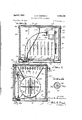
- Figure 1 is a vertical sectional view taken through an air conditioning unit substantially on line 1--1 of Fig. 2,
- FIG. 2 is a transverse vertical sectional view taken substantially on line 2-2 of Fig. l;
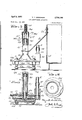
- Fig. 3 is a side elevational view of the recirculating pump with parts broken away and shown in section, and illustrating the manner of attachment with the blower fan casing;
- Fig. 4 is :a vertical sectional view through the recirculating pump taken substantially on line 4-4 of Fig. 6;
- Fig. 5 is a vertical sectional View through the recirculating pump taken substantially on line 5-5 of Figs. 6 and 7;
- Fig. 6 is a horizontal sectional view taken substantially on line 6-6 of Fig.
- Fig. 7 is a horizontal sectional view taken substantially on line 7-7 of Fig. 5 and illustrating the volute and the rotor therein and the coaction thereof, for whipping t the water centrifugally outwardly and upwardly through the flexible discharge leading from the recirculating pump to the distributing pipe at the top of the casing of the air conditioning unit;
- Fig. 8 is a bottom plan view of the casing;
- Fig. 9 is a top plan view of the rotor of the centrifugal pump showing the vanes beneath the rotor;
- Fig. l0 is a vertical sectional view through the rotor substantially on line 1 0-10 of Fig. 9; Fig.
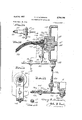
- Fig. 12 is a fragmentary sectional view showing more particularly the association of the motor shaft with the flexible driving cable leading to the recirculating pump and illustrating the mounting means therefor;
- Fig. 13 is a sectional view taken substantially on line 13-13 of Fig. l2, showing particularly the adjustable bracket for mounting the flexible cable coupling from the recirculating pump to the driving motor;
- Fig. 14 is a sectional View taken substantially on line 14-14 of Fig. 13;
- Fig. 15 is a transverse sectional view taken substantially on line 15-15 of Fig. 12;
- Fig. 16 is an elevational view of the coupling connection between the driving motor and the flexible cable leading to the recirculating pump.
- My invention is directed to an attachment for blower fans for providing a humidity control system in association with the blower fan, utilizing the same motor which operates the blower fan for controlling the operation of a centrifugally operated recirculating pump, which is adapted to elevate cooling fluid from a tray beneath the blower fan and filter pads associated therewith, for distribution through the top of the filter pads for producing by recycling operations, evaporative cooling.
- I provide means for very readily mounting a centrifugally operated water recirculating pump in a position submerged in the water collecting tray adjacent the base of the apparatus, with a iiexible drive shaft leading to the motor which drives the blower fan.
- the same motor which operates the blower fan also drives the centrifugally operated recirculating pump, thus obtaining dual use of the driving motor.
- reference character 1 designates a supporting tray located at the base of the air conditioning unit, and into which water is replenished from time to time to water level 2 in the tray 1.
- An automatic fluid valve may be provided for replenishing the water supply from time to time.
- I provide supporting angles 3 and 4, serving as' feet for mounting the frame of the blower fan, represented at SVandthrough which blower fan shaft 6 is Ajournalled for operating blower fan blade 7 from driven pulley tl on the end of shaft 6.
- the driven pulley e is operated by belt 9' extending fromd'riving pulley lil onmotor shaft lil driven ⁇ by -electric 'motoru12- .
- the electric motor l2 is mounted on brackets lll which are supported 'with respect to the frame 5 of the blower fan.
- the brackets '14 are illustrated more clearly in Figs. l2, 13 and 14, from which it will be notedthat motor l2 is Vsupported in a position projecting from one side of the frame of the blower fan, as shown more particularly in Fig. 2.
- the opposite end of shaft il of motor l2 is journalled in bearing 1S, as shown more particularly in Fig.
- vCoupling member i7 is of rectangular section, similar to the sectionof the key slot. i6.
- the coupling member i7 V projects outwardly and through the coupling sleeve 18, which is also of rectangular section.
- the coupling sleeve 18 projects outwardly from the end of the motor frame and into the cable ferrule i9.
- the cable ferrule i9 is apertured to receive the sleeve l at one end, as shown at 2li, and is apertured to receive the end of the flexible cable housing 2l in the other'end 22 thereof.
- a washer member 23 is interposed between the aperture Ztl in cable ferrule 19 and the end 22 of the cable ferrule i9.
- the flexible cable housing 2l Vis positively maintained in the end 22 of the cable ferrule i9.
- a dustrcap 2S is inserted over the sleeve 1S, and is centered within the recess 26 in the end of the frame of the electric motor represented at 12a.
- the position of the cable ferrule i9 with respect to the end of the motor frame, is adjusted by means of the external screw threads 19a on the exterior surface of the cable ferrule 19, which screw threads are engaged by the adjustable locknuts 27 and 28 on opposite sides of the adjustable bracket member 29.
- the adjustable bracket member 29 is apertured at 29a for the passage of the cable ferrule i9, so that the cable ferrulc 19 is gripped within the aperture 29a by the adjustable locknuts 27 and Z.
- the bracket member 29 forms parts of the universal adapter bracket for holding the upper end of the llexible cable assembly in cable housing 2l in position with relation to the blower motor l2. Bracket member 29 coacts with the angle member 3l), which is adjustably fastened to one of the brackets le which supports the blower motor. r.the universal adjustment provided by the adapter bracket is accomplished by the coaction of the slot 29h in bracket member 29 and fastening bolt 3l with the angle member 30, whereby bracket member 29 is linearly adjustable toward or away from the motor mounting means on brackets 14 for exactly aligning the cable ferrule i9 with the sleeve i8.
- the angle member 3d is provided with a multiplicity of spaced apertures 3tlg, Stirb and 39e therein, through which adjustable bolt member 33 extends and is engaged in elongated slot 32a in strip 32.
- the angle member 3i) is longitudinally adjustable along the strip 32 in spatial relation to the end of the frame of the electric motor l2 to present bracket member 29 to a selected position along cable ferrule il?, thereby precisely controlling the position of the end of the flexible cable with respect to the end of the motor shaft l1.
- the flexible cable housing 2l housing the cable core 24, extends through the air conditioning unit around the frame S of the blower fan, and extends through the cable ferrule 34 which is secured by the cable coupling sleeve 3S to the screw-threaded endof thecylindrical coupling 36.
- the cylindrical coupling 36 engages over the upwardly extending end 3'7 of the centrifugal pump housing 33.
- the upwardly extending end 37 is internally recessed at 37a for receiving the laminated fiber bearings represented at 39.
- a keeper key 40 engaged in a groove on the vertically extending impeller shaft 4l, retains the laminated liber bearings 39 in position.
- the cylindrical coupling 3o is apertured in the sides thereof, as represented at 3dr; and 36h, for facilitating the lubrication of the laminated fiber bearings 39.
- the upper end of the impeller shaft Si tits into the cable tip 42 carried by the end of the cable core 24, whereby the rotary driving torque imparted by cable core 21lis'transferred to the impeller shaft 4l.
- impeller shaft 4l extends downwardly through the upwardly extending end 37 of the pump housing 38, and passes through the laminated liber bearings 43 adjacent the lower end'of impeller shaft 41.
- lmpeller shaft il ⁇ then extends through the stainless steel spacer Lift, and is secured to the impeller 4S.
- the im peller 45 is mounted within the casing 46 of the pump, which connects with the pump housing 38 by means of bolt members 47, passing through aligned ilanges 38a and toa and through lthe'gasket 48, forming a fluidtight centrifugal pump casing.
- the bolt members 47 clamp the casing do to the pump housing 3% by means of securing nuts 47a, and in addition these bolt members support resilient feet 4715 which serve to contact the bottom surface of the supporting tray l and elevate the centrifugal pump sufficiently above the bottom'of supporting tray l to enable the water in the tray to be forced under vacuum pressure through the central intake aperture 5l and through the centrifugal pump to the Water distribution system.
- These resilient feet 471'; ⁇ also absorb shock vibration which may be communicated to the centrifugal pump housing through the rotatively driven ilexible shaft.
- rIhe centrifugal pump casing has a depending cylindrical portion 49 thereon, which serves as a support on the lower end thereof for the strainer or screen Sil.
- the depending cylindrical portion i9 constitutes the intake for the centrifugal pump, having a central intake port 5l, through which the sleeve 45a of the impeller 45 extends.
- the annular space between the projecting end of impeller 45a and port 5l serves as an intake for the water from the supporting tray l which is acted upon by the impeller 45, driven by shaft fil, to whip the water into the volute scroll within casing 46, which I have described more clearly in Fig. 7.
- the centrifugal recycling pump is designed for operation in a submerged condition below the water level 2 in tray l, and the automatic replenishment of the walter to supporting tray 1 insures an adequate supply of water submerging the pump for recycling operation.
- the volute scroll is designed on an exponential curve, starting at a point a and continuing through 366 to the point a', as shown more particularly in Fig. 7.
- 45C, 45d and 45e tend to centrifugally whip the water upwardly through the portfSl and outwardly alongthe volute path of the volute scroll 52 to the bottom of the recess 53 which forms a pocket toward which the end of the discharge tube 54, which is mounted in the extension 55 of pump housing 38, is axially directed.
- the discharge tube 54 thus receives the water which is pumped by the centrifugal action of the impeller l5 and forced upwardly through discharge tube 45 and through coupling 56 to the flexible hose 57.
- the exible hose 57 connects at the top of the air conditioning unit to a water distribution system shown more particularly in Figs. l and 2.
- the water distribution system comprises a transversely extending manifold 58, to which the flexible hose 57 connects through coupling 59.
- the manifold 58 extends in opposite directions and connects with transversely extending distribution pipes 6i) and nl through pipes 62 and 63.
- Distribution pipes 60 and el provide drip apertures through which the water is permitted to drip into iilter pads arranged in the sides of the casing of the air conditioning unit, and represented at 64, 65, 66 and 67.
- the continuous supply of water to these filter pads enables moisture to be imparted to the air which is drawn through the side walls of the housing by the operation of the blower fan 7. As the water gravitates through the filter pads, it returns to the supporting tray l to the level Z below which the recirculating pump is submerged, and it performs a recycling operation as hereinbefore described.
- the amount of air delivered by the blower is controlled by the angularly movable louvers 68 located in the discharge duct 69 of the frame 5 of the blower fan, and controlled from the outside of the air conditioning unit by means of manual control 7i) for regulating the discharge of properly humidified air through the grill 7l.
- the intake for the blower fan 7 is through the frame of the blower fan and the slots which are provided on all four sides of the frame 5, as represented at 5a, 5b, 5c, etc.
- the path of air follows the course represented by the arrows in Figs. l and 2 through the filter pads located in the side walls of the frame of the air conditioning unit, which i have designated generally as 75.
- l provide a hold down bracket 72, as shown in Fig. 3, which is provided with a horizontally extending foot 73, which surrounds the pump housing 38, and is secured at the upper ⁇ end thereof by screw threaded bolts 7d to the frame 5 of the blower fan.
- Air conditioning apparatus comprising a frame structure, a fan housing, a blower fan iournaled within said fan housing, a supporting tray for fluid, a fluid distribution system adjacent the top of said frame structure, a recycling pump adiacent one end of said fan housing for elevating iiuid, from said supporting tray to said water distribution system, a driving motor located adjacent the other end of said fan housing, bracket -ineans attached to said fan housing for supporting said motor with the driving axis thereof extending parallel to the driven axis of said blower fan and mounted within the limits of said fan housing, means for driving said blower fan from one end of said motor, a flexible shaft extending longitudinally and externaly of said fan housing between said recycling pump and the other end of said motor and means for longitudinally adjusting the position of the end of said fietible shaft with respect to the last mentioned end of said motor for insuring the continuous positive operation of said recycling pump simultaneously with the operation of said blower fan.
- Air conditioning apparatus as set forth in claim l in which the means for longitudinally adjusting the position of said iiexible shaft with respect to the last mentioned end of said motor is supported from the bracket means which supports said motor.
- Air conditioning apparatus as set forth in claim l in which said means for longitudinally adjusting the position of the exible shaft with respect to the last mentioned end of said motor consists of a bracket member which slidably engages said bracket means at one end and supports a cable housing in the other end thereof, said cable housing engaging said flexible shaft for rotatably supporting the shaft while allowing axial adjust-ment thereof between the end of said motor and the said recycling pump.
Landscapes
- Engineering & Computer Science (AREA)
- Chemical & Material Sciences (AREA)
- Combustion & Propulsion (AREA)
- Mechanical Engineering (AREA)
- General Engineering & Computer Science (AREA)
- Structures Of Non-Positive Displacement Pumps (AREA)
Description
v. R. ANDERSON AIR conm April 9, 1957 TIONING APPARATUS 4 Sheets-Sheet l Filed Sept. 30.' 1952 :El .Iii-...l 7/ 5g INVENToR. f2/Mm 53. Mdm/ww,
April 9, 1957 v. R. ANDERSON 2,788,198
AIR CONDITIONING APPARATUS Filed Sept. 30, 1952 4 sheds-sheet 2 April 9, 1957 v. R. ANDERSON AIR CONDITIONING APPARATUS Filed Sept. 30, 1952 ETEF- 5 /g 4 Sheetsheet 3 6,4 ITQE 4' IN1/EN Tore. c
April 9, 1957 v. R. ANDERSON 2,788,198
AIR CONDITIONING APPARATUS Filed Sept. 30, 1952 :F1 all. E
4 Sheets-Sheet 4 /30 JNVENTo L 1| f MW @L @tmb/maw fr. 9 BY e 61ML 5 :Fira-.ILE dvi 'lq/VFY United States Patent O AIR CONDITIONNG APPARATUS Verne R. Anderson, Tucson, Ariz. Application September 30, 1952, Serial No. 312,330 3 Claims. (Cl. 26l-29) My invention relates broadly to air conditioning apparatus, and more particularly to a humidity control attachment for blower fans.
One of the objects of my invention is to provide a humidity control attachment for blower fans which may be readily applied to conventional types of air circulating fans and the driving motor for the air circulating fan employed for operating the humidity control apparatus.
Another object of my invention is to provide a construction of humidity control attachment for blower fans in which a coupling may be established from the operating motor of the blower fan to a water elevating pump for effecting a recirculation of water through filter pads associated with the blower fan for controlling conditions of humidity simultaneously with the operation of the blower fan.
Another object of my invention is to provide an improved construction of recirculating pump which may be submerged in a drain pan adjacent the base of a blower fan and operated simultaneously with the operation of the blower fan for recirculating the water through filter pads associated with the blower fan for controlling conditions of humidity simultaneously with the operation of the blower fan.
Still another object of my invention is to provide a construction of recirculating water pump which may be readily coupled through a flexible drive shaft with the driving motor of a blower fan, for recirculating water through lter pads associated with the blower fan simultaneously with the operation of the blower fan for continuously controlling humidity conditions as air is circulated by the blower fan.
Still another object of my invention is to provide a construction of cable driven recirculating pump which may be driven by the same motor which drives the blower fan of an air conditioner, for recirculating cooling fluid through filter pads associated with the blower fan where the recirculating pump contains a volute scroll described according to an exponential curve for a pump, elevating and discharging a stream of cooling fluid with a very high degree of efiiciency.
Still another object of my invention is a structural arrangement for mounting a ilexible cable coupling means with respect to the driving motor of a blower fan and with respect to a centrifugal pump supported on the casing of the blower fan and submerged in a water collecting tray beneath the fan, for recirculating a cooling fluid through filter pads associated with the blower fan.
Other and further objects of my invention reside in the construction of attachment means for the driving motor of a blower fan by which the driving motor also operates a water recirculating pump for controlling humidity conditions under which the blower fan operates, as set forth more fully in the specification hereinafter following by reference to the accompanying drawings, in which:
Figure 1 is a vertical sectional view taken through an air conditioning unit substantially on line 1--1 of Fig. 2,
and illustrating the driving motor which simultaneously -operates both the blower fan and the recirculating pump for controlling conditions of humidity; Fig. 2 is a transverse vertical sectional view taken substantially on line 2-2 of Fig. l; Fig. 3 is a side elevational view of the recirculating pump with parts broken away and shown in section, and illustrating the manner of attachment with the blower fan casing; Fig. 4 is :a vertical sectional view through the recirculating pump taken substantially on line 4-4 of Fig. 6; Fig. 5 is a vertical sectional View through the recirculating pump taken substantially on line 5-5 of Figs. 6 and 7; Fig. 6 is a horizontal sectional view taken substantially on line 6-6 of Fig. 5, and illustrating in plan the top of the recirculating pump; Fig. 7 is a horizontal sectional view taken substantially on line 7-7 of Fig. 5 and illustrating the volute and the rotor therein and the coaction thereof, for whipping t the water centrifugally outwardly and upwardly through the flexible discharge leading from the recirculating pump to the distributing pipe at the top of the casing of the air conditioning unit; Fig. 8 is a bottom plan view of the casing; Fig. 9 is a top plan view of the rotor of the centrifugal pump showing the vanes beneath the rotor; Fig. l0 is a vertical sectional view through the rotor substantially on line 1 0-10 of Fig. 9; Fig. l1 is a horizontal sectional view taken substantially on line 11-11 of Fig. 3 through the driving connection to the recirculating pump showing the openings for lubricating the pump; Fig. 12 is a fragmentary sectional view showing more particularly the association of the motor shaft with the flexible driving cable leading to the recirculating pump and illustrating the mounting means therefor; Fig. 13 is a sectional view taken substantially on line 13-13 of Fig. l2, showing particularly the adjustable bracket for mounting the flexible cable coupling from the recirculating pump to the driving motor; Fig. 14 is a sectional View taken substantially on line 14-14 of Fig. 13; Fig. 15 is a transverse sectional view taken substantially on line 15-15 of Fig. 12; and Fig. 16 is an elevational view of the coupling connection between the driving motor and the flexible cable leading to the recirculating pump.
My invention is directed to an attachment for blower fans for providing a humidity control system in association with the blower fan, utilizing the same motor which operates the blower fan for controlling the operation of a centrifugally operated recirculating pump, which is adapted to elevate cooling fluid from a tray beneath the blower fan and filter pads associated therewith, for distribution through the top of the filter pads for producing by recycling operations, evaporative cooling. I provide means for very readily mounting a centrifugally operated water recirculating pump in a position submerged in the water collecting tray adjacent the base of the apparatus, with a iiexible drive shaft leading to the motor which drives the blower fan. Thus, the same motor which operates the blower fan also drives the centrifugally operated recirculating pump, thus obtaining dual use of the driving motor. Considerable saving in the consumption of electric power may be obtained as the blower motor is also employed to operate the recirculating pump. Moreover, economies are effected in the operation of the centrifugally recirculating pump of my invention, as the cooling water may be used in the recycling operations with infrequent replenishments in the water supply.
Referring to the drawings in more detail, reference character 1 designates a supporting tray located at the base of the air conditioning unit, and into which water is replenished from time to time to water level 2 in the tray 1. An automatic fluid valve may be provided for replenishing the water supply from time to time. Within the tray 1, I provide supporting angles 3 and 4, serving as' feet for mounting the frame of the blower fan, represented at SVandthrough which blower fan shaft 6 is Ajournalled for operating blower fan blade 7 from driven pulley tl on the end of shaft 6. The driven pulley e is operated by belt 9' extending fromd'riving pulley lil onmotor shaft lil driven `by -electric 'motoru12- .The electric motor l2 is mounted on brackets lll which are supported 'with respect to the frame 5 of the blower fan. The brackets '14 are illustrated more clearly in Figs. l2, 13 and 14, from which it will be notedthat motor l2 is Vsupported in a position projecting from one side of the frame of the blower fan, as shown more particularly in Fig. 2. The opposite end of shaft il of motor l2 is journalled in bearing 1S, as shown more particularly in Fig. l2, and is recessed within the end of the electric motor l2, as represented at lZa. The end of the shaft il is provided with a key slot represented at lo, which is rectangular in section, into which the coupling member l' extends. vCoupling member i7 is of rectangular section, similar to the sectionof the key slot. i6. The coupling member i7 Vprojects outwardly and through the coupling sleeve 18, which is also of rectangular section. The coupling sleeve 18 projects outwardly from the end of the motor frame and into the cable ferrule i9. The cable ferrule i9 is apertured to receive the sleeve l at one end, as shown at 2li, and is apertured to receive the end of the flexible cable housing 2l in the other'end 22 thereof. A washer member 23 is interposed between the aperture Ztl in cable ferrule 19 and the end 22 of the cable ferrule i9. The flexible cable housing 2l Vis positively maintained in the end 22 of the cable ferrule i9. Through the cable housing 21 there extends the llexible cable core Z4, which extends through the end of the cable ferrule Z2 and through Washer member 23 and into the end of sleeve Ilia which is attached to the coupling member i7 connected with motor shaft ll. Thus, a positive driving connection is secured between motor shaft ll and cable core 24. A dustrcap 2S is inserted over the sleeve 1S, and is centered within the recess 26 in the end of the frame of the electric motor represented at 12a. The position of the cable ferrule i9 with respect to the end of the motor frame, is adjusted by means of the external screw threads 19a on the exterior surface of the cable ferrule 19, which screw threads are engaged by the adjustable locknuts 27 and 28 on opposite sides of the adjustable bracket member 29. The adjustable bracket member 29 is apertured at 29a for the passage of the cable ferrule i9, so that the cable ferrulc 19 is gripped within the aperture 29a by the adjustable locknuts 27 and Z. The bracket member 29 forms parts of the universal adapter bracket for holding the upper end of the llexible cable assembly in cable housing 2l in position with relation to the blower motor l2. Bracket member 29 coacts with the angle member 3l), which is adjustably fastened to one of the brackets le which supports the blower motor. r.the universal adjustment provided by the adapter bracket is accomplished by the coaction of the slot 29h in bracket member 29 and fastening bolt 3l with the angle member 30, whereby bracket member 29 is linearly adjustable toward or away from the motor mounting means on brackets 14 for exactly aligning the cable ferrule i9 with the sleeve i8. The angle member 3d is provided with a multiplicity of spaced apertures 3tlg, Stirb and 39e therein, through which adjustable bolt member 33 extends and is engaged in elongated slot 32a in strip 32. Thus, the angle member 3i) is longitudinally adjustable along the strip 32 in spatial relation to the end of the frame of the electric motor l2 to present bracket member 29 to a selected position along cable ferrule il?, thereby precisely controlling the position of the end of the flexible cable with respect to the end of the motor shaft l1.
The flexible cable housing 2l, housing the cable core 24, extends through the air conditioning unit around the frame S of the blower fan, and extends through the cable ferrule 34 which is secured by the cable coupling sleeve 3S to the screw-threaded endof thecylindrical coupling 36. The cylindrical coupling 36 engages over the upwardly extending end 3'7 of the centrifugal pump housing 33. The upwardly extending end 37 is internally recessed at 37a for receiving the laminated fiber bearings represented at 39. A keeper key 40, engaged in a groove on the vertically extending impeller shaft 4l, retains the laminated liber bearings 39 in position. The cylindrical coupling 3o is apertured in the sides thereof, as represented at 3dr; and 36h, for facilitating the lubrication of the laminated fiber bearings 39. The upper end of the impeller shaft Si tits into the cable tip 42 carried by the end of the cable core 24, whereby the rotary driving torque imparted by cable core 21lis'transferred to the impeller shaft 4l. impeller shaft 4l extends downwardly through the upwardly extending end 37 of the pump housing 38, and passes through the laminated liber bearings 43 adjacent the lower end'of impeller shaft 41. lmpeller shaft il `then extends through the stainless steel spacer Lift, and is secured to the impeller 4S. The im peller 45 is mounted within the casing 46 of the pump, which connects with the pump housing 38 by means of bolt members 47, passing through aligned ilanges 38a and toa and through lthe'gasket 48, forming a fluidtight centrifugal pump casing. The bolt members 47 clamp the casing do to the pump housing 3% by means of securing nuts 47a, and in addition these bolt members support resilient feet 4715 which serve to contact the bottom surface of the supporting tray l and elevate the centrifugal pump sufficiently above the bottom'of supporting tray l to enable the water in the tray to be forced under vacuum pressure through the central intake aperture 5l and through the centrifugal pump to the Water distribution system. These resilient feet 471';` also absorb shock vibration which may be communicated to the centrifugal pump housing through the rotatively driven ilexible shaft.
rIhe centrifugal pump casing has a depending cylindrical portion 49 thereon, which serves as a support on the lower end thereof for the strainer or screen Sil. The depending cylindrical portion i9 constitutes the intake for the centrifugal pump, having a central intake port 5l, through which the sleeve 45a of the impeller 45 extends. The annular space between the projecting end of impeller 45a and port 5l serves as an intake for the water from the supporting tray l which is acted upon by the impeller 45, driven by shaft fil, to whip the water into the volute scroll within casing 46, which I have described more clearly in Fig. 7. The centrifugal recycling pump is designed for operation in a submerged condition below the water level 2 in tray l, and the automatic replenishment of the walter to supporting tray 1 insures an adequate supply of water submerging the pump for recycling operation. The volute scroll is designed on an exponential curve, starting at a point a and continuing through 366 to the point a', as shown more particularly in Fig. 7. The varies of the impeller 45 shown at 45b,. 45C, 45d and 45e tend to centrifugally whip the water upwardly through the portfSl and outwardly alongthe volute path of the volute scroll 52 to the bottom of the recess 53 which forms a pocket toward which the end of the discharge tube 54, which is mounted in the extension 55 of pump housing 38, is axially directed. The discharge tube 54 thus receives the water which is pumped by the centrifugal action of the impeller l5 and forced upwardly through discharge tube 45 and through coupling 56 to the flexible hose 57. The exible hose 57 connects at the top of the air conditioning unit to a water distribution system shown more particularly in Figs. l and 2. The water distribution system comprises a transversely extending manifold 58, to which the flexible hose 57 connects through coupling 59. The manifold 58 extends in opposite directions and connects with transversely extending distribution pipes 6i) and nl through pipes 62 and 63.
The amount of air delivered by the blower, properly humidiiied 'oy the moisture in the lter pads 64, 65, 66 and 67, is controlled by the angularly movable louvers 68 located in the discharge duct 69 of the frame 5 of the blower fan, and controlled from the outside of the air conditioning unit by means of manual control 7i) for regulating the discharge of properly humidified air through the grill 7l. The intake for the blower fan 7 is through the frame of the blower fan and the slots which are provided on all four sides of the frame 5, as represented at 5a, 5b, 5c, etc. The path of air follows the course represented by the arrows in Figs. l and 2 through the filter pads located in the side walls of the frame of the air conditioning unit, which i have designated generally as 75.
In order to stabilize the operation of the centrifugal pump, l provide a hold down bracket 72, as shown in Fig. 3, which is provided with a horizontally extending foot 73, which surrounds the pump housing 38, and is secured at the upper `end thereof by screw threaded bolts 7d to the frame 5 of the blower fan.
l have found the air conditioner of my invention highly practical its operation, as the motor already existent on the blower fan may oe utilized to operate the centrifugal water elevating pump without imposing excessive loads upon the motor. While I have described my invention in certain of its preferred embodiments, i realize that modifications may be made and l desire that it be understood that no limitations upon my invention are intended other than may be imposed by the scope of the appended claims.
What l claim as new and desire to secure by Letters Patent of the United States, is as follows:
1. Air conditioning apparatus comprising a frame structure, a fan housing, a blower fan iournaled within said fan housing, a supporting tray for fluid, a fluid distribution system adjacent the top of said frame structure, a recycling pump adiacent one end of said fan housing for elevating iiuid, from said supporting tray to said water distribution system, a driving motor located adjacent the other end of said fan housing, bracket -ineans attached to said fan housing for supporting said motor with the driving axis thereof extending parallel to the driven axis of said blower fan and mounted within the limits of said fan housing, means for driving said blower fan from one end of said motor, a flexible shaft extending longitudinally and externaly of said fan housing between said recycling pump and the other end of said motor and means for longitudinally adjusting the position of the end of said fietible shaft with respect to the last mentioned end of said motor for insuring the continuous positive operation of said recycling pump simultaneously with the operation of said blower fan.
2. Air conditioning apparatus as set forth in claim l in which the means for longitudinally adjusting the position of said iiexible shaft with respect to the last mentioned end of said motor is supported from the bracket means which supports said motor.
3. Air conditioning apparatus as set forth in claim l in which said means for longitudinally adjusting the position of the exible shaft with respect to the last mentioned end of said motor consists of a bracket member which slidably engages said bracket means at one end and supports a cable housing in the other end thereof, said cable housing engaging said flexible shaft for rotatably supporting the shaft while allowing axial adjust-ment thereof between the end of said motor and the said recycling pump.
References Cited in the tile of this patent UNlTED STATES PATENTS 2,165,979 Nicholson July ll, 1939 2,387,473 Spitzka Oct. 23, 1945 2,631,021 Arnold Mar. 10, 1953
Priority Applications (1)
| Application Number | Priority Date | Filing Date | Title |
|---|---|---|---|
| US312330A US2788198A (en) | 1952-09-30 | 1952-09-30 | Air conditioning apparatus |
Applications Claiming Priority (1)
| Application Number | Priority Date | Filing Date | Title |
|---|---|---|---|
| US312330A US2788198A (en) | 1952-09-30 | 1952-09-30 | Air conditioning apparatus |
Publications (1)
| Publication Number | Publication Date |
|---|---|
| US2788198A true US2788198A (en) | 1957-04-09 |
Family
ID=23210950
Family Applications (1)
| Application Number | Title | Priority Date | Filing Date |
|---|---|---|---|
| US312330A Expired - Lifetime US2788198A (en) | 1952-09-30 | 1952-09-30 | Air conditioning apparatus |
Country Status (1)
| Country | Link |
|---|---|
| US (1) | US2788198A (en) |
Cited By (15)
| Publication number | Priority date | Publication date | Assignee | Title |
|---|---|---|---|---|
| US2924179A (en) * | 1956-04-17 | 1960-02-09 | Flygts Pumpar Ab | Sinking and drainage pump units |
| US3147319A (en) * | 1961-01-10 | 1964-09-01 | Mc Graw Edison Co | Evaporative cooler construction |
| US3165902A (en) * | 1962-08-21 | 1965-01-19 | Fred E Paugh | Water tower |
| US3308764A (en) * | 1965-05-04 | 1967-03-14 | Donald C Walker | Pump and drive means therefor |
| US3738260A (en) * | 1971-07-02 | 1973-06-12 | Gottscho A Inc | Article controlled bottom marking apparatus |
| US3756579A (en) * | 1971-07-15 | 1973-09-04 | Electrohome Ltd | Humidifier |
| US3785752A (en) * | 1971-09-15 | 1974-01-15 | C Crespo | Portable submersible pump |
| US3885885A (en) * | 1973-10-01 | 1975-05-27 | Highway Equipment & Supply Com | Fluid propelling apparatus employing flexible drive shaft |
| US4040272A (en) * | 1976-01-26 | 1977-08-09 | Eaton Corporation | Flexible drive for rotating a fan |
| US4174204A (en) * | 1978-08-04 | 1979-11-13 | Donaldson Company, Inc. | Pulse jet cleaned air filter assembly with integral air compressor |
| WO1980000311A1 (en) * | 1978-08-08 | 1980-03-06 | Donaldson Co Inc | Portable air filter assembly with pulse jet self-cleaning filters |
| US4468357A (en) * | 1982-09-13 | 1984-08-28 | Miller Cecil V | Pump means and coupling means for evaporative cooler |
| WO2011139248A3 (en) * | 2010-05-03 | 2012-03-01 | Osman Kucuk | A pumping device with a flexible shaft |
| US20120321492A1 (en) * | 2011-06-15 | 2012-12-20 | Silicon Valley Micro E Corporation | Fan with flexible drive shaft |
| CN115597137A (en) * | 2022-09-29 | 2023-01-13 | 常州艾欧塔物联网科技有限公司(Cn) | New fan air inlet device with dehumidification function |
Citations (3)
| Publication number | Priority date | Publication date | Assignee | Title |
|---|---|---|---|---|
| US2165979A (en) * | 1936-07-03 | 1939-07-11 | Jacob P Nicholson | Air conditioning apparatus |
| US2387473A (en) * | 1943-08-07 | 1945-10-23 | Comfort Products Corp | Air conditioning |
| US2631021A (en) * | 1949-06-20 | 1953-03-10 | Jabsco Pump Co | Air conditioning unit |
-
1952
- 1952-09-30 US US312330A patent/US2788198A/en not_active Expired - Lifetime
Patent Citations (3)
| Publication number | Priority date | Publication date | Assignee | Title |
|---|---|---|---|---|
| US2165979A (en) * | 1936-07-03 | 1939-07-11 | Jacob P Nicholson | Air conditioning apparatus |
| US2387473A (en) * | 1943-08-07 | 1945-10-23 | Comfort Products Corp | Air conditioning |
| US2631021A (en) * | 1949-06-20 | 1953-03-10 | Jabsco Pump Co | Air conditioning unit |
Cited By (19)
| Publication number | Priority date | Publication date | Assignee | Title |
|---|---|---|---|---|
| US2924179A (en) * | 1956-04-17 | 1960-02-09 | Flygts Pumpar Ab | Sinking and drainage pump units |
| US3147319A (en) * | 1961-01-10 | 1964-09-01 | Mc Graw Edison Co | Evaporative cooler construction |
| US3165902A (en) * | 1962-08-21 | 1965-01-19 | Fred E Paugh | Water tower |
| US3308764A (en) * | 1965-05-04 | 1967-03-14 | Donald C Walker | Pump and drive means therefor |
| US3738260A (en) * | 1971-07-02 | 1973-06-12 | Gottscho A Inc | Article controlled bottom marking apparatus |
| US3756579A (en) * | 1971-07-15 | 1973-09-04 | Electrohome Ltd | Humidifier |
| US3785752A (en) * | 1971-09-15 | 1974-01-15 | C Crespo | Portable submersible pump |
| US3885885A (en) * | 1973-10-01 | 1975-05-27 | Highway Equipment & Supply Com | Fluid propelling apparatus employing flexible drive shaft |
| US4040272A (en) * | 1976-01-26 | 1977-08-09 | Eaton Corporation | Flexible drive for rotating a fan |
| US4174204A (en) * | 1978-08-04 | 1979-11-13 | Donaldson Company, Inc. | Pulse jet cleaned air filter assembly with integral air compressor |
| WO1980000311A1 (en) * | 1978-08-08 | 1980-03-06 | Donaldson Co Inc | Portable air filter assembly with pulse jet self-cleaning filters |
| US4214882A (en) * | 1978-08-08 | 1980-07-29 | Donaldson Company, Inc. | Portable air filter assembly with pulse jet self-cleaning filters |
| US4468357A (en) * | 1982-09-13 | 1984-08-28 | Miller Cecil V | Pump means and coupling means for evaporative cooler |
| WO2011139248A3 (en) * | 2010-05-03 | 2012-03-01 | Osman Kucuk | A pumping device with a flexible shaft |
| CN103038515A (en) * | 2010-05-03 | 2013-04-10 | 奥斯曼·库丘 | A pumping device with a flexible shaft |
| US20120321492A1 (en) * | 2011-06-15 | 2012-12-20 | Silicon Valley Micro E Corporation | Fan with flexible drive shaft |
| US8662866B2 (en) * | 2011-06-15 | 2014-03-04 | Silicon Valley Micro E Corp. | Fan with flexible drive shaft |
| CN115597137A (en) * | 2022-09-29 | 2023-01-13 | 常州艾欧塔物联网科技有限公司(Cn) | New fan air inlet device with dehumidification function |
| CN115597137B (en) * | 2022-09-29 | 2024-01-19 | 常州艾欧塔物联网科技有限公司 | New fan air inlet device with dehumidification function |
Similar Documents
| Publication | Publication Date | Title |
|---|---|---|
| US2788198A (en) | Air conditioning apparatus | |
| US4615182A (en) | Evaporative air conditioner | |
| US4602503A (en) | Environmental chamber | |
| US3630040A (en) | Air conditioner | |
| DE2701721A1 (en) | ROOM AIR CONDITIONING UNIT | |
| GB1378331A (en) | Hydraulic pump and cooler unit | |
| US2805559A (en) | Air conditioning apparatus | |
| GB461603A (en) | Improvements in or relating to air-conditioning systems in motor vehicles | |
| US2631021A (en) | Air conditioning unit | |
| US1875711A (en) | Centrifugal humidifier | |
| US2296122A (en) | Indirect compression refrigeration mechanism | |
| US2548694A (en) | Air-conditioning apparatus | |
| US3266481A (en) | Humidifier | |
| CN219367794U (en) | Green movable indoor unit of air conditioner | |
| US2063921A (en) | Air cooler | |
| GB591835A (en) | Improvements in and relating to electric motorised pump units | |
| GB954040A (en) | Improvements in and relating to air conditioning equipment | |
| US2215534A (en) | Refrigerating apparatus | |
| US2084392A (en) | Air conditioning device | |
| CN220187012U (en) | Ventilation device for dust-free workshop | |
| CN223610267U (en) | A type of air cooler | |
| CN114060925A (en) | Green Circular Air Conditioning Indoor Unit | |
| US1806021A (en) | Humidifier | |
| CN221222883U (en) | Swimming pool dehumidification heat pump with self-cleaning function | |
| CN215597678U (en) | Constant temperature and humidity control device for purifying air conditioner |