US2777458A - Pressure reducer - Google Patents
Pressure reducer Download PDFInfo
- Publication number
- US2777458A US2777458A US453091A US45309154A US2777458A US 2777458 A US2777458 A US 2777458A US 453091 A US453091 A US 453091A US 45309154 A US45309154 A US 45309154A US 2777458 A US2777458 A US 2777458A
- Authority
- US
- United States
- Prior art keywords
- outlet
- inlet
- seat
- bore
- valve
- Prior art date
- Legal status (The legal status is an assumption and is not a legal conclusion. Google has not performed a legal analysis and makes no representation as to the accuracy of the status listed.)
- Expired - Lifetime
Links
- 239000003638 chemical reducing agent Substances 0.000 title description 13
- 125000006850 spacer group Chemical group 0.000 description 29
- 239000012530 fluid Substances 0.000 description 21
- 230000001105 regulatory effect Effects 0.000 description 20
- 238000011144 upstream manufacturing Methods 0.000 description 4
- 238000007789 sealing Methods 0.000 description 2
- 230000006835 compression Effects 0.000 description 1
- 238000007906 compression Methods 0.000 description 1
- 238000010276 construction Methods 0.000 description 1
- 230000003247 decreasing effect Effects 0.000 description 1
Images
Classifications
-
- G—PHYSICS
- G05—CONTROLLING; REGULATING
- G05D—SYSTEMS FOR CONTROLLING OR REGULATING NON-ELECTRIC VARIABLES
- G05D16/00—Control of fluid pressure
- G05D16/04—Control of fluid pressure without auxiliary power
- G05D16/10—Control of fluid pressure without auxiliary power the sensing element being a piston or plunger
- G05D16/107—Control of fluid pressure without auxiliary power the sensing element being a piston or plunger with a spring-loaded piston in combination with a spring-loaded slideable obturator that move together over range of motion during normal operation
-
- Y—GENERAL TAGGING OF NEW TECHNOLOGICAL DEVELOPMENTS; GENERAL TAGGING OF CROSS-SECTIONAL TECHNOLOGIES SPANNING OVER SEVERAL SECTIONS OF THE IPC; TECHNICAL SUBJECTS COVERED BY FORMER USPC CROSS-REFERENCE ART COLLECTIONS [XRACs] AND DIGESTS
- Y10—TECHNICAL SUBJECTS COVERED BY FORMER USPC
- Y10T—TECHNICAL SUBJECTS COVERED BY FORMER US CLASSIFICATION
- Y10T137/00—Fluid handling
- Y10T137/2496—Self-proportioning or correlating systems
- Y10T137/2559—Self-controlled branched flow systems
- Y10T137/2574—Bypass or relief controlled by main line fluid condition
- Y10T137/2605—Pressure responsive
- Y10T137/2607—With pressure reducing inlet valve
- Y10T137/261—Relief port through common sensing means
-
- Y—GENERAL TAGGING OF NEW TECHNOLOGICAL DEVELOPMENTS; GENERAL TAGGING OF CROSS-SECTIONAL TECHNOLOGIES SPANNING OVER SEVERAL SECTIONS OF THE IPC; TECHNICAL SUBJECTS COVERED BY FORMER USPC CROSS-REFERENCE ART COLLECTIONS [XRACs] AND DIGESTS
- Y10—TECHNICAL SUBJECTS COVERED BY FORMER USPC
- Y10T—TECHNICAL SUBJECTS COVERED BY FORMER US CLASSIFICATION
- Y10T137/00—Fluid handling
- Y10T137/7722—Line condition change responsive valves
- Y10T137/7781—With separate connected fluid reactor surface
- Y10T137/7784—Responsive to change in rate of fluid flow
- Y10T137/7792—Movable deflector or choke
-
- Y—GENERAL TAGGING OF NEW TECHNOLOGICAL DEVELOPMENTS; GENERAL TAGGING OF CROSS-SECTIONAL TECHNOLOGIES SPANNING OVER SEVERAL SECTIONS OF THE IPC; TECHNICAL SUBJECTS COVERED BY FORMER USPC CROSS-REFERENCE ART COLLECTIONS [XRACs] AND DIGESTS
- Y10—TECHNICAL SUBJECTS COVERED BY FORMER USPC
- Y10T—TECHNICAL SUBJECTS COVERED BY FORMER US CLASSIFICATION
- Y10T137/00—Fluid handling
- Y10T137/7722—Line condition change responsive valves
- Y10T137/7781—With separate connected fluid reactor surface
- Y10T137/7793—With opening bias [e.g., pressure regulator]
- Y10T137/7801—Balanced valve
Definitions
- This invention relates to valves, and, more particularly, to valves of the in-line, automatic pressure reducing type.
- Another object is to provide such a valve which maintains a constant outlet pressure for any pressure setting within its range regardless of variations in the'supply pressure.
- a further object is to provide such a valve which is light in weight, is compact, requires an envelope which occupies only a little more space than its connecting tubing, and is eflicient and reliable in operation.
- the foregoing objects are generally accomplished by providing a re movement therewith, the stem means having an open out-.
- Fig. 1 is a longitudinal sectional view illustrating the elements of a valve in accordance with the invention
- FIG. 3 is a sectional view taken along the lines 3-3 of Fig. 1, and I Fig. 4 is a fragmentary perspective view of a portion of the stem means illustrating part of the flow path.
- the body 10 is generally cylindrical and the bore 11 extends longitudinally therethrough and is internally threaded at each end to receive the inlet fitting 12 and the outlet fitting 14, both of which are provided with central bores.
- the bore 11 is formed with an annular radial projection 22 providing oppositely facing shoulders 24 and 25 against the former of which is mounted the centrally ported seat 15.
- annular O-ring retainer 26 is disposed in the bore 11 abutting the upstream side of the seat.
- This retainer has a port of greater diameter than that of the seat port'and has a beveled face on its upstream side and a recess for seating an O-ring 27 adjacent the seat 15 and the body 10.
- a tubular seat retainer 29 is screw threaded into the inlet end of the bore and has an end abutting the O-ring retainer to maintain the seat and O-ring retainer in position.
- the valve means 16 includes a cup-shaped valve member 30 providing a cylindrical bore 31 and having a central aperture 32 in its base and an annular beveled surface 23 adapted to engage the seat 15. ;
- the diameter of the bore 31 is equal to the diameter of the opening in the ported seat 15.
- a generally T-shaped support 28 has a crosspiece 33 which is screw threaded into the bore 11 and has a cylindrical stem 34 which extends longitudinally of the body 10 and fits into the bore 31 to slideably support the member 30 thereon.
- a helical spring 35 extends between the crosspiece of the support 28 and a suitable shoulder onthe valve member 30 to urge the latter in a direction towards the seat 15.
- the piston means 17 comprises a tubular sleeve 36 slideably mounted in the bore 11 and having one end thereof normally abutting the shoulder 25.
- An annular spring retainer 37 is formed with a central opening 39, a central tubular section 40, and an outer tubular section 38 into which is secured the downstream end of the sleeve 36.
- the sleeve 36 is internally stepped and cooperates with the section 40 to provide an annular space or recess 41 for receiving an annular ring .42 which protrudes from the upstream open end thereof for a purpose to be described.
- the stem means 19 includes an elongate tubular member 44 extending through the opening 39 in thespring retainer 37 and having an outlet end 45 slidably mounted in the outlet fitting 14.
- the tubular member has a closed inlet end 46 adjacent theprojection 22 formed with a threaded longitudinal aperture 49 and a pair'of'opposed radial openings 5i) are provided therein adjacent the inlet end.
- a bolt 51 is adjustably secured in the aperture 49 by a nut 5'2 Within the member 44 and extends through the portedseat 15 and the aperture 32 in the valve member 3% allowinga small clearance therebetween.
- the bolt head is disposed within the bore Sl andis of greater diameter than the aperture 32 to connect the bolt and themember 30.
- the member 44 is formed with an external flange 54 having an inclined face 55 normally abutting the ring 42, and a helical spring 56 extends between the shoulder 25 and the flange 54 to urge the member 44 in a direction towards the outlet.
- the regulating spring 20 is a helical compression spring extending between the spring retainer 37 and an annular guide member 57 adjacent the outlet fitting 14. The regulating spring opposes movement of the piston means 17 in a direction towards the outlet fitting.
- the adjustment means 21 comprises a cup-shaped cap 59 which is screw threaded to the external surface of the body at its outlet end and is formed with a central opening 60 through which the outlet fitting extends.
- Three circuntferentially spaced pins 61 pass through suitable longitudinal bores in the outlet fitting and have one end bearing against the guide member 57 and the other end' abutting an annular hearing washer 62 which in turn abuts the inner end of the cap 59.
- a lock nut 64 is screw threaded on the body to retain the cap 59in its adjusted position.
- the central bores of the inlet and the outlet fittings are screw threaded to receive tubes for conducting fluid under pressure, and a locking pin 65, mounted in recesses in the outlet fitting and the body 10, prevents movement of that fitting with respect to the body in the event that' the position of the cap 59 is altered.
- the cap 59 may be adjusted to. cause the spring 20 to exert a desired force upon the piston means 17 and the bolt 51 is adjusted to provide a desired clearance between the bolt.
- the unit is then installed in the fluid conducting. line with the inlet fitting 12 at the high pressure side thereof.
- the reducer is normally open, the valve memher being held off the seat 15 by the regulating spring acting through the piston means 17 and the spacer 53.
- the outlet pressure may be varied by turning the adjustment cap 59 to alter the force exerted on the piston means by the regulating spring 20.
- the torque is taken up by the bearing washer 62 and the adjustment force is transmitted through the pins 61 to the guide member 57 and the spring 20.
- Rotation of the cap 59 does not cause rotation of the outlet fitting 14 which is restrained by the locking pin 65. After the desired adjustment is made, the cap is locked in position by the lock nut 64.
- O-rings are disposed at suitable locations such as between the valve member bore 31 and the support 34, the sleeve 36 and the body 10, the outlet fitting 14 and the member 44 and the ring 42 and the sleeve 36.
- a pressure reducer of the class described comprising, a body havinga, bore, an inlet, an outlet, and a valve seat between said inlet and said outlet provided with a port,.a valve: member in said bore between said inlet and said seat for engaging said seat, tubular piston means in said bore between said outlet and said seat, a
- a pressure reducer of the class described comprising, a body having a bore, an inlet, an outlet, and a valve seat between said inlet and said outlet provided with a port, a valve member in said bore between said inlet and said seat for engaging said seat and formedwith a recess extending towards said inlet, the area defined by said port being equal to the area defined by said recess, tubular piston means in said bore between said outlet and said seat, a regulating spring opposing movement of said piston means adapted to yield and permit movement of said piston means in a direction towards said outlet when fluid under pressure in said outlet reaches a predetermined value, tubular stem means carried by said piston means for movement therewith, said stem means having an open outlet end adjacent said outlet and having an inlet end adjacent said port formed with inlet means in fluid flow communication with said port, said open outlet end and said inlet means constituting the sole openings in said stem means, spacer means carried by said stem means, said spacer means extending through said port and positioned between said stem means and said valve member, a guide
- a pressure reducer of the class described comprising, a body having a bore, an inlet, an outlet, and a valve seat between said inlet and said outlet provided with a port, a valve member in said bore between said inlet and said seat for engaging said seat and formed with a recess extending towards said inlet, the area defined by said port being equal to the area defined by said recess, tubular piston means in said bore between said outlet and said seat, a regulating spring opposing movement of said piston means adapted to yield and permit movement of said piston means in a direction towards said outlet when fluid under pressure in said outlet reaches a predetermined value, tubular stem means carried by said piston means'for movement therewith, said stem means having an open outlet end adjacent said outlet and having an inlet end adjacent said port formed with inlet means in fluid flow communication with said said-valve member, said valve member having an aper-' ture' for establishing communication between said recess and said spacer means, a guide memberin said bore adjacent said inlet formed with a projection slideably engaging said
- a pressure reducer 'of the class described comprising, a body having a bore, an inlet, an outlet, and a valve seat between said inlet and said outlet provided with a port, a valve member in said bore between said inlet and said seatfor engaging said seat and formed with a recess extending towards said inlet, the area defined by said port being:equal to the area defined by said recess, tubular .piston means in said bore between said outlet and "said seat including.
- valve member having an open outlet end adjacent said outlet said open outlet end and said inlet means constituting I the sole openings in said stem means, spacer means having a radial aperture extending through said port and positioned between said tubular member and said valve member, said valve member having an aperture for establishing communication between said recess and said spacer means, means for urging said valve member against said spacer means and towards said seat, means for urging said tubular member in a direction to cause said flange means to engage said valve seat means, a guide member in said bore adjacent said inlet formed with a projection slideably engaging said recess, a rod adjustably secured to said inlet end of said tubular memher and extending through said spacer and said aperture in said valve member into said recess and formed with an enlarged portion in said recess of greater width than said valve member aperture, and said body having a port between said piston and said outlet providing communication between said bore and the atmosphere.
- a cap formed with a central aperture is adjustably secured to the outlet end of said body and means extend between said cap and said regulating spring for varying the efiectiveness of said spring when the position of said cap on said body isfvaried.
Landscapes
- Physics & Mathematics (AREA)
- Fluid Mechanics (AREA)
- General Physics & Mathematics (AREA)
- Engineering & Computer Science (AREA)
- Automation & Control Theory (AREA)
- Safety Valves (AREA)
Description
Jan. "15, 1957 G. T. STERN PRESSURE REDUCER Filed Aug. 30, 1954 INVENTOR Georye T Siern BY fl. fibeau ATTORNEY PRESSURE REDUCER George T. Stern, Orange, N. J., assignor to Specialties Development Corporation, Belleville, N. 3., a corporation of New Jersey Application August 30, 1954, Serial No. 453,091
Claims. (Cl. 137-1165) This invention relates to valves, and, more particularly, to valves of the in-line, automatic pressure reducing type.
An object of the present invention is to provide a high pressure, high flow, automatic pressure reducing valve having a low pressure drop along the flow path.
Another object is to provide such a valve which maintains a constant outlet pressure for any pressure setting within its range regardless of variations in the'supply pressure.
Another object is to provide such a valve which has a streamlined flow path from inlet to outlet.
Another object is to provide such a valve which has a built-in automatic relief valve.
A further object is to provide such a valve which is light in weight, is compact, requires an envelope which occupies only a little more space than its connecting tubing, and is eflicient and reliable in operation.
' A still further object is to provide such a valve which is adjustable to vary the outlet pressure without disturbing the line connections. i
Other and further objects of the invention will be obvious upon an understanding of the illustrative embodiment about to be described, or will be indicated in the appended claims, and various advantages not referred to herein will occur to one skilled in the art upon employ ment of the invention in practice.
In accordance with the present invention, the foregoing objects are generally accomplished by providing a re movement therewith, the stem means having an open out-.
let end adjacent theoutlet and having an inlet end ad jacent the portformed with inlet means in fluid flow communication with the port, the openoutlet end and the inlet means constituting the 'sole openings in the stem means, spacer means carried by the stem means, the spacer means extending through the port and positioned between the stem means and the valve member, and means for urging the valve 'member'I against the spacer means and. towards the seat.
' A preferred embodiment of the invention has been chosen for purposes of illustration and description, and is shown in the accompanying drawing, forming a part of the specification wherein:
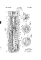
Fig. 1 is a longitudinal sectional view illustrating the elements of a valve in accordance with the invention,
" Fig; 2 is a sectional view taken along the lines 2-2 of Fig.1, a
United States Patent ,Fig. 3 is a sectional view taken along the lines 3-3 of Fig. 1, and I Fig. 4 is a fragmentary perspective view of a portion of the stem means illustrating part of the flow path.
Referring to the drawing in detail and more particularly to Fig. 1 thereof, there isshown a body 10 having a longitudinal bore 11, an inlet fitting 12 at one end thereof, an outlet fitting 14 at the other end thereof, a ported valve seat 15 between the inlet and the outlet, valve means 16 adjacent the inlet for engaging the seat, piston means 17 disposed for longitudinal movement in the bore between the seat and the outlet, tubular stem means 19 carried by the piston for movement therewith extending from adjacent the ported seat to adjacent the outlet, a regulating spring 20 for opposing movement of the piston and adjustment means 21 mounted on the body at the outlet end thereof for varying the force of the regulating spring.
The body 10 is generally cylindrical and the bore 11 extends longitudinally therethrough and is internally threaded at each end to receive the inlet fitting 12 and the outlet fitting 14, both of which are provided with central bores. The bore 11 is formed with an annular radial projection 22 providing oppositely facing shoulders 24 and 25 against the former of which is mounted the centrally ported seat 15. As annular O-ring retainer 26 is disposed in the bore 11 abutting the upstream side of the seat. This retainer has a port of greater diameter than that of the seat port'and has a beveled face on its upstream side and a recess for seating an O-ring 27 adjacent the seat 15 and the body 10. A tubular seat retainer 29 is screw threaded into the inlet end of the bore and has an end abutting the O-ring retainer to maintain the seat and O-ring retainer in position.
The valve means 16 includes a cup-shaped valve member 30 providing a cylindrical bore 31 and having a central aperture 32 in its base and an annular beveled surface 23 adapted to engage the seat 15. ;The diameter of the bore 31 is equal to the diameter of the opening in the ported seat 15. As shown'in Figs. 1 and 2, a generally T-shaped support 28, has a crosspiece 33 which is screw threaded into the bore 11 and has a cylindrical stem 34 which extends longitudinally of the body 10 and fits into the bore 31 to slideably support the member 30 thereon. A helical spring 35 extends between the crosspiece of the support 28 and a suitable shoulder onthe valve member 30 to urge the latter in a direction towards the seat 15.
The piston means 17 comprises a tubular sleeve 36 slideably mounted in the bore 11 and having one end thereof normally abutting the shoulder 25. An annular spring retainer 37 is formed with a central opening 39, a central tubular section 40, and an outer tubular section 38 into which is secured the downstream end of the sleeve 36. The sleeve 36 is internally stepped and cooperates with the section 40 to provide an annular space or recess 41 for receiving an annular ring .42 which protrudes from the upstream open end thereof for a purpose to be described. v
As shown in Figs. 1, 3 and 4, the stem means 19 includes an elongate tubular member 44 extending through the opening 39 in thespring retainer 37 and having an outlet end 45 slidably mounted in the outlet fitting 14. The tubular member has a closed inlet end 46 adjacent theprojection 22 formed with a threaded longitudinal aperture 49 and a pair'of'opposed radial openings 5i) are provided therein adjacent the inlet end. A bolt 51 is adjustably secured in the aperture 49 by a nut 5'2 Within the member 44 and extends through the portedseat 15 and the aperture 32 in the valve member 3% allowinga small clearance therebetween. The bolt head is disposed within the bore Sl andis of greater diameter than the aperture 32 to connect the bolt and themember 30. A tubular spacer 53 formed with a pair of radial apertures 58 midway between the endsthereof extends between the inlet end 46 of the tubular member 44 and the base of-the valve member 30 surrounding but spaced from the shank of the bolt 51. The member 44 is formed with an external flange 54 having an inclined face 55 normally abutting the ring 42, and a helical spring 56 extends between the shoulder 25 and the flange 54 to urge the member 44 in a direction towards the outlet.
The regulating spring 20 is a helical compression spring extending between the spring retainer 37 and an annular guide member 57 adjacent the outlet fitting 14. The regulating spring opposes movement of the piston means 17 in a direction towards the outlet fitting.
The adjustment means 21 comprises a cup-shaped cap 59 which is screw threaded to the external surface of the body at its outlet end and is formed with a central opening 60 through which the outlet fitting extends. Three circuntferentially spaced pins 61 (only one being shown) pass through suitable longitudinal bores in the outlet fitting and have one end bearing against the guide member 57 and the other end' abutting an annular hearing washer 62 which in turn abuts the inner end of the cap 59. A lock nut 64 is screw threaded on the body to retain the cap 59in its adjusted position.
The central bores of the inlet and the outlet fittings are screw threaded to receive tubes for conducting fluid under pressure, and a locking pin 65, mounted in recesses in the outlet fitting and the body 10, prevents movement of that fitting with respect to the body in the event that' the position of the cap 59 is altered.
The invention as described thus far, constitutes a pressure reducer, which operates in the manner about to be discussed.
Prior to installing the apparatus in the line, the cap 59 may be adjusted to. cause the spring 20 to exert a desired force upon the piston means 17 and the bolt 51 is adjusted to provide a desired clearance between the bolt.
head and the inner surface of the base of the valve member 30. The unit is then installed in the fluid conducting. line with the inlet fitting 12 at the high pressure side thereof. The reducer is normally open, the valve memher being held off the seat 15 by the regulating spring acting through the piston means 17 and the spacer 53.
As fluid under pressure enters the apparatus through the fitting 12, it flows around the support 28 and the valve member 30, through the ported seat 15, undergoing a pressure drop, around the inlet end of the member 44 and, as best illustrated in Figs. 1 and 4 by the solid line arrows, into the radial openings 50, and through the member 44 to the outlet. At the same time, the fluid, at its lower or outlet pressure, enters the apertures 58 in the spacer 53 and flows through the aperture 32 in the valve member to enter the bore 31, wherefore the valve member is balanced by equal and opposite forces so that it is urged towards the seat 15 solely by the force of the spring 35.
As the outlet pressure builds up, an increasing force is applied to the regulating spring 20 through the piston means until it is sutficient to overcome the force of the spring, whereupon, the tubular member 44 and the piston means, moving as a unit, begin to compress the spring. The valve member also begins to move towards the outlet under the influence of the spring 35, thus reducing the area between the valve member and the seat 15 and restricting the flow therebetween. When the outlet pressure reaches a predetermined value, the valve member abuts the seat 15 cutting off all flow. A reduction in outlet ressure permits the regulating spring to overcome the decreased force of the pressure acting on the piston means and to force the valve member off the seat by the return travel of the tubular member and the spacer 53. Due to the fact that the regulating spring is affected only by the outlet pressure and not by the inlet pressure, it
will be understood that variations in the inlet pressure, Within predetermined limits, will not affect the outlet pressure but that the same will be maintained constant by reason of the balance of forces due to fluid pressure acting upon the valve member 30. This balance is maintained in spite of inlet pressure variations so that such variations are not transmitted to the regulating spring 20.
To provide for the relief of excess pressure in the reducer discussed heretofore, the tubular member 44 is formed with a circular cross section having a pair of diametrically opposite flat side surfaces 66 extending from the flange 54 through the annular opening 39 in the spring retainer 37 to a point upstream of the outlet end 45 of the tubular member, as shown in Figs. 1 and 4, and the body 10 has a pair of diametrically opposite radial ports 67 downstream of the projection 22.
If, after the main valve has closed, the outlet pressure continues to rise as, for example, by leakage past the seat 15, the force behind the piston means will increase, causing the regulating spring to compress even further whereupon the piston means and the tubular member, urged by the spring 56, move towards the outlet until the head of the bolt 51 abuts the inner surface of the base of the valve member 30, the adjustable clearance between the bolt head and the valve member permitting the desired amount of overtravel of the tubular member rcquired to obtain the correct relief pressure setting.
Any additional increase in the outlet pressure then causes the piston means to move towards the outlet separating the ring 42 from the inclined face 55 of the flange 54 without movement of the tubular member 44. The excess pressure is thereby relieved past the flange 54, and along theflat surfaces 66 to the relief ports 67 in the body 10, as indicated by the broken line arrows on Fig. 1. When the excess pressure is relieved, the regulating spring forces the ring 43 to seat against the flange 54 sealing off the relief flow.
The outlet pressure may be varied by turning the adjustment cap 59 to alter the force exerted on the piston means by the regulating spring 20. The torque is taken up by the bearing washer 62 and the adjustment force is transmitted through the pins 61 to the guide member 57 and the spring 20. Rotation of the cap 59 does not cause rotation of the outlet fitting 14 which is restrained by the locking pin 65. After the desired adjustment is made, the cap is locked in position by the lock nut 64.
For sealing purposes conventional O-rings are disposed at suitable locations such as between the valve member bore 31 and the support 34, the sleeve 36 and the body 10, the outlet fitting 14 and the member 44 and the ring 42 and the sleeve 36.
From the foregoing description, it will be seen that the present invention provides a high pressure, high flow, automatic; pressure reducing valve having a streamlined flow path providing a low pressure drop and having a built-in automatic relief valve. It will also be seen that the valve is light in weight, is compact, efficient and reliable in operation, maintains a constant outlet pressure for any pressure setting within its range regardless of variations in supply pressure and may be adjusted to vary the outlet pressure without disturbing the line connections.
As various changes may be made in the form, construction and arrangement of the parts herein, without departing from the spirit and scope of the invention and without sacrificing any of its advantages, it is to be understood that all matter herein is to be interpreted as illustrative and not in any limiting sense.
I claim:
1. A pressure reducer of the class described comprising, a body havinga, bore, an inlet, an outlet, and a valve seat between said inlet and said outlet provided with a port,.a valve: member in said bore between said inlet and said seat for engaging said seat, tubular piston means in said bore between said outlet and said seat, a
regulating spring opposing movement of said piston means'adapted to yield and permit movement of said piston means in a direction towards said outlet when fluid under pressure in said outlet reaches a predetermined value, tubular stem means carried bysaid piston means for movement therewith, said stem means having an open end adjacent said outlet and having an inlet end adjacent said port formed with inlet means in fluid flow communication with said port, said open outlet end and said inlet means constituting the sole openings in said stem means, spacer means carried by said stem means, said spacer means extending through said port and po sitioned between said stem means and said valve member, and means for urging said member against said spacer meansand towards said seat.
2. A pressure reducer of the class described comprising, a body having a bore, an inlet, an outlet, and a valve seat between said inlet and said outlet provided with a port, a valve member in said bore between said inlet and said seat for engaging said seat and formed with a recess extending towards said inlet, tubular piston means in said bore between said outlet and said seat, a
regulating spring opposing movement of said piston means adapted to yield and permit movement of said piston means in a direction towards said outlet when fluid under pressure in said .outlet reaches a predetermined value, tubular stem means carried by said piston means for movement therewith, said stem means having an open outlet end adjacent said outlet and having an inlet end adjacent said port formed with inlet means in fluid flow communication with said port, said open outlet end and said inlet means constituting the sole openings in said stem means, spacer means carried by said stem means, said spacer means extending through said port and positioned between said stem means and said valve member, a guide member in said bore adjacent said inlet formed with a projection slideably engaging said recess, and means for urging said valve member against said spacer means and towards said seat.
3. A pressure reducer of the class described comprising, a body having a bore, an inlet, an outlet, and a valve seat between said inlet and said outlet provided with a port, a valve member in said bore between said inlet and said seat for engaging said seat and formedwith a recess extending towards said inlet, the area defined by said port being equal to the area defined by said recess, tubular piston means in said bore between said outlet and said seat, a regulating spring opposing movement of said piston means adapted to yield and permit movement of said piston means in a direction towards said outlet when fluid under pressure in said outlet reaches a predetermined value, tubular stem means carried by said piston means for movement therewith, said stem means having an open outlet end adjacent said outlet and having an inlet end adjacent said port formed with inlet means in fluid flow communication with said port, said open outlet end and said inlet means constituting the sole openings in said stem means, spacer means carried by said stem means, said spacer means extending through said port and positioned between said stem means and said valve member, a guide member in said bore adjacent said inlet formed with a projection slideably engaging said recess, and means for urging said valve member against said spacer means and towards said seat.
4. A pressure reducer of the class described comprising, a body having a bore, an inlet, an outlet, and a valve seat between said inlet and said outlet provided with a port, a valve member in said bore between said inlet and said seat for engaging said seat and formed with a recess extending towards said inlet, the area defined by said port being equal to the area defined by said recess, tubular piston means in said bore between said outlet and said seat, a regulating spring opposing movement of said piston means adapted to yield and permit movement of said piston means in a direction towards said outlet when fluid under pressure in said outlet reaches a predetermined value, tubular stem means carried by said piston means'for movement therewith, said stem means having an open outlet end adjacent said outlet and having an inlet end adjacent said port formed with inlet means in fluid flow communication with said said-valve member, said valve member having an aper-' ture' for establishing communication between said recess and said spacer means, a guide memberin said bore adjacent said inlet formed with a projection slideably engaging said recess, and means for urging saidvalve member against said spacer means'and towards said. seat.
5. A pressure reducer of the class described comprising, a body having a bore, an inlet, an outlet, and a valve.
seat between said inlet and said outlet provided with a port, a valve member in said bore between said inlet and saidseat for engaging said seat formed with a recess facing said inlet, tubular piston means in said bore between said outlet and said seat, a regulating spring opposing movement of said'piston means adapted to yield and permit movement of said piston means in a direction towards said outlet when fluid under pressure in said outlet reaches a predetermined value, a tubular member carried by said piston means for movement therewith, said tubular member having an open outlet end adjacent said outlet and having an inlet end adjacent said port formed with inlet means in fluid flow communication with said port, said open outlet end and said inlet means constituting the sole openings iusaid stern means, a spring in said bore for urging said tubular member in a direction towards said outlet, tubular spacer means having a radial aperture carried by said tubular member extending through said port and positioned between said tubular member and said valve member, said valve member havingan aperture for establishing communication between said recess and said spacer-means, a rod adjustably secured to said inlet end of said tubular member and extending through said spacer means and said aperture in said valve member into said recess and formed with an enlarged portion in said recess of greater 7. A pressure reducer of the class described comprise ing, a body having a here, an inlet, an outlet, and a valve seat between said inlet and said outlet provided with a port, a valve member in said bore between said inlet and said seat for engaging said seat, tubular piston means in said bore between said outlet and said seat including valve seat means provided with an opening, a regulating spring opposing movement of said piston means adapted to yield and permit movement of said piston means in a direction towards said outlet when fluid under pressure in said outlet reaches a predetermined value, tubular stem means carried by said piston means for movement therewith extending through said opening and formed with flange means adapted to engage said seat means, said stem means having an open outlet end adjacent said outlet and having an inlet end adjacent said port formed with inlet means in fluid flow communication with said port, said open outlet end and said inlet means constituting the sole openings in said stem means, spacer means extending through said port and positioned between said stem meanstand said valve member, means for urging said member against said spacer means and towards said seat, means for urging said stem means in a direction to cause said flange means to en-,
ing, a body having a bore, an inlet, an outlet, and a valve seat between said inlet andsaid outlet provided with a,
port, a valve member in said bore between said inlet and said seat for engaging said seat and formed with a recess extending towards said inlet, the area defined by said port being equal to the area defined by said recess, piston means in said bore between said outlet and said seatincluding valve seat means provided with an opening, a regulating spring opposing movement of said piston means adapted to yield and permit movement of said piston means in a direction towards said outlet when fluid under pressure in said outlet reaches a predetermined value, tubular stem means carried by said piston means for movement therewith extending through said opening and formed with flange means adapted to engage said seat means, said stem means having an open outlet end adjacent said outlet and having an inlet end adjacent said port formed with inlet means in fluid flow communication with said port, said open outlet end and said inlet means constituting the sole openings in said stem means, spacer means having a radial aperture extending through said port and positioned between said stem means'and said valve member, said valve member having an aperture for establishing communication between said recess and said spacer means, means for urging said member against said spacer means and towards said seat, means for urging said stem means in a direction to cause said flange means to engage said valve seat means, a guide member in said bore adjacent said inlet formedtwith a projection slideably engaging said recess, stop means associated with said stem means to limit the movement thereof in a direction towards said outlet and said body having a port between said piston and said outlet providing communication between said bore and the atmosphere.
9. A pressure reducer 'of the class described compris ing, a body having a bore, an inlet, an outlet, and a valve seat between said inlet and said outlet provided with a port, a valve member in said bore between said inlet and said seatfor engaging said seat and formed with a recess extending towards said inlet, the area defined by said port being:equal to the area defined by said recess, tubular .piston means in said bore between said outlet and "said seat including. valve seat means provided with anopening, a regulatin'g'spring opposing movement of said piston, means adapted to yield and permit movement of said piston means in a direction towards said outlet when fluid under pressure in said outlet reaches a predetermined value, a tubular member carried by said piston means for movement therewith extending through said opening and formed with flange means adapted to engage said seat means, said tubular.
member having an open outlet end adjacent said outlet said open outlet end and said inlet means constituting I the sole openings in said stem means, spacer means having a radial aperture extending through said port and positioned between said tubular member and said valve member, said valve member having an aperture for establishing communication between said recess and said spacer means, means for urging said valve member against said spacer means and towards said seat, means for urging said tubular member in a direction to cause said flange means to engage said valve seat means, a guide member in said bore adjacent said inlet formed with a projection slideably engaging said recess, a rod adjustably secured to said inlet end of said tubular memher and extending through said spacer and said aperture in said valve member into said recess and formed with an enlarged portion in said recess of greater width than said valve member aperture, and said body having a port between said piston and said outlet providing communication between said bore and the atmosphere.
10. Apparatus according to claim 9, wherein a cap formed with a central aperture is adjustably secured to the outlet end of said body and means extend between said cap and said regulating spring for varying the efiectiveness of said spring when the position of said cap on said body isfvaried.
References Cited in the file of this patent UNITED STATES PATENTS 1,210,891 Blanchard et al. Jan. 2, 1917 FOREIGN PATENTS 655,579 Great Britain July 25, 1951
Priority Applications (1)
| Application Number | Priority Date | Filing Date | Title |
|---|---|---|---|
| US453091A US2777458A (en) | 1954-08-30 | 1954-08-30 | Pressure reducer |
Applications Claiming Priority (1)
| Application Number | Priority Date | Filing Date | Title |
|---|---|---|---|
| US453091A US2777458A (en) | 1954-08-30 | 1954-08-30 | Pressure reducer |
Publications (1)
| Publication Number | Publication Date |
|---|---|
| US2777458A true US2777458A (en) | 1957-01-15 |
Family
ID=23799167
Family Applications (1)
| Application Number | Title | Priority Date | Filing Date |
|---|---|---|---|
| US453091A Expired - Lifetime US2777458A (en) | 1954-08-30 | 1954-08-30 | Pressure reducer |
Country Status (1)
| Country | Link |
|---|---|
| US (1) | US2777458A (en) |
Cited By (13)
| Publication number | Priority date | Publication date | Assignee | Title |
|---|---|---|---|---|
| US2888027A (en) * | 1956-12-19 | 1959-05-26 | Weston Hydraulics Ltd | Regulator |
| US3064670A (en) * | 1959-01-13 | 1962-11-20 | Renault | Pressure reducing devices |
| US3168106A (en) * | 1962-06-26 | 1965-02-02 | Bendix Corp | Balanced pressure regulator |
| US3805824A (en) * | 1972-09-25 | 1974-04-23 | Us Navy | Pressure-compensated flow control valve |
| US3822584A (en) * | 1972-11-09 | 1974-07-09 | Freeland Gauge Co | Air flow gaging device |
| US4250919A (en) * | 1979-07-11 | 1981-02-17 | Booth, Inc. | Constant flow valve |
| US4905775A (en) * | 1988-09-15 | 1990-03-06 | Amoco Corporation | Drilling system and flow control apparatus for downhole drilling motors |
| US6053192A (en) * | 1998-10-30 | 2000-04-25 | Ellzey; Steven J. | Low operating force pressure regulator |
| US20040182445A1 (en) * | 2003-03-18 | 2004-09-23 | Gerasimov Yuri Vladimirovich | Velocity head compensated valve assembly |
| US20040250857A1 (en) * | 2001-09-07 | 2004-12-16 | Ernst Bernhard | Reducing valve for compressed gas bottles |
| EP2166423A1 (en) | 2008-09-19 | 2010-03-24 | Isomatic A/S | Balanced fluid valve |
| EP2166424A1 (en) | 2008-09-19 | 2010-03-24 | Isomatic A/S | Fluid regulator |
| US20180039291A1 (en) * | 2015-06-11 | 2018-02-08 | Hydac Fluidtechnik Gmbh | Pressure-regulating valve |
Citations (2)
| Publication number | Priority date | Publication date | Assignee | Title |
|---|---|---|---|---|
| US1210891A (en) * | 1915-08-02 | 1917-01-02 | Ashcroft Mfg Company | Pressure-reducing valve. |
| GB655579A (en) * | 1948-08-17 | 1951-07-25 | Dunlop Rubber Co | An improved pressure reducing valve |
-
1954
- 1954-08-30 US US453091A patent/US2777458A/en not_active Expired - Lifetime
Patent Citations (2)
| Publication number | Priority date | Publication date | Assignee | Title |
|---|---|---|---|---|
| US1210891A (en) * | 1915-08-02 | 1917-01-02 | Ashcroft Mfg Company | Pressure-reducing valve. |
| GB655579A (en) * | 1948-08-17 | 1951-07-25 | Dunlop Rubber Co | An improved pressure reducing valve |
Cited By (18)
| Publication number | Priority date | Publication date | Assignee | Title |
|---|---|---|---|---|
| US2888027A (en) * | 1956-12-19 | 1959-05-26 | Weston Hydraulics Ltd | Regulator |
| US3064670A (en) * | 1959-01-13 | 1962-11-20 | Renault | Pressure reducing devices |
| US3168106A (en) * | 1962-06-26 | 1965-02-02 | Bendix Corp | Balanced pressure regulator |
| US3805824A (en) * | 1972-09-25 | 1974-04-23 | Us Navy | Pressure-compensated flow control valve |
| US3822584A (en) * | 1972-11-09 | 1974-07-09 | Freeland Gauge Co | Air flow gaging device |
| US4250919A (en) * | 1979-07-11 | 1981-02-17 | Booth, Inc. | Constant flow valve |
| US4905775A (en) * | 1988-09-15 | 1990-03-06 | Amoco Corporation | Drilling system and flow control apparatus for downhole drilling motors |
| US6053192A (en) * | 1998-10-30 | 2000-04-25 | Ellzey; Steven J. | Low operating force pressure regulator |
| US20040250857A1 (en) * | 2001-09-07 | 2004-12-16 | Ernst Bernhard | Reducing valve for compressed gas bottles |
| US20040182445A1 (en) * | 2003-03-18 | 2004-09-23 | Gerasimov Yuri Vladimirovich | Velocity head compensated valve assembly |
| US7077158B2 (en) * | 2003-03-18 | 2006-07-18 | Valcor Engineering Corporation | Velocity head compensated valve assembly |
| EP2166423A1 (en) | 2008-09-19 | 2010-03-24 | Isomatic A/S | Balanced fluid valve |
| EP2166424A1 (en) | 2008-09-19 | 2010-03-24 | Isomatic A/S | Fluid regulator |
| US20110174394A1 (en) * | 2008-09-19 | 2011-07-21 | Isomatic A/S | Balanced fluid valve |
| US20110175009A1 (en) * | 2008-09-19 | 2011-07-21 | Soeren Kristoffersen | Fluid regulator |
| US20180039291A1 (en) * | 2015-06-11 | 2018-02-08 | Hydac Fluidtechnik Gmbh | Pressure-regulating valve |
| US10678273B2 (en) * | 2015-06-11 | 2020-06-09 | Hydac Fluidtechnik Gmbh | Pressure-regulating valve |
| EP3308031B1 (en) * | 2015-06-11 | 2021-06-09 | Hydac Fluidtechnik GmbH | Pressure control valve |
Similar Documents
| Publication | Publication Date | Title |
|---|---|---|
| US2777458A (en) | Pressure reducer | |
| US3146720A (en) | Pressure relief means for pump | |
| US2599577A (en) | Balanced fluid pressure regulating valve | |
| US3073342A (en) | Airless coupling | |
| US2731975A (en) | boals | |
| US2797061A (en) | Solenoid operated shut-off valve | |
| US3722536A (en) | Monitor pressure regulator assembly | |
| US2748797A (en) | Pneumatic time-delay fuse | |
| EP3226097A1 (en) | Axial valve for controlling the differential pressure between a delivery branch and a return branch of a hydraulic circuit | |
| GB586727A (en) | Improvements in or relating to pressure regulating valves | |
| US3807442A (en) | Excess flow check valve with variable closing flow rate | |
| US2642887A (en) | Unloading valve | |
| US3091213A (en) | Fluid pressure operated warning device | |
| US2967543A (en) | Flow regulating valve | |
| US2675649A (en) | Pressure reducing valve | |
| US2853096A (en) | Relief valve assemblies | |
| US2970609A (en) | Shut-off valve | |
| US2568982A (en) | Mechanically operated check valve | |
| US2687743A (en) | Pressure reducing valve with overpressure release | |
| US2917073A (en) | Pressure reducing valve | |
| US3452776A (en) | Pressure control valve | |
| US3161207A (en) | Control device for controlling the upper and lower limits of the pressure in a fluid flow line | |
| US3351086A (en) | Adjustable straight-through flow regulator | |
| US2854995A (en) | Relief valve | |
| US2573761A (en) | Valve |