US2967543A - Flow regulating valve - Google Patents
Flow regulating valve Download PDFInfo
- Publication number
- US2967543A US2967543A US512538A US51253855A US2967543A US 2967543 A US2967543 A US 2967543A US 512538 A US512538 A US 512538A US 51253855 A US51253855 A US 51253855A US 2967543 A US2967543 A US 2967543A
- Authority
- US
- United States
- Prior art keywords
- outlet
- valving
- impellor
- valve
- regulating valve
- Prior art date
- Legal status (The legal status is an assumption and is not a legal conclusion. Google has not performed a legal analysis and makes no representation as to the accuracy of the status listed.)
- Expired - Lifetime
Links
Images
Classifications
-
- G—PHYSICS
- G05—CONTROLLING; REGULATING
- G05D—SYSTEMS FOR CONTROLLING OR REGULATING NON-ELECTRIC VARIABLES
- G05D7/00—Control of flow
- G05D7/01—Control of flow without auxiliary power
- G05D7/0126—Control of flow without auxiliary power the sensing element being a piston or plunger associated with one or more springs
-
- Y—GENERAL TAGGING OF NEW TECHNOLOGICAL DEVELOPMENTS; GENERAL TAGGING OF CROSS-SECTIONAL TECHNOLOGIES SPANNING OVER SEVERAL SECTIONS OF THE IPC; TECHNICAL SUBJECTS COVERED BY FORMER USPC CROSS-REFERENCE ART COLLECTIONS [XRACs] AND DIGESTS
- Y10—TECHNICAL SUBJECTS COVERED BY FORMER USPC
- Y10T—TECHNICAL SUBJECTS COVERED BY FORMER US CLASSIFICATION
- Y10T137/00—Fluid handling
- Y10T137/7722—Line condition change responsive valves
- Y10T137/7754—Line flow effect assisted
-
- Y—GENERAL TAGGING OF NEW TECHNOLOGICAL DEVELOPMENTS; GENERAL TAGGING OF CROSS-SECTIONAL TECHNOLOGIES SPANNING OVER SEVERAL SECTIONS OF THE IPC; TECHNICAL SUBJECTS COVERED BY FORMER USPC CROSS-REFERENCE ART COLLECTIONS [XRACs] AND DIGESTS
- Y10—TECHNICAL SUBJECTS COVERED BY FORMER USPC
- Y10T—TECHNICAL SUBJECTS COVERED BY FORMER US CLASSIFICATION
- Y10T137/00—Fluid handling
- Y10T137/7722—Line condition change responsive valves
- Y10T137/7781—With separate connected fluid reactor surface
- Y10T137/7784—Responsive to change in rate of fluid flow
- Y10T137/7792—Movable deflector or choke
Definitions
- This invention relates to a valve device, and more particularly to a valve adapted to permit the iiow of a predetermined volume of fluid in spite of Wide variations in the pressure of the iluid.
- a ilow regulating valve including a casing having a passage interconnecting an inlet and an outlet and to provide in said passage a ilow regulating valve having an impellor portion subjected to fluid flow through the passage and a valving portion adjacent the outlet and movable by the impellor to control the flow of Huid through the outlet.
- Another object of the invention is to provide a valve of the type described in the preceding paragraphs with a spring constantly biasing the valving portion in one direction and to provide said valving portion with an enlarged end adjacent the outlet and positioned to at least partially offset departures from a straight line operation of the valve caused by the characteristics of the spring.
- Fig. l is an end elevational view of a ow regulating valve embodying the invention.
- Fig. 2 is a top plan view of the valve shown in Fig. l;
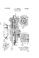
- Fig. 3 is an enlarged cross sectional view of the valve taken along line 3-3 of Fig. l;
- Fig. 4 is a sectional view taken along line 4 4 of Fig. 3;
- Fig. 5 is another sectional view taken along line 5-5 of Fig. 3.
- the low regulating valve of the present invention includes a generally rectangular casing provided with a generally cylindrical passage 11 extending therethrough, a tting 12 secured to one end of the casing by means of a flanged hexagonal nut 13 is provided with an opening 14 forming an inlet into the passage 11.
- Means are provided for dividing the passage 11 into ICC a plurality of sections including an inlet section 15, an impellor section 16 and an outlet section 17.
- the foregoing means include a disk 18 seated upon a shoulder 19 formed in the casing and held in position by a sleeve 20 pressed into the inlet section of the passage.
- the disk 18 is provided with three holes 21 to permit iluid flow from the inlet chamber into the impellor chamber and is also provided with a central opening 22 through which a valving member 23 extends.
- the impellor and outet sections are separated by a disk 25 having a single opening 26 therein through which a valving portion 27 of the valving member 23 extends.
- the valving portion 27 is provided with an axially extending hollow 28 com municating at one end with a pair of openings 29 open ing into the impellor chamber with the valving portion 27 being open at its other end 30 so as to permit communication between the hollow 28 and the outlet chamber 17 Extending radially outward from the outlet chamber 17 is an outlet 31 and positioned adjacent the outlet is a valve seat 32 positioned to cooperate with the valving portion 27 and thus control the flow of iluid through the hollow 28 and into the outlet 31. It will be noted that the valving portion 27 is provided with an enlarged end 33 in the outlet chamber, the function of which will be later described.
- an impelor 35 Secured to the valving member 23 in the impellor chamber 16 is an impelor 35 which is in the form of a disk having an edge slightly spaced from the surrounding side walls of the impellor chamber so that the impellor partially obstructs the flow of iluid through the chamber 16, and thereby creates a pressure diierential on opposite sides of the impellor, serving to urge the valving member 23 and its attached valving portion 27 in a direction toward the valve seat 32 to reduce the ilow through the outlet 31.
- Opposing the bias of the impellor is a spring 36 seated at one end against a flange portion 37 formed on a colar 38 surrounding the valving member 23.
- a pair of nuts 39 permit regulation of the tension of the spring 36 to vary its eiect. The opposite end of the spring seats in a recess formed in the disk 18.
- the valve seat 32 is in the form of two tapered coaxial recesses formed in the end of a rod 40 threaded as indicated and engaging complementary threads formed in the casing 10.
- the opposite end of the rod 40 is formed into a hexagonal nut 41 so that the same may be rotated by a suitable wrench and a lock nut 42 is provided for locking the rod 40 in any desired position. Leakage along the rod is prevented by means of an O-ring seal 43.
- the spring 36 will not have a straight line degree of compressibility, but rather a plot of its resistance to compression would resemble a tangent curve. Thus the more the spring is compressed, the more force is required to compress it further.
- Means are provided in the iluid regulating device illustrated for compensating at least in p-art for this characteristic of springs. To this end the enlarged portion 33 is positioned in the outlet chamber generally opposite the outlet 31 so that accelerated fluid ow in the outlet chamber (when the device is operating under high inlet pressure) is across the outer face of the enlarged portion 33.
- the enlarged portion 33 acts in the nature of a second impellor, urging the valving member and the valving portion toward further movement toward the valve seat 32, and thus in opposition to the spring 36.
- This action of the enlarged portion 33 is principally manifest under high inlet pressure, under which conditions the spring 36 will be under its greatest compression.
- the ow regulating device of the present invention may readily be made of corrosion resistant materials, such as stainless steel, and thus is readily adaptable for use in systems wherein the liquid whose ow is to be regulated is of a corrosive nature.
- the adjustability of the seat 32 permits adjustment of the device to pass diierent quantities of uid regardless of pressure, the seat may be tixed if such adjustability is not desired.
- a ow regulating valve comprising a casing; an elongated generally cylindrical bore in the casing; means in said casing dividing the bore into an inlet section, an outlet section, and an intermediate impellor section; an inlet in the casing opening into said inlet section; an outlet in the casing opening radially into the outlet section; a'valving member extending into each of said sections and mounted in said dividing means for movement axially in said bore, said valving member including a cylindrical valving portion positioned in the impellor and outlet sections, said valving portion having an open end in the outlet section, an opening in the impellor section and a passage therein interconnecting the opening and the open end to establish communication between the last mentioned sections through said valving portion; a valve seat in the outlet section positioned in the path of movement of said end of the valving portion; means biasing the valving member toward movement in a direction separating said end of the valving portion from the valve seat; an impellor secured to the valving member in the
- a ow regulating valve comprising a casing having an inlet and an outlet, a passage in the casing interconnecting the inlet and the outlet, a valve seat comprising means defining a recess in the casing adjacent the outlet, a valving member movably mounted in the casing and having a valving portion movable therewith coaXially toward and away from said seat, said valving portion having an opening in communication with the inlet and arranged to direct fluid ow at said valve seat to impingc thereagainst and be redirected thereby in a substantially opposite direction of flow and pass from the passage through said outlet, means biasing the valving member in a direction away from said seat, an impellor connected to the valving member and having a portion positioned in said passage partially to obstruct the ow of fluid therethrough to create a pressure differential on opposite sides of the impellor urging the valving portion toward said valve seat, said valving portion being annularly enlarged at the end thereof adjacent said valve seat,
Description
Jan. 1o, 1961 A. A. wERGUT-z 2,967,543
FLow REGULATING VALVE Filed June '1, 1955 "10 I Q m.
@Mdm/@$555,
BYJJ
United States Patent O FLOW REGULATING VALVE Alfred H. Viergutz, Chicago, Ill., assignor to The W. A. Kates Company, a corporation of Illinois Filed June 1, 1955, Ser. No. 512,538
2 Claims. (Cl. 137-4842) This invention relates to a valve device, and more particularly to a valve adapted to permit the iiow of a predetermined volume of fluid in spite of Wide variations in the pressure of the iluid.
It is the general object of the present invention to produce a new and improved regulating valve of the character described.
It is a more specific object of the invention to provide a ilow regulating valve having a movable valving portion controlling ow of uid through the outlet of the valve and to provide therein means for moving the valving portion in response to iluid flow through the valve thereby to regulate the quantity of uid permitted to ow through the outlet in spite of changes in the pressure of the fluid.
It is a more specific object of the invention to provide a ilow regulating valve including a casing having a passage interconnecting an inlet and an outlet and to provide in said passage a ilow regulating valve having an impellor portion subjected to fluid flow through the passage and a valving portion adjacent the outlet and movable by the impellor to control the flow of Huid through the outlet.
Another object of the invention is to provide a valve of the type described in the preceding paragraphs with a spring constantly biasing the valving portion in one direction and to provide said valving portion with an enlarged end adjacent the outlet and positioned to at least partially offset departures from a straight line operation of the valve caused by the characteristics of the spring.
Other and further objects of the invention will be readily apparent from the following description and drawings, in which:
Fig. l is an end elevational view of a ow regulating valve embodying the invention;
Fig. 2 is a top plan view of the valve shown in Fig. l;
Fig. 3 is an enlarged cross sectional view of the valve taken along line 3-3 of Fig. l;
Fig. 4 is a sectional view taken along line 4 4 of Fig. 3; and,
Fig. 5 is another sectional view taken along line 5-5 of Fig. 3.
While this invention is susceptible of embodiments in many different forms, there is shown in the drawings and will herein be described in detail one specific embodiment, with the understanding that the present disclosure is to be considered as an exemplication of the principles of the invention and is not intended to limit the invention to the embodiment illustrated. The scope of the invention will be pointed out in the appended claims.
Referring now to the drawings, it will be noted that the low regulating valve of the present invention includes a generally rectangular casing provided with a generally cylindrical passage 11 extending therethrough, a tting 12 secured to one end of the casing by means of a flanged hexagonal nut 13 is provided with an opening 14 forming an inlet into the passage 11.
Means are provided for dividing the passage 11 into ICC a plurality of sections including an inlet section 15, an impellor section 16 and an outlet section 17. The foregoing means include a disk 18 seated upon a shoulder 19 formed in the casing and held in position by a sleeve 20 pressed into the inlet section of the passage. The disk 18 is provided with three holes 21 to permit iluid flow from the inlet chamber into the impellor chamber and is also provided with a central opening 22 through which a valving member 23 extends. The impellor and outet sections are separated by a disk 25 having a single opening 26 therein through which a valving portion 27 of the valving member 23 extends. The valving portion 27 is provided with an axially extending hollow 28 com municating at one end with a pair of openings 29 open ing into the impellor chamber with the valving portion 27 being open at its other end 30 so as to permit communication between the hollow 28 and the outlet chamber 17 Extending radially outward from the outlet chamber 17 is an outlet 31 and positioned adjacent the outlet is a valve seat 32 positioned to cooperate with the valving portion 27 and thus control the flow of iluid through the hollow 28 and into the outlet 31. It will be noted that the valving portion 27 is provided with an enlarged end 33 in the outlet chamber, the function of which will be later described.
Secured to the valving member 23 in the impellor chamber 16 is an impelor 35 which is in the form of a disk having an edge slightly spaced from the surrounding side walls of the impellor chamber so that the impellor partially obstructs the flow of iluid through the chamber 16, and thereby creates a pressure diierential on opposite sides of the impellor, serving to urge the valving member 23 and its attached valving portion 27 in a direction toward the valve seat 32 to reduce the ilow through the outlet 31. Opposing the bias of the impellor is a spring 36 seated at one end against a flange portion 37 formed on a colar 38 surrounding the valving member 23. A pair of nuts 39 permit regulation of the tension of the spring 36 to vary its eiect. The opposite end of the spring seats in a recess formed in the disk 18. j
The valve seat 32 is in the form of two tapered coaxial recesses formed in the end of a rod 40 threaded as indicated and engaging complementary threads formed in the casing 10. The opposite end of the rod 40 is formed into a hexagonal nut 41 so that the same may be rotated by a suitable wrench and a lock nut 42 is provided for locking the rod 40 in any desired position. Leakage along the rod is prevented by means of an O-ring seal 43. By reason of the foregoing, the location of the valve seat 32 relative to the end of the valving member 27 maybe varied, and thus the capacity of the fluid regulating device may be changed as circumstances require.
As the pressure of fluid entering the inlet 14 may increase, increased fluid flow past the impellor 35 increases the pressure differential on opposite sides thereof, thereby moving the valving member and its valving por tion against the bias of the spring toward a position throttling the ilow into the outlet 31 by proximating the open end 30 of the valving portion and the valve seat 32.
lt is recognized that the spring 36 will not have a straight line degree of compressibility, but rather a plot of its resistance to compression would resemble a tangent curve. Thus the more the spring is compressed, the more force is required to compress it further. Means are provided in the iluid regulating device illustrated for compensating at least in p-art for this characteristic of springs. To this end the enlarged portion 33 is positioned in the outlet chamber generally opposite the outlet 31 so that accelerated fluid ow in the outlet chamber (when the device is operating under high inlet pressure) is across the outer face of the enlarged portion 33. Because of the reduction in pressure resulting from increased velocity of ow, the enlarged portion 33 acts in the nature of a second impellor, urging the valving member and the valving portion toward further movement toward the valve seat 32, and thus in opposition to the spring 36. This action of the enlarged portion 33 is principally manifest under high inlet pressure, under which conditions the spring 36 will be under its greatest compression.
The ow regulating device of the present invention may readily be made of corrosion resistant materials, such as stainless steel, and thus is readily adaptable for use in systems wherein the liquid whose ow is to be regulated is of a corrosive nature. Clearly, while the adjustability of the seat 32 permits adjustment of the device to pass diierent quantities of uid regardless of pressure, the seat may be tixed if such adjustability is not desired.
Iclaim:
1. A ow regulating valve comprising a casing; an elongated generally cylindrical bore in the casing; means in said casing dividing the bore into an inlet section, an outlet section, and an intermediate impellor section; an inlet in the casing opening into said inlet section; an outlet in the casing opening radially into the outlet section; a'valving member extending into each of said sections and mounted in said dividing means for movement axially in said bore, said valving member including a cylindrical valving portion positioned in the impellor and outlet sections, said valving portion having an open end in the outlet section, an opening in the impellor section and a passage therein interconnecting the opening and the open end to establish communication between the last mentioned sections through said valving portion; a valve seat in the outlet section positioned in the path of movement of said end of the valving portion; means biasing the valving member toward movement in a direction separating said end of the valving portion from the valve seat; an impellor secured to the valving member in the impellor section of the bore and partially obstructing the ow of iluid therethrough to create a pressure differential on opposite sides of the impellor sufficient to move the valving member toward the valve seat against the bias of the biasing means, and an enlarged generally annular portion formed on said open end and positioned coaxially of the valving portion said enlarged portion being subject to ow of uid from said outlet section radially outwardly through said outlet and said enlarged portion being positioned adjacent the radial outlet to urge the valving member toward movement in parallel with said impellor.
2. A ow regulating valve comprising a casing having an inlet and an outlet, a passage in the casing interconnecting the inlet and the outlet, a valve seat comprising means defining a recess in the casing adjacent the outlet, a valving member movably mounted in the casing and having a valving portion movable therewith coaXially toward and away from said seat, said valving portion having an opening in communication with the inlet and arranged to direct fluid ow at said valve seat to impingc thereagainst and be redirected thereby in a substantially opposite direction of flow and pass from the passage through said outlet, means biasing the valving member in a direction away from said seat, an impellor connected to the valving member and having a portion positioned in said passage partially to obstruct the ow of fluid therethrough to create a pressure differential on opposite sides of the impellor urging the valving portion toward said valve seat, said valving portion being annularly enlarged at the end thereof adjacent said valve seat, said enlarged portion being subject to the pressure of the uid redirected by said valve seat to urge the valving member toward said valve seat.
References Cited in the le of this patent UNITED STATES PATENTS Re. 23,487 McCabe Apr. 29, 1952 2,307,949 Phillips Jan. 12, 1943 2,411,392 Saville Nov. 19, 1946 2,472,787 Brown June 14, 1949 2,584,418 Branson Feb. 5, 1952 2,668,555 Bartolat Feb. 9, 1954 2,698,027 Branson Dec. 28, 1954 FORETGN PATENTS 706,674 Great Britain Mar. 3l, 1954 304,232 Switzerland Mar. 1, 1955
Priority Applications (1)
| Application Number | Priority Date | Filing Date | Title |
|---|---|---|---|
| US512538A US2967543A (en) | 1955-06-01 | 1955-06-01 | Flow regulating valve |
Applications Claiming Priority (1)
| Application Number | Priority Date | Filing Date | Title |
|---|---|---|---|
| US512538A US2967543A (en) | 1955-06-01 | 1955-06-01 | Flow regulating valve |
Publications (1)
| Publication Number | Publication Date |
|---|---|
| US2967543A true US2967543A (en) | 1961-01-10 |
Family
ID=24039522
Family Applications (1)
| Application Number | Title | Priority Date | Filing Date |
|---|---|---|---|
| US512538A Expired - Lifetime US2967543A (en) | 1955-06-01 | 1955-06-01 | Flow regulating valve |
Country Status (1)
| Country | Link |
|---|---|
| US (1) | US2967543A (en) |
Cited By (11)
| Publication number | Priority date | Publication date | Assignee | Title |
|---|---|---|---|---|
| US3196902A (en) * | 1962-09-27 | 1965-07-27 | Multiplex Company | Flow control device |
| US3204659A (en) * | 1962-08-29 | 1965-09-07 | Liquid Controls Corp | Liquid flow control device |
| US4699166A (en) * | 1981-07-21 | 1987-10-13 | Harold Gold | Hydraulic fuse valve assembly |
| US4832595A (en) * | 1986-07-31 | 1989-05-23 | Eads James B | Torch nozzle assembly |
| US4922956A (en) * | 1988-06-30 | 1990-05-08 | Systems Specialties | Fluid flow control regulator |
| US5000219A (en) * | 1988-06-30 | 1991-03-19 | Systems Specialties | Fluid flow control regulator |
| US5070902A (en) * | 1990-12-05 | 1991-12-10 | Mcmurry Oil Tools, Inc. | Lateral orifice water regulator |
| US5167253A (en) * | 1990-09-19 | 1992-12-01 | Alsthom Fluides Sapag | Flow regulator valve |
| US6196259B1 (en) | 1998-03-12 | 2001-03-06 | Flow Design, Inc. | Method and apparatus for regulating and terminating fluid flow |
| US6688319B2 (en) | 2002-04-10 | 2004-02-10 | Flow Design, Inc. | Flow regulating control valve and method for regulating fluid flow |
| US20130025712A1 (en) * | 2011-07-26 | 2013-01-31 | Horst Thiele Maschinenbau-Hydraulische Gerate GmbH | Pipe break valve device |
Citations (9)
| Publication number | Priority date | Publication date | Assignee | Title |
|---|---|---|---|---|
| US2307949A (en) * | 1941-08-05 | 1943-01-12 | Pump Engineering Service Corp | Flow restrictor |
| US2411392A (en) * | 1943-06-26 | 1946-11-19 | Cons Vultee Aircraft Corp | Control mechanism for hydraulically operated devices |
| US2472787A (en) * | 1945-08-24 | 1949-06-14 | Chicago Faucet Company | Flow regulator |
| US2584418A (en) * | 1948-04-19 | 1952-02-05 | Robertshaw Fulton Controls Co | Constant flow valve |
| USRE23487E (en) * | 1952-04-29 | Fill and discharge valve for lique | ||
| US2668555A (en) * | 1951-04-07 | 1954-02-09 | Albert F Bartolat | Excess flow cutoff valve with adjustable valve seat |
| GB706674A (en) * | 1952-08-05 | 1954-03-31 | Phillips Petroleum Co | Improvements in or relating to excess flow valves |
| US2698027A (en) * | 1949-01-19 | 1954-12-28 | Robertshaw Fulton Controls Co | Combined stop and flow control valve units |
| CH304232A (en) * | 1951-06-08 | 1954-12-31 | Balass Valentin | Device for controlling at least one organ under the action of a pressure fluid. |
-
1955
- 1955-06-01 US US512538A patent/US2967543A/en not_active Expired - Lifetime
Patent Citations (9)
| Publication number | Priority date | Publication date | Assignee | Title |
|---|---|---|---|---|
| USRE23487E (en) * | 1952-04-29 | Fill and discharge valve for lique | ||
| US2307949A (en) * | 1941-08-05 | 1943-01-12 | Pump Engineering Service Corp | Flow restrictor |
| US2411392A (en) * | 1943-06-26 | 1946-11-19 | Cons Vultee Aircraft Corp | Control mechanism for hydraulically operated devices |
| US2472787A (en) * | 1945-08-24 | 1949-06-14 | Chicago Faucet Company | Flow regulator |
| US2584418A (en) * | 1948-04-19 | 1952-02-05 | Robertshaw Fulton Controls Co | Constant flow valve |
| US2698027A (en) * | 1949-01-19 | 1954-12-28 | Robertshaw Fulton Controls Co | Combined stop and flow control valve units |
| US2668555A (en) * | 1951-04-07 | 1954-02-09 | Albert F Bartolat | Excess flow cutoff valve with adjustable valve seat |
| CH304232A (en) * | 1951-06-08 | 1954-12-31 | Balass Valentin | Device for controlling at least one organ under the action of a pressure fluid. |
| GB706674A (en) * | 1952-08-05 | 1954-03-31 | Phillips Petroleum Co | Improvements in or relating to excess flow valves |
Cited By (12)
| Publication number | Priority date | Publication date | Assignee | Title |
|---|---|---|---|---|
| US3204659A (en) * | 1962-08-29 | 1965-09-07 | Liquid Controls Corp | Liquid flow control device |
| US3196902A (en) * | 1962-09-27 | 1965-07-27 | Multiplex Company | Flow control device |
| US4699166A (en) * | 1981-07-21 | 1987-10-13 | Harold Gold | Hydraulic fuse valve assembly |
| US4832595A (en) * | 1986-07-31 | 1989-05-23 | Eads James B | Torch nozzle assembly |
| US4922956A (en) * | 1988-06-30 | 1990-05-08 | Systems Specialties | Fluid flow control regulator |
| US5000219A (en) * | 1988-06-30 | 1991-03-19 | Systems Specialties | Fluid flow control regulator |
| US5167253A (en) * | 1990-09-19 | 1992-12-01 | Alsthom Fluides Sapag | Flow regulator valve |
| US5070902A (en) * | 1990-12-05 | 1991-12-10 | Mcmurry Oil Tools, Inc. | Lateral orifice water regulator |
| US6196259B1 (en) | 1998-03-12 | 2001-03-06 | Flow Design, Inc. | Method and apparatus for regulating and terminating fluid flow |
| US6688319B2 (en) | 2002-04-10 | 2004-02-10 | Flow Design, Inc. | Flow regulating control valve and method for regulating fluid flow |
| US20130025712A1 (en) * | 2011-07-26 | 2013-01-31 | Horst Thiele Maschinenbau-Hydraulische Gerate GmbH | Pipe break valve device |
| US9234600B2 (en) * | 2011-07-26 | 2016-01-12 | Horst Thiele Maschinenbau-Hydraulische Gerate GmbH | Pipe break valve device |
Similar Documents
| Publication | Publication Date | Title |
|---|---|---|
| US5462081A (en) | Excess flow valve | |
| US2584418A (en) | Constant flow valve | |
| US3791619A (en) | Valve construction | |
| US4436111A (en) | Hydraulic fuse valve | |
| US3598145A (en) | Check valve | |
| US3667722A (en) | Proportional valve | |
| US2967543A (en) | Flow regulating valve | |
| US3794063A (en) | Refrigerant throttling valve | |
| US2821209A (en) | Hydraulic fuses | |
| US3472275A (en) | Flow regulator apparatus | |
| US3722536A (en) | Monitor pressure regulator assembly | |
| US2748797A (en) | Pneumatic time-delay fuse | |
| US3517697A (en) | Pressure regulating valve | |
| US2872939A (en) | Flow control valve | |
| US2788192A (en) | Fluid flow and pressure control valve | |
| EP0118542A1 (en) | Hydraulic fuse valve assembly | |
| US3674237A (en) | Flush valve | |
| US2917075A (en) | Flow control valve | |
| US3561483A (en) | Dual fluid mixing valve with servomotor | |
| US3115892A (en) | Flow controller | |
| US3156253A (en) | Pressure regulating valve and combination on-off valve | |
| US2538133A (en) | Control valve | |
| US2042462A (en) | Fluid flow control device | |
| US2441220A (en) | Valve | |
| US3601148A (en) | Fluid-pressure-regulating valve device |