US2744404A - Laminated lock body - Google Patents
Laminated lock body Download PDFInfo
- Publication number
- US2744404A US2744404A US27300052A US2744404A US 2744404 A US2744404 A US 2744404A US 27300052 A US27300052 A US 27300052A US 2744404 A US2744404 A US 2744404A
- Authority
- US
- United States
- Prior art keywords
- recess
- laminations
- plate
- lock body
- edges
- Prior art date
- Legal status (The legal status is an assumption and is not a legal conclusion. Google has not performed a legal analysis and makes no representation as to the accuracy of the status listed.)
- Expired - Lifetime
Links
- 238000003475 lamination Methods 0.000 description 17
- 238000010276 construction Methods 0.000 description 3
- 239000002184 metal Substances 0.000 description 3
- 238000003754 machining Methods 0.000 description 2
- 238000005452 bending Methods 0.000 description 1
- 239000007779 soft material Substances 0.000 description 1
Images
Classifications
-
- E—FIXED CONSTRUCTIONS
- E05—LOCKS; KEYS; WINDOW OR DOOR FITTINGS; SAFES
- E05B—LOCKS; ACCESSORIES THEREFOR; HANDCUFFS
- E05B67/00—Padlocks; Details thereof
- E05B67/02—Cases
-
- Y—GENERAL TAGGING OF NEW TECHNOLOGICAL DEVELOPMENTS; GENERAL TAGGING OF CROSS-SECTIONAL TECHNOLOGIES SPANNING OVER SEVERAL SECTIONS OF THE IPC; TECHNICAL SUBJECTS COVERED BY FORMER USPC CROSS-REFERENCE ART COLLECTIONS [XRACs] AND DIGESTS
- Y10—TECHNICAL SUBJECTS COVERED BY FORMER USPC
- Y10T—TECHNICAL SUBJECTS COVERED BY FORMER US CLASSIFICATION
- Y10T29/00—Metal working
- Y10T29/49—Method of mechanical manufacture
- Y10T29/49826—Assembling or joining
- Y10T29/49908—Joining by deforming
- Y10T29/49938—Radially expanding part in cavity, aperture, or hollow body
-
- Y—GENERAL TAGGING OF NEW TECHNOLOGICAL DEVELOPMENTS; GENERAL TAGGING OF CROSS-SECTIONAL TECHNOLOGIES SPANNING OVER SEVERAL SECTIONS OF THE IPC; TECHNICAL SUBJECTS COVERED BY FORMER USPC CROSS-REFERENCE ART COLLECTIONS [XRACs] AND DIGESTS
- Y10—TECHNICAL SUBJECTS COVERED BY FORMER USPC
- Y10T—TECHNICAL SUBJECTS COVERED BY FORMER US CLASSIFICATION
- Y10T70/00—Locks
- Y10T70/40—Portable
- Y10T70/413—Padlocks
- Y10T70/487—Parts, accessories, attachments and adjuncts
- Y10T70/489—Housings
Definitions
- This invention relates to a laminated lock body and more particularly to a novel construction for laminated padlocks of the type illustrated in my co-pending application Serial No. 286,730, tiled May 8, 1952.
- lt is an object of this invention to provide improved means in addition to those disclosed in the co-pending application of Stephen V. Zavoico, Serial No. 316,152, tiled October 22, 1952, and now Patent No. 2,662,385, for securing a name plate or the like to the body of a laminated lock.
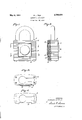
- Fig. 1 is a iront view of a padlock embodying my invention.
- Fig. 2 is a side View of the said lock, partly in central vertical section.
- Fig. 3 is a sectional top view on line 3--3 of Fig. 1.
- Fig. 4 is a plan view, on line 4 4 of Fig. 1, showing one of the laminations in the lock body.
- the numeral 5 denotes the body of my improved padlock which is constructed of a series of laminations that are secured together by rivets 6.
- lt is desirable in such laminated locks to providemeans for readily attaching a name plate to the side of said body in an inexpensive manner, so as to enhance the appearance of the lock without unduly increasing the cost of its construction. It is also important that such name plates be attached in such a manner that the edges of the plate are protected so as to present a smooth appearance and provide a ush surface across the face of the lock and over the marginal portions of the name plate.
- the laminations 9 and 10 which are respectively at the top and bottom of the said recess, are each provided with a notch 11, as shown in Fig. 4, which is deeper than the notch 7, so as to form horizontal grooves at the top and bottom of the said recess.
- the name plate 12 is preferably made of a substantially soft sheet metal and the side edges thereof rnay be either square or beveled as shown in Fig. 3; the top and bottom of the said name plate being provided with inwardly turned flanges 13 and 14 for stiifening the plate against distortion.
- the flanges 13 and 14 will enter the notches 11 of the laminations 9 and 10. After the plate has been thus attached, all of the edges of the plate will be protected by the sides of the recess and the said flanges 13 and 14 will prevent the plate from buckling and becoming loosened in the said recess.
- my invention provides a plate-receiving recess in the face of a laminated lock by forming a notch in each of the lmninations as they are produced in a stamping operation so that no further machining operations are required for said recess.
- grooves are provided at opposite edges of the recess without machining operations and these grooves permit the use of stiifening ribs for preventing bending or other deformation of the name plate after it has been secured to the lock body.
- a laminated lock body constructed of a series of juxtapositioned laminations each having a notch in an edge portion thereof forming a recess in the side of the said body, certain of said laminations having a substantially deeper notch to provide grooves along opposite sides of the said recess and a plate fitting within said recess and having flange portions extending into said grooves.
- a lock construction including a body formed of a series of laminations secured together in juxtaposition, certain of said laminations having a shallow notch in an edge portion thereof with undercut ends and others of said laminations having a deeper notch whereby said body is provided with a shallow recess in the face thereof having undercut side edges and elongated grooves at the top and bottom edges of said recess and a plate tting within said recess and having portions extending into said grooves.
- a laminated lock body constructed of a plurality of juxtapositioned laminations secured together and formed to jointly provide a recess in the face of said body having undercut side edges and grooves at the top and bottom edges thereof, and a plate of substantially soft material in said recess'having edge portions extending into the said undercut edges and stiflening anges extending inwardly from said plate into said grooves.
- a laminated lock body For a laminated lock body, a plurality of identical laminations adapted to be secured together and forming a portion of the lock body, said laminations having identical notches in their corresponding edges, the side edges of the notches being undercut, said undercut extending from said corresponding edges, whereby, when the said laminations are assembled, there is provided a recess in the lock body having undercut side edges adapted to receive the opposite edges of a name plate disposed in said recess.
Landscapes
- Looms (AREA)
Description
May 8, 1956 N. J. vlLE 2,744,404
LAMINATED Loox BODY Filed Feb. 23, 1952 INVENTOR. /VoFw/v/v J VILE.
BY q I H T TOPNEK UnitedStates Patent O 2,744,404 LAMINATED LOCK BODY Norman J. Vile, New Britain, Conn., assignor to The Eagle Lock Company, Terryville, Conn., a corporation of Connecticut Application February 23, 1952, Serial No. 273,000 4 Claims. (Cl. 70-52) This invention relates to a laminated lock body and more particularly to a novel construction for laminated padlocks of the type illustrated in my co-pending application Serial No. 286,730, tiled May 8, 1952.
lt is an object of this invention to provide improved means in addition to those disclosed in the co-pending application of Stephen V. Zavoico, Serial No. 316,152, tiled October 22, 1952, and now Patent No. 2,662,385, for securing a name plate or the like to the body of a laminated lock.
It is a further object of the invention to provide a lock body which is constructed of a series of liminations that are so formedV as to provide a recess in the face of the completed lock body when the said laminations are juxtapositioned and secured together.
Further objects and advantages of this invention will be more clearly understood from the following description and from the accompanying drawings in which:
Fig. 1 is a iront view of a padlock embodying my invention.
Fig. 2 is a side View of the said lock, partly in central vertical section.
Fig. 3 is a sectional top view on line 3--3 of Fig. 1.
Fig. 4 is a plan view, on line 4 4 of Fig. 1, showing one of the laminations in the lock body.
In the embodiment of my invention which is shown in the said drawings, the numeral 5 denotes the body of my improved padlock which is constructed of a series of laminations that are secured together by rivets 6.
lt is desirable in such laminated locks to providemeans for readily attaching a name plate to the side of said body in an inexpensive manner, so as to enhance the appearance of the lock without unduly increasing the cost of its construction. It is also important that such name plates be attached in such a manner that the edges of the plate are protected so as to present a smooth appearance and provide a ush surface across the face of the lock and over the marginal portions of the name plate. y
Those laminations of my improved lock which are contained between the points indicated at B, in Fig. 2, and shown in Fig. 3, are provided with dovetailed notches 7, in the edge thereof, having undercut ends 8 so that, when the said laminations are juxtapositioned, they will provide a recess in the face of the lock body with undercut side' edges.
The laminations 9 and 10, which are respectively at the top and bottom of the said recess, are each provided with a notch 11, as shown in Fig. 4, which is deeper than the notch 7, so as to form horizontal grooves at the top and bottom of the said recess.
The name plate 12 is preferably made of a substantially soft sheet metal and the side edges thereof rnay be either square or beveled as shown in Fig. 3; the top and bottom of the said name plate being provided with inwardly turned flanges 13 and 14 for stiifening the plate against distortion.
It will be understood from the above description that when all of the laminations are placed in their proper order and secured together to form the body of the lock, a recess will be provided in the face thereof having the undercut side edges and grooved top and bottom edges. The name plate, which is normally bowed, is then placed Within the said recess and forced against the bottom ICC thereof. As the said plate is being so forced, it Will straighten out and its side edges will be spread into the undercuts 8. If a suciently soft metal is used for the name plate, the side edges of the plate will become beveled, as shown in Fig. 3, while being forced into the said undercuts. It a harder metal is used, the side edges of the said name plate may be previously beveled so as to tit into the said undercuts.
During the forcing of the plate into the recess, the flanges 13 and 14 will enter the notches 11 of the laminations 9 and 10. After the plate has been thus attached, all of the edges of the plate will be protected by the sides of the recess and the said flanges 13 and 14 will prevent the plate from buckling and becoming loosened in the said recess.
It will be understood from the above description that my invention provides a plate-receiving recess in the face of a laminated lock by forming a notch in each of the lmninations as they are produced in a stamping operation so that no further machining operations are required for said recess.
It will be also noted that, by means of the notches 11, grooves are provided at opposite edges of the recess without machining operations and these grooves permit the use of stiifening ribs for preventing bending or other deformation of the name plate after it has been secured to the lock body.
I claim:
1. A laminated lock body constructed of a series of juxtapositioned laminations each having a notch in an edge portion thereof forming a recess in the side of the said body, certain of said laminations having a substantially deeper notch to provide grooves along opposite sides of the said recess and a plate fitting within said recess and having flange portions extending into said grooves.
2. A lock construction including a body formed of a series of laminations secured together in juxtaposition, certain of said laminations having a shallow notch in an edge portion thereof with undercut ends and others of said laminations having a deeper notch whereby said body is provided with a shallow recess in the face thereof having undercut side edges and elongated grooves at the top and bottom edges of said recess and a plate tting within said recess and having portions extending into said grooves.
3. A laminated lock body constructed of a plurality of juxtapositioned laminations secured together and formed to jointly provide a recess in the face of said body having undercut side edges and grooves at the top and bottom edges thereof, and a plate of substantially soft material in said recess'having edge portions extending into the said undercut edges and stiflening anges extending inwardly from said plate into said grooves.
4. For a laminated lock body, a plurality of identical laminations adapted to be secured together and forming a portion of the lock body, said laminations having identical notches in their corresponding edges, the side edges of the notches being undercut, said undercut extending from said corresponding edges, whereby, when the said laminations are assembled, there is provided a recess in the lock body having undercut side edges adapted to receive the opposite edges of a name plate disposed in said recess.
References Cited in the tile of this patent UNITED STATES PATENTS 879,694 Towne Feb. 1S, 1908 1,876,893 FitzGerald Sept. 13, 1932 2,352,190 Foote et al lune 27, 1944 2,662,385 Zavoico Dec. 15, 1953
Priority Applications (1)
| Application Number | Priority Date | Filing Date | Title |
|---|---|---|---|
| US27300052 US2744404A (en) | 1952-02-23 | 1952-02-23 | Laminated lock body |
Applications Claiming Priority (1)
| Application Number | Priority Date | Filing Date | Title |
|---|---|---|---|
| US27300052 US2744404A (en) | 1952-02-23 | 1952-02-23 | Laminated lock body |
Publications (1)
| Publication Number | Publication Date |
|---|---|
| US2744404A true US2744404A (en) | 1956-05-08 |
Family
ID=23042128
Family Applications (1)
| Application Number | Title | Priority Date | Filing Date |
|---|---|---|---|
| US27300052 Expired - Lifetime US2744404A (en) | 1952-02-23 | 1952-02-23 | Laminated lock body |
Country Status (1)
| Country | Link |
|---|---|
| US (1) | US2744404A (en) |
Cited By (3)
| Publication number | Priority date | Publication date | Assignee | Title |
|---|---|---|---|---|
| US4899560A (en) * | 1989-03-17 | 1990-02-13 | Chen Chang Yu | Laminated padlock |
| US6164096A (en) * | 1998-07-27 | 2000-12-26 | The Sun Lock Co Ltd. | Housing construction for rotating dial combination padlocks |
| US20040211232A1 (en) * | 2003-04-22 | 2004-10-28 | Sinox Co., Ltd. | Locking device with extending functions |
Citations (4)
| Publication number | Priority date | Publication date | Assignee | Title |
|---|---|---|---|---|
| US879694A (en) * | 1907-04-08 | 1908-02-18 | Yale & Towne Mfg Co | Lock-case. |
| US1876893A (en) * | 1928-12-19 | 1932-09-13 | Briggs & Stratton Corp | Padlock |
| US2352190A (en) * | 1942-05-23 | 1944-06-27 | Master Lock Co | Padlock |
| US2662385A (en) * | 1952-10-22 | 1953-12-15 | Eagle Lock Company | Laminated lock body with name plate |
-
1952
- 1952-02-23 US US27300052 patent/US2744404A/en not_active Expired - Lifetime
Patent Citations (4)
| Publication number | Priority date | Publication date | Assignee | Title |
|---|---|---|---|---|
| US879694A (en) * | 1907-04-08 | 1908-02-18 | Yale & Towne Mfg Co | Lock-case. |
| US1876893A (en) * | 1928-12-19 | 1932-09-13 | Briggs & Stratton Corp | Padlock |
| US2352190A (en) * | 1942-05-23 | 1944-06-27 | Master Lock Co | Padlock |
| US2662385A (en) * | 1952-10-22 | 1953-12-15 | Eagle Lock Company | Laminated lock body with name plate |
Cited By (3)
| Publication number | Priority date | Publication date | Assignee | Title |
|---|---|---|---|---|
| US4899560A (en) * | 1989-03-17 | 1990-02-13 | Chen Chang Yu | Laminated padlock |
| US6164096A (en) * | 1998-07-27 | 2000-12-26 | The Sun Lock Co Ltd. | Housing construction for rotating dial combination padlocks |
| US20040211232A1 (en) * | 2003-04-22 | 2004-10-28 | Sinox Co., Ltd. | Locking device with extending functions |
Similar Documents
| Publication | Publication Date | Title |
|---|---|---|
| US2947093A (en) | Mounting construction and the combination thereof with a board | |
| US2135807A (en) | All-metal gasket | |
| GB1230588A (en) | ||
| US2081368A (en) | Wall assembly and stud | |
| US2744404A (en) | Laminated lock body | |
| US1987351A (en) | Seal lock | |
| US2662385A (en) | Laminated lock body with name plate | |
| US2447346A (en) | Cornerpiece structure | |
| US2701734A (en) | Bolt type fastener | |
| US2726531A (en) | Laminated padlock | |
| US1720042A (en) | Latching device | |
| US2472515A (en) | Dies | |
| US1610664A (en) | Method for fastening articles together | |
| US2238488A (en) | Panel and supporting means therefor | |
| US1787480A (en) | Tile floor | |
| US1672962A (en) | Mortise lock | |
| US2706316A (en) | Eye assembly for panel fasteners | |
| US2120725A (en) | Terrazzo floor strip | |
| US1384622A (en) | Keyhole-finder | |
| US2792248A (en) | Device for attaching two separable parts together | |
| US2056181A (en) | Locked license plate | |
| USD173628S (en) | Escutcheon plate for a doorknob | |
| US1426702A (en) | Lock | |
| US1024480A (en) | Door-lock trimming. | |
| US920691A (en) | Padlock. |