US2740407A - File compartment and follower - Google Patents
File compartment and follower Download PDFInfo
- Publication number
- US2740407A US2740407A US348297A US34829753A US2740407A US 2740407 A US2740407 A US 2740407A US 348297 A US348297 A US 348297A US 34829753 A US34829753 A US 34829753A US 2740407 A US2740407 A US 2740407A
- Authority
- US
- United States
- Prior art keywords
- follower
- slide
- compartment
- base portion
- lug
- Prior art date
- Legal status (The legal status is an assumption and is not a legal conclusion. Google has not performed a legal analysis and makes no representation as to the accuracy of the status listed.)
- Expired - Lifetime
Links
- 238000003466 welding Methods 0.000 description 9
- 238000010276 construction Methods 0.000 description 5
- 230000000994 depressogenic effect Effects 0.000 description 4
- 239000002184 metal Substances 0.000 description 4
- 239000000463 material Substances 0.000 description 2
- 238000012986 modification Methods 0.000 description 2
- 230000004048 modification Effects 0.000 description 2
- MXBCYQUALCBQIJ-RYVPXURESA-N (8s,9s,10r,13s,14s,17r)-13-ethyl-17-ethynyl-11-methylidene-1,2,3,6,7,8,9,10,12,14,15,16-dodecahydrocyclopenta[a]phenanthren-17-ol;(8r,9s,13s,14s,17r)-17-ethynyl-13-methyl-7,8,9,11,12,14,15,16-octahydro-6h-cyclopenta[a]phenanthrene-3,17-diol Chemical compound OC1=CC=C2[C@H]3CC[C@](C)([C@](CC4)(O)C#C)[C@@H]4[C@@H]3CCC2=C1.C1CC[C@@H]2[C@H]3C(=C)C[C@](CC)([C@](CC4)(O)C#C)[C@@H]4[C@@H]3CCC2=C1 MXBCYQUALCBQIJ-RYVPXURESA-N 0.000 description 1
- KWYHDKDOAIKMQN-UHFFFAOYSA-N N,N,N',N'-tetramethylethylenediamine Chemical compound CN(C)CCN(C)C KWYHDKDOAIKMQN-UHFFFAOYSA-N 0.000 description 1
- 238000005452 bending Methods 0.000 description 1
- 230000000295 complement effect Effects 0.000 description 1
- 230000006835 compression Effects 0.000 description 1
- 238000007906 compression Methods 0.000 description 1
- 239000000945 filler Substances 0.000 description 1
- 238000012856 packing Methods 0.000 description 1
- 239000007787 solid Substances 0.000 description 1
- 238000005728 strengthening Methods 0.000 description 1
Images
Classifications
-
- B—PERFORMING OPERATIONS; TRANSPORTING
- B42—BOOKBINDING; ALBUMS; FILES; SPECIAL PRINTED MATTER
- B42F—SHEETS TEMPORARILY ATTACHED TOGETHER; FILING APPLIANCES; FILE CARDS; INDEXING
- B42F17/00—Card-filing arrangements, e.g. card indexes or catalogues or filing cabinets
- B42F17/02—Card-filing arrangements, e.g. card indexes or catalogues or filing cabinets in which the cards are stored substantially at right angles to the bottom of their containers
Definitions
- This invention relates to a filing compartment and follower permitting the material filed in the compartment; e. g., punch cards, to be packed in a manner leaving little or no slack forward of the follower.
- followers With certain types of followers, it is necessary that slack be left forward of the follower when the latter is in position, this in order that the follower may be freed, preparatory to its relocation or removal, by moving it into the space so left.
- Such followers which as a rule are of very simple construction, are useful where loss of space is not an important consideration; However, where space is at a premium, as in compartments for storing punch cards or other records that it is intended to preserve for long periods of time, it is desirable not only that the follower be of a kind permitting solid packing of the cards in the compartment but also that it be of a kind requiring a minimum of space in and of itself.
- a major object of the invention is to provide a spreadable follower satisfying both of these desiderata.
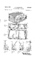
- Figure l is a perspective of the preferred form of follower as it appears when locked in place in a compartment taking the form of a drawer, parts of the drawer being broken away for convenience in illustration;
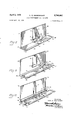
- Figures 2 and 3 are respectively a top plan and an elevation, both on an enlarged scale, of the follower of Figure 1 but with the operating lever in its unlocked position;
- Figures 4 and 5 are end elevations of the follower taken from the opposite ends thereof, the operating lever being" shown in its unlocked position;
- Figures 6 and 7 are corresponding end elevations of the follower with the operating lever in its locked position;
- Figures 8, 9 and 10 show three different modifications of the follower, each in perspec-' tive and as it appears when removed from the cornpartment.
- Compartment 1 is' of the sheet metal construction that is typical of the drawer of a filing cabinet, comprising, for example, a float meniber 2 a back member (not shown), a bottom member 3, and suitable side walls which extend between the front and back members and which rise from or impinge on bottom member 3 along the two long sides thereof.
- each of the two side walls consists of an outside wall portion 4 formed integrally with bottom member 3, a reversely bent top edge portion 5, and,- for strengthening and sliflening side wall portion 4, an inside filler 6 which terminates above bottom member 3 in order to form an elongated recess 7, which, as will appear, serves as one of two opposed ways for the slide forming part of the follower.
- the ways may, if desired, be differently formed; for example, if a wall of single rather than double thickness is used, each of the two ways may take the form of a channel-like groove in the material of which the Wall is made.
- the follower itself is likewise formed largely or entirely of sheet metal. It consists, along with other parts hereinafter described, of a long narrow base portion 8 running transversely of the longitudinal axis of the compartrnent which base portion is provided along its rear edge with an inturned integrally formed flange 9 and along its forward edge with an integrally formed upright body portion 11.
- base portion 8 and body portion 11 are produced from a single piece of sheet metal by stamping and bending them, base portion 8 and body portion 11 are offset from each other in the manner shown in Figure 1, from which it will be noted that far end 8a of base portion 8 projects beyond far edge 11a of body portion 11 into the way ⁇ fat the base of the far side wall of the compartment.
- the near end of base portion 8, designated 8b, is located some distance inwardly of the near edge 11b of body portion 11.
- Inturned flange 9 extends from the near end 8b of base portion 8 to a point near the opposite end thereof in alignment with the far edge 11a of body portion 11 thus terminating short of the far end 8a of base portion 8.
- Body portion 11 of the follower is intended to occupy' a position in which it is centered between the side walls of the compartment with appropriate clearance along its edges 11a and 1112. Therefore, base portion 8, being olfs'et therefrom, is necessarily laterally displaced relative to the longitudinal axis of bottom member 3 of the compartment 1. This is in order that the far end 8a of base portion 8 may coact with theway 7 at the base of the side wall on the far side of the" compartment as seeii in Figure 1. At the same time, on the near side of the compartment, space'for the near end of a slide is left between the end 812 of base portion 8' of the follower and the adjoining side wall.
- punch cards 12 Forward of body portion 11 are the punch cards 12, which, as indicated in Figure 1, may be packed or compressed without'substantial slack by bringing the follower into contact with them.
- punch cards In dealing with punch cards, it is advantageous to compress them in this manner for the reason that when so compressed they cannot warp during storage. It is difficult or impossible to put varped punch cards through the machines with which they are intended to be used. If desired, records of other types than punch cards may be stored in analogous fashion in compa'r'tmen 1.
- the hinge On the rearwardly facing side of body portion 11 is a hinge 13 provided with the usual hinge pin (not shown)".
- the hinge includes a stationary hinge leaf 14 fastened to body portion 11 by spot welding or otherwise, such stationary hinge leaf serving as a mounting strip for the hinge pin, the movable hinge leaf, and the parts associated with the movable hinge leaf.
- the lower edge of stationary hinge leaf 14 is disposed at short distance above base portion 8, just enough clearance being left between them to permit a slide to underlie and move freely beneath the lower edge of hinge leaf 14.
- the movable hinge leaf 15 is located above the axis of the hinge. To it is fastened, as by spot welding, the horizontal leg 15a of an L-shaped operating lever 16.
- Operating lever 16 is provided near the top of the upwardly extending leg 16!; thereof with a grasping portion 17. 7 When operating lever 16 is in vertical position, grasping portion 1'! projects upwardly above body portion 11 of the follower as shown in Figure 3.
- a slide actuator 18 which is more or less triangular in shape.
- Forming part of slide actuator 18 and depending from it at the lower end thereof is a generally square camming portion 19. The latter is angled as shown in Figures 2 and 3 and provided at the edge thereof nearest body portion 11 with an inwardly directed detent portion 19a.
- slide actuator 18 does not project perpendicularly to body portion 11 of the follower.
- camrning portion 19 may be properly located in the follower assembly, the main portion of slide actuator 18 departs from perpendicularity to body portion 11 in the manner and to the extent indicated.
- detent portion 19a is enabled to exercise a camming action when operating lever 16 is moved from the vertical position shown in Figures 2, 3, 4 and 5 to the inclined position shown in Figures 1, 6 and 7.
- This camming action is largely by virtue of the relationships which exist as between detent portion 19a and the coacting portions of the parts about to be described.
- slide 22 is provided with a downwardly reaching transverse shoulder 24. Extending therefrom is the near end 25 of slide 22, which cooperates with the way at the base of the adjoining side wall (not shown) in much. the same manner as does the far end 8a of base portion 8, which extends as described above into way 7.
- shoulder 24 is to offset near end 25 of slide 22 downwardly so that it can lie in substantially the same horizontal plane as far end 8a of base portion 8.
- slide 22 is provided with a circular opening 26 which loosely encompasses a hemi-spherical protuberance 27 extending upwardly from base portion 8 of the follower in the manner shown in Figures 1 and 2.
- the clearances along the sides of slide 22 are such that the slide can be introduced into the follower from the left-hand end thereof as seen in Figure l by urging it toward its intended position and permitting it to snap into place over the top of protuberance 27.
- opening 26 registers with protuberance 27, the slide as a whole drops sulficiently to permit protuberance 27 to act as a stop for the slide.
- opening 26 is of such size that appreciable lateral movement, perhaps as much in a typical case as one-eighth of an inch, is possible between base portion 8 and slide 22.
- Removal of the follower is accomplished by releasing operating lever 16, moving the slide or follower or both away from the side wallsof the compartment, and lifting the assembly out of the compartment, spreading the side walls slightly if required.
- the follower therein. shown has a laterally extending base portion 31.
- the far end 31a of the base leaving the near end unobstructed so as to permit it to enter into the way at the base of the side wall.
- Movably mounted on base portion 31 is a laterally extending slide 33 provided near its far end with a downwardly reaching shoulder 34 which serves to offset end portion 35 of slide 33 in such manner that it lies in substantially the same plane as near end 31]; of base portion 31 and, like
- both the follower as a whole and slide 22 may move simultathe latter, can co-act with the adjacent side wall of the compartment.
- Bracket-like element 36 Fastened by spot welding or otherwise to slide 33 is a bracket-like element 36 which, as shown in Figure 8, is of L-shaped configuration. It is made up of a horizontally extending portion 36:: and an upwardly extending lug-like portion 36b. The horizontally extending portion 36a is so located that its longitudinal axis is inclined at an angle of about to the longitudinal axis of slide 33.
- lug-like member 36b departs from perpendicularity to horizontally extending portion 36:: by an angle of about 10; that is to say, the dihedral angle b between horizontally extending portion 36a and upwardly extending portion 36b is approximately 80.
- a socketlike depression 37 Formed in any suitable manner in the outside or near face of lug-like member 36b, which face is produced when element 36 is bent to form dihedral angle 1), is a socketlike depression 37. The latter, together with the detent portion and other parts about to be described, provides a detent action between slide 33 and the actuator therefor.
- a more or less hemispherical protuberance 38 of slightly smaller diameter than socket-like depression 37 is formedin any convenient way on the far side of camming portion 39 of slide actuator 41.
- Camming portion 39 is so formed that it will parallel lug-like member 36b when the follower is locked in place in the compartment; in other words, at that time it makes an angle of about 10 to the longitudinal axis of slide 33 and an angle of about 80 to the plane of the slide.
- Slide actuator 41 of which camming portion 39 is an integral part, parallels the vertical plane including the longitudinal axis of the compartment. Slide actuator 41 itself forms an integral part of a movably mounted operating lever 42 located and mounted as shown in Figure 8.
- Operating lever 42 is attached by spot welding or otherwise to a movable hinge leaf 43.
- movable hinge leaf 43 Cooperating with movable hinge leaf 43 is a hinge pin (not shown) held in place by a stationary hinge leaf 44 that is spot welded or otherwise fastened to the upwardly extending body portion 45 of the follower.
- Stationary hinge leaf 44 is so located that slide 33 can move rather freely but without undue clearance beneath its lower edge.
- body portion 45 which is of course centered approximately midway between the side walls of the compartment when the follower is in use, is integral with base portion 31. The latter is offset from it for the same reasons and in the same manner as in the follower of Figures 1 to 7 inclusive.
- the follower shown in Figure 9 includes a laterally extending base portion 51. Both far end 51a and near end 51b appear in the drawing. Mounted by spot welding or otherwise on base portion 51 is a separate slide retainer 52, the same including a first laterally extending inturned flange 53 and, facing it, a second laterally extending inturned flange 54. Slide retainer 52 extends from far end 51a of base portion 51 to a point short of near end 51b, this so that near end 51b can co-act as previously described with the way at the base of the side wall of the compartment.
- a slide 55 mounted for lateral movement between flanges 53 and 54 of slide retainer 52 is a slide 55 provided with a shoulder 56 off-setting far end 57 thereof in the same manner and for the same purposes as those already described.
- a generally L-shaped bracket-like element 58 having a horizontally extending portion 58a and a vertically extending portion 58b. The latter thus constitutes a lug-like member projecting upwardly at right angles to the plane of slide 55.
- lug-like member 58b is cut away to produce the inclined surface 59, which defines an angle of about 20 to the vertical.
- surface 59 is interrupted as shown by a notch 61.
- Notch 61 is adapted to receive a ridge-like detent portion 62 forming part of camming portion 63 of slide actuator 64, which itself forms part of operating lever 65.
- the latter is fastened as by spot welding to a movable hinge leaf 66.
- Stationary hinge leaf 67 is fastened as byspot welding to body portion 68 of the follower.
- base portion 71 of the follower mounts a slide retainer 72 constructed similarly to the slide retainer 52 of the follower of Figure 9.
- a slide 73 co-acts with slide retainer 72.
- Mounted on slide 73 is an L-shaped bracketlike element 74 having a horizontally extending portion 740 and a vertically extending portion 74b.
- the forward edge of lug-like member 74b is interrupted by a notch 75 much as in the embodiment of the invention shown in Figure 9.
- notch 75 is positioned somewhat higher up; i. e., at a point farther removed from slide 73, than in the case of the corresponding notch in the lug-like member 58b forming part of the follower of Figure 9.
- aridge-like detent portion 76 forming part of the cumming portion 77 of a slide actuator 78.
- the latter is rigidly attached as by spot welding to body portion 79.
- the relationship between them is such that the rearwardly projecting portion of slide actuator 78 is perpendicular to body portion 79.
- Body portion 79 is hinged to base portion 71 by a hinge 80 of which the movable leaf 81 is spot welded or otherwise fastened to body portion 79 and stationary leaf 82 is spot welded or otherwise fastened to base portion 71.
- body portion 79 may be rotated through an angle totaling about movement in the rearward direction being limited to about 10 by engagement of slide actuator 78 with slide 73.
- the follower is designed for use with punch cards; in the form illustrated in Figure 10, the follower is designed for use with ordinary cards measuring 3" x 5" or 4" x 6", although it may, if desired, be used with punch cards, particularly if storage under compression is not a factor.
- part of the slide is engaged by part of the slide actuator, the engagement being usually (but not necessarily) between the slide actuator and a lug-like member on the slide.
- earning of the slide laterally of the follower is accomplished by means of the detent portion, which rides over an inclined surface on such luglike member. In doing so, it progressively urges the slide laterally of the follower.
- the detent portion lodges in a prepared position in which it is in engagement with a co-operating recess or portion on the lug-like member, thus providing the detent action to which reference has been made.
- the detent function is omitted, the camming will of course be done directly by the camming portion, which in such case will be in direct contact with the lug-like member on the slide.
- the invention provides an improved follower of the spreadable type which is of particularly simple construction.
- the follower is so designed that it can readily be inserted in or removed from the compartment. Once inserted, it can be located and relocated in the compartment and without requiring that slack be left in anticipation of its later relocation or removal.
- the locking device does not project into usable space in the compartment. It is not likely to become bent or warped in use, but if it does it can readily be straightened by application of a modicum of force. There are few or no parts that can get out of order. Together they make a strong, sturdy, rugged follower that will stand up over a long period of use.
- a filing compartment including a bottom portion, side walls impinging on the bottom portion, ways at the bottom of the side walls, and, engageable with said ways, a laterally spreadable follower consisting of a flat base portion characterized by an inturned flange at its rear edge, a flat body portion rigidly connected to the base portion at its forward edge, a mounting strip rigidly atlixed to the body portion above the base portion, an actuating lever hinged to the mounting strip for pivotal movement over the base portion, and, located in the path ofmovement ofand engageable by the actuating lever, a flat slide on the base portion one side of which slide underlies the mounting strip on the body portion of the follower and the other side of which slide underlies the inturned flange on the base portion, the plane of movement of the slide paralleling the plane, of said base portion;
- a filing compartment as in'claim l in which thetpart of the slide engageable by the slide actuating lever takes the form of a fiat lug-like member lying in a plane extending transversely of the longitudinal axis of the slide.
Landscapes
- Sheet Holders (AREA)
Description
April 1955 H. w. REGENHARDT FILE COMPARTMENT AND FOLLOWER 2 Sheets-Sheet 1 Filed April 13, 1955 Z3 /1NVENTOR.\ HANS W. REGENHARVT ATTORNEYS.
Apri 1956 H- w. REGENHARDT FILE COMPARTMENT AND FOLLOWER 2 Sheets-Sheet 2 Filed April 13, 1953 INVENTOR. HANS w. REGENHARUT W W, /Wmx//-(ZM ATTORNEYS.
United States Patent FlLE CQMPARTMENT AND FOLLOWER Hans W. Regenhardt, Wooster, Ohio, assignor to Record Files, Inc., Wooster, Ohio, a corporation of Ohio Application April 13, 1953, Serial No. 348,297
4 Claims. (Cl. 129-29) This invention relates to a filing compartment and follower permitting the material filed in the compartment; e. g., punch cards, to be packed in a manner leaving little or no slack forward of the follower.
With certain types of followers, it is necessary that slack be left forward of the follower when the latter is in position, this in order that the follower may be freed, preparatory to its relocation or removal, by moving it into the space so left. Such followers, which as a rule are of very simple construction, are useful where loss of space is not an important consideration; However, where space is at a premium, as in compartments for storing punch cards or other records that it is intended to preserve for long periods of time, it is desirable not only that the follower be of a kind permitting solid packing of the cards in the compartment but also that it be of a kind requiring a minimum of space in and of itself. A major object of the invention is to provide a spreadable follower satisfying both of these desiderata.
Another object of the invention is the provision of a follower embodying an improved locking device for fixing the follower firmly in the desired position in the compartment. Another object of the inventionis to provide such a follower and locking device which may be manufactured easily and inexpensively but which have ample sturdiness required to resist the forces likely to be imposed upon them. Still another object of the invention is to provide a follower and locking device which can be readily installed in, relocated, or removed from a filing compartment of the kind provided with ways extending longitudinally of the side walls of the compartment.
Additional objects and advantages of the invention will become apparent from the following description. of several differently constructed followers and from the accompanying drawings, in which Figure l is a perspective of the preferred form of follower as it appears when locked in place in a compartment taking the form of a drawer, parts of the drawer being broken away for convenience in illustration; Figures 2 and 3 are respectively a top plan and an elevation, both on an enlarged scale, of the follower of Figure 1 but with the operating lever in its unlocked position; Figures 4 and 5 are end elevations of the follower taken from the opposite ends thereof, the operating lever being" shown in its unlocked position; Figures 6 and 7 are corresponding end elevations of the follower with the operating lever in its locked position; and Figures 8, 9 and 10 show three different modifications of the follower, each in perspec-' tive and as it appears when removed from the cornpartment.
In such drawings, the preferred form of follower is shown first as it appears when locked in place in the compartment of Figure 1. Compartment 1 is' of the sheet metal construction that is typical of the drawer of a filing cabinet, comprising, for example, a float meniber 2 a back member (not shown), a bottom member 3, and suitable side walls which extend between the front and back members and which rise from or impinge on bottom member 3 along the two long sides thereof. In the particular construction shown, each of the two side walls consists of an outside wall portion 4 formed integrally with bottom member 3, a reversely bent top edge portion 5, and,- for strengthening and sliflening side wall portion 4, an inside filler 6 which terminates above bottom member 3 in order to form an elongated recess 7, which, as will appear, serves as one of two opposed ways for the slide forming part of the follower. The ways may, if desired, be differently formed; for example, if a wall of single rather than double thickness is used, each of the two ways may take the form of a channel-like groove in the material of which the Wall is made.
All of the component parts so far described are of sheet metal and fastened together as by spot-welding to provide a drawer of unitary construction.
The follower itself is likewise formed largely or entirely of sheet metal. It consists, along with other parts hereinafter described, of a long narrow base portion 8 running transversely of the longitudinal axis of the compartrnent which base portion is provided along its rear edge with an inturned integrally formed flange 9 and along its forward edge with an integrally formed upright body portion 11. Although base portion 8 and body portion 11 are produced from a single piece of sheet metal by stamping and bending them, base portion 8 and body portion 11 are offset from each other in the manner shown inFigure 1, from which it will be noted that far end 8a of base portion 8 projects beyond far edge 11a of body portion 11 into the way {fat the base of the far side wall of the compartment. The near end of base portion 8, designated 8b, is located some distance inwardly of the near edge 11b of body portion 11. Inturned flange 9 extends from the near end 8b of base portion 8 to a point near the opposite end thereof in alignment with the far edge 11a of body portion 11 thus terminating short of the far end 8a of base portion 8.
7 Forward of body portion 11 are the punch cards 12, which, as indicated in Figure 1, may be packed or compressed without'substantial slack by bringing the follower into contact with them. In dealing with punch cards, it is advantageous to compress them in this manner for the reason that when so compressed they cannot warp during storage. It is difficult or impossible to put varped punch cards through the machines with which they are intended to be used. If desired, records of other types than punch cards may be stored in analogous fashion in compa'r'tmen 1.
On the rearwardly facing side of body portion 11 is a hinge 13 provided with the usual hinge pin (not shown)". The hinge includes a stationary hinge leaf 14 fastened to body portion 11 by spot welding or otherwise, such stationary hinge leaf serving as a mounting strip for the hinge pin, the movable hinge leaf, and the parts associated with the movable hinge leaf. The lower edge of stationary hinge leaf 14 is disposed at short distance above base portion 8, just enough clearance being left between them to permit a slide to underlie and move freely beneath the lower edge of hinge leaf 14. The movable hinge leaf 15 is located above the axis of the hinge. To it is fastened, as by spot welding, the horizontal leg 15a of an L-shaped operating lever 16.
In Figure 1, all parts of the follower appear in the position which they occupy when the follower is locked in place. in Figures 2 and 3 the follower is shown as it appears immediately after the operating lever has been moved from its inclined to its upright position. Apart from the operating lever, the other parts, including certain parts yet to be described, are shown in Figures 2 and 3 as remaining in the positions which they assumed when the follower was first locked in place. Thus in Figure 3 the far end 8a of base portion 8 is shown in contact with side wall portion 4; i. e., as projecting into way 7 at the base of the side wall.
As shown in Figures 2 and 3, slide actuator 18 does not project perpendicularly to body portion 11 of the follower. In order that camrning portion 19 may be properly located in the follower assembly, the main portion of slide actuator 18 departs from perpendicularity to body portion 11 in the manner and to the extent indicated. As a result, detent portion 19a is enabled to exercise a camming action when operating lever 16 is moved from the vertical position shown in Figures 2, 3, 4 and 5 to the inclined position shown in Figures 1, 6 and 7. This camming action is largely by virtue of the relationships which exist as between detent portion 19a and the coacting portions of the parts about to be described.
Paralleling the plane of camming portion 19 when the follower is in the position shown in Figure l is .a flat lug 21 upstanding in such manner as to form therewith a dihedral angle a of about 80 (Figure 3) at one end of a laterally extending slide 22. The slide 22, best seen in Figure l, is in movable contact with base portion 8,
being held in place by the'retaining'means formed by stationary hinge leaf 14 and the inturned flange 9 on base portion 8, both of which overlie the edges of the slide in such manner as to permit movement laterally of the follower but no appreciable movement at right angles thereto; i. e., in the direction of the longitudinal axis of the compartment. As shown in Figure 2, the far end 23 of slide 22, of which lug 21 is an integral part and from which lug 21 projects upward into the path of movement of detent portion 19a, is slanted at an angle of about 10 to the horizontal trace of the vertical plane including the longitudinal axis of the compartment. 'As a result, the horizontal trace of the plane of lug 21 likewise makes an angle of about 10 therewith, such angle being independent of the above-described dihedral angle a, which, as stated, measures about 80.
When operating lever 16 is in the depressed position shown in Figure 1, detent portion 19a of camming portion 19 engages the upright inner edge of lug 21 as shown in Figure 6, the resulting detent action holding the operating lever firmly in place.
At the opposite end of slide 22, that is to say, the end which projects outwardly from nearend 8b of base portion 8, slide 22 is provided with a downwardly reaching transverse shoulder 24. Extending therefrom is the near end 25 of slide 22, which cooperates with the way at the base of the adjoining side wall (not shown) in much. the same manner as does the far end 8a of base portion 8, which extends as described above into way 7. 'The purpose of shoulder 24 is to offset near end 25 of slide 22 downwardly so that it can lie in substantially the same horizontal plane as far end 8a of base portion 8. Thus the two opposite ends of the follower can co-act simultaneously with the ways formed where the side walls of the compartment impinge on bottom member 3.
To retain slide 22 and base portion 8 in the desired relation and prevent them from coming apart when removed from the drawer whilestill permitting limited relative movement between them, slide 22 is provided with a circular opening 26 which loosely encompasses a hemi-spherical protuberance 27 extending upwardly from base portion 8 of the follower in the manner shown in Figures 1 and 2. The clearances along the sides of slide 22 are such that the slide can be introduced into the follower from the left-hand end thereof as seen in Figure l by urging it toward its intended position and permitting it to snap into place over the top of protuberance 27. After opening 26 registers with protuberance 27, the slide as a whole drops sulficiently to permit protuberance 27 to act as a stop for the slide. In relation to the diameter of protuberance 27, opening 26 is of such size that appreciable lateral movement, perhaps as much in a typical case as one-eighth of an inch, is possible between base portion 8 and slide 22.
Such movement is of course relative in the sense that either or both of base portion 8 and slide 22 may move or be moved incident to the operations of inserting, re moving or operating the follower. Actually, either or both may move relative to the compartment when the follower is locked in place. If, for example, the follower as a whole is inserted from the left-hand side of the compartment as seen in Figure 1, far end 8a of base portion 8 will normally be inserted in way 7 when the follower is introduced into the compartment, after which slide 22 will be moved by means of operating lever 16. If, however, near end 25 of slide 22 is inserted into the way of the base of the adjoining side wall, the follower as a whole (exclusive of slide 22) will move toward the opposite side wall when operating lever 16 is moved from the upright position of Figures 2 and 3 into the depressed position of Figure l.
neously in opposite directions. Removal of the follower is accomplished by releasing operating lever 16, moving the slide or follower or both away from the side wallsof the compartment, and lifting the assembly out of the compartment, spreading the side walls slightly if required.
Referring now to the form of the invention illustrated in Figure 8, the follower therein. shown has a laterally extending base portion 31. The far end 31a of the base leaving the near end unobstructed so as to permit it to enter into the way at the base of the side wall. Movably mounted on base portion 31 is a laterally extending slide 33 provided near its far end with a downwardly reaching shoulder 34 which serves to offset end portion 35 of slide 33 in such manner that it lies in substantially the same plane as near end 31]; of base portion 31 and, like In some circumstances, both the follower as a whole and slide 22 may move simultathe latter, can co-act with the adjacent side wall of the compartment.
Fastened by spot welding or otherwise to slide 33 is a bracket-like element 36 which, as shown in Figure 8, is of L-shaped configuration. It is made up of a horizontally extending portion 36:: and an upwardly extending lug-like portion 36b. The horizontally extending portion 36a is so located that its longitudinal axis is inclined at an angle of about to the longitudinal axis of slide 33. In addition to having a degree of cant transversely of the longitudinal axis of slide 33 which is complementary to the angle of inclination of the longitudinal axis of horizontal portion 36a, lug-like member 36b departs from perpendicularity to horizontally extending portion 36:: by an angle of about 10; that is to say, the dihedral angle b between horizontally extending portion 36a and upwardly extending portion 36b is approximately 80. Formed in any suitable manner in the outside or near face of lug-like member 36b, which face is produced when element 36 is bent to form dihedral angle 1), is a socketlike depression 37. The latter, together with the detent portion and other parts about to be described, provides a detent action between slide 33 and the actuator therefor.
To make possible this detent function, a more or less hemispherical protuberance 38 of slightly smaller diameter than socket-like depression 37 is formedin any convenient way on the far side of camming portion 39 of slide actuator 41. Camming portion 39 is so formed that it will parallel lug-like member 36b when the follower is locked in place in the compartment; in other words, at that time it makes an angle of about 10 to the longitudinal axis of slide 33 and an angle of about 80 to the plane of the slide. Slide actuator 41, of which camming portion 39 is an integral part, parallels the vertical plane including the longitudinal axis of the compartment. Slide actuator 41 itself forms an integral part of a movably mounted operating lever 42 located and mounted as shown in Figure 8.
Operating lever 42 is attached by spot welding or otherwise to a movable hinge leaf 43. Cooperating with movable hinge leaf 43 is a hinge pin (not shown) held in place by a stationary hinge leaf 44 that is spot welded or otherwise fastened to the upwardly extending body portion 45 of the follower. Stationary hinge leaf 44 is so located that slide 33 can move rather freely but without undue clearance beneath its lower edge. Like flange 32, it constitutes part of the means for retaining slide 33 in the follower assembly. Body portion 45, which is of course centered approximately midway between the side walls of the compartment when the follower is in use, is integral with base portion 31. The latter is offset from it for the same reasons and in the same manner as in the follower of Figures 1 to 7 inclusive.
The follower shown in Figure 9 includes a laterally extending base portion 51. Both far end 51a and near end 51b appear in the drawing. Mounted by spot welding or otherwise on base portion 51 is a separate slide retainer 52, the same including a first laterally extending inturned flange 53 and, facing it, a second laterally extending inturned flange 54. Slide retainer 52 extends from far end 51a of base portion 51 to a point short of near end 51b, this so that near end 51b can co-act as previously described with the way at the base of the side wall of the compartment.
Mounted for lateral movement between flanges 53 and 54 of slide retainer 52 is a slide 55 provided with a shoulder 56 off-setting far end 57 thereof in the same manner and for the same purposes as those already described. Mounted on slide 55 is a generally L-shaped bracket-like element 58 having a horizontally extending portion 58a and a vertically extending portion 58b. The latter thus constitutes a lug-like member projecting upwardly at right angles to the plane of slide 55. Along its near edge, lug-like member 58b is cut away to produce the inclined surface 59, which defines an angle of about 20 to the vertical. In or'def' to provide a detent action, surface 59 is interrupted as shown by a notch 61.
Notch 61 is adapted to receive a ridge-like detent portion 62 forming part of camming portion 63 of slide actuator 64, which itself forms part of operating lever 65. The latter is fastened as by spot welding to a movable hinge leaf 66. Stationary hinge leaf 67 is fastened as byspot welding to body portion 68 of the follower. When the follower is locked in position in the compartment, operating lever 65, slide actuator 64 and camming portion 63 occupy a depressed position in which detent portion 62 of camming portion 63 enters into notch 61 in inclined surface 59 of lug-like member 58b. In general, the plane of cumming portion 63 is so angled as to parallel surface 59 when the follower is locked in position. Slide actuator 64 extends perpendicularly to the main portion of operating lever as shown.
In the further form of the invention shown in Figure 10, base portion 71 of the follower mounts a slide retainer 72 constructed similarly to the slide retainer 52 of the follower of Figure 9. A slide 73 co-acts with slide retainer 72. Mounted on slide 73 is an L-shaped bracketlike element 74 having a horizontally extending portion 740 and a vertically extending portion 74b. The forward edge of lug-like member 74b is interrupted by a notch 75 much as in the embodiment of the invention shown in Figure 9. However, notch 75 is positioned somewhat higher up; i. e., at a point farther removed from slide 73, than in the case of the corresponding notch in the lug-like member 58b forming part of the follower of Figure 9.
Co-acting therewith is aridge-like detent portion 76 forming part of the cumming portion 77 of a slide actuator 78. The latter is rigidly attached as by spot welding to body portion 79. The relationship between them is such that the rearwardly projecting portion of slide actuator 78 is perpendicular to body portion 79. Body portion 79 is hinged to base portion 71 by a hinge 80 of which the movable leaf 81 is spot welded or otherwise fastened to body portion 79 and stationary leaf 82 is spot welded or otherwise fastened to base portion 71. By virtue of this arrangement of parts, body portion 79 may be rotated through an angle totaling about movement in the rearward direction being limited to about 10 by engagement of slide actuator 78 with slide 73.
In the forms of the invention illustrated in Figures 1 to 9, the follower is designed for use with punch cards; in the form illustrated in Figure 10, the follower is designed for use with ordinary cards measuring 3" x 5" or 4" x 6", although it may, if desired, be used with punch cards, particularly if storage under compression is not a factor. v
In all four forms of the invention, part of the slide is engaged by part of the slide actuator, the engagement being usually (but not necessarily) between the slide actuator and a lug-like member on the slide. In these forms of the invention, earning of the slide laterally of the follower is accomplished by means of the detent portion, which rides over an inclined surface on such luglike member. In doing so, it progressively urges the slide laterally of the follower. When the slide actuator has been moved from its upright to its depressed position, the detent portion lodges in a prepared position in which it is in engagement with a co-operating recess or portion on the lug-like member, thus providing the detent action to which reference has been made. If, as may be desired in some circumstances, the detent function is omitted, the camming will of course be done directly by the camming portion, which in such case will be in direct contact with the lug-like member on the slide.
Thus the invention provides an improved follower of the spreadable type which is of particularly simple construction. The follower is so designed that it can readily be inserted in or removed from the compartment. Once inserted, it can be located and relocated in the compartment and without requiring that slack be left in anticipation of its later relocation or removal. The locking device does not project into usable space in the compartment. It is not likely to become bent or warped in use, but if it does it can readily be straightened by application of a modicum of force. There are few or no parts that can get out of order. Together they make a strong, sturdy, rugged follower that will stand up over a long period of use.
Changes and modifications may be made without departing from the spirit or scope of the invention. it is therefore to be understood that the patent is not limited to the four preferred forms of invention. On the contrary, it is intended that the patent shall cover, by summarization in the appended claims, all features of patentable novelty residing in the invention.
What is claimed is:
l. A filing compartment including a bottom portion, side walls impinging on the bottom portion, ways at the bottom of the side walls, and, engageable with said ways, a laterally spreadable follower consisting of a flat base portion characterized by an inturned flange at its rear edge, a flat body portion rigidly connected to the base portion at its forward edge, a mounting strip rigidly atlixed to the body portion above the base portion, an actuating lever hinged to the mounting strip for pivotal movement over the base portion, and, located in the path ofmovement ofand engageable by the actuating lever, a flat slide on the base portion one side of which slide underlies the mounting strip on the body portion of the follower and the other side of which slide underlies the inturned flange on the base portion, the plane of movement of the slide paralleling the plane, of said base portion; i
2. A filing compartment as in claim '1 in which the part of the slide engageable by the slide actuating lever is provided with aportion serving as a detent.
3. A filing compartment as in claim 1 in which the part of the slide'engageable by the slide actuating lever takes the form of an upwardly projecting lug-like member.
4. A filing compartment as in'claim l in which thetpart of the slide engageable by the slide actuating lever takes the form of a fiat lug-like member lying in a plane extending transversely of the longitudinal axis of the slide.
References Citedin the file of this patent UNITED STATES PATENTS 304,627 Du Bois Sept. 2, 1884 927,303 Walton July 6, 1909 990,319 Walton u Apr. 25, 1911 1,044,032 Dunleavy Nov. 12, 1912 2,163,319 Gerkey June 20, 1939
Priority Applications (1)
| Application Number | Priority Date | Filing Date | Title |
|---|---|---|---|
| US348297A US2740407A (en) | 1953-04-13 | 1953-04-13 | File compartment and follower |
Applications Claiming Priority (1)
| Application Number | Priority Date | Filing Date | Title |
|---|---|---|---|
| US348297A US2740407A (en) | 1953-04-13 | 1953-04-13 | File compartment and follower |
Publications (1)
| Publication Number | Publication Date |
|---|---|
| US2740407A true US2740407A (en) | 1956-04-03 |
Family
ID=23367407
Family Applications (1)
| Application Number | Title | Priority Date | Filing Date |
|---|---|---|---|
| US348297A Expired - Lifetime US2740407A (en) | 1953-04-13 | 1953-04-13 | File compartment and follower |
Country Status (1)
| Country | Link |
|---|---|
| US (1) | US2740407A (en) |
Cited By (2)
| Publication number | Priority date | Publication date | Assignee | Title |
|---|---|---|---|---|
| US3250276A (en) * | 1962-05-16 | 1966-05-10 | Hamilton Skotch Corp | File box or container |
| US5054853A (en) * | 1988-03-18 | 1991-10-08 | John D. Gillies | Infant safety chairs |
Citations (5)
| Publication number | Priority date | Publication date | Assignee | Title |
|---|---|---|---|---|
| US304627A (en) * | 1884-09-02 | du bois | ||
| US927303A (en) * | 1908-09-19 | 1909-07-06 | Unit Steel Cabinet Company | Card-file. |
| US990319A (en) * | 1910-07-29 | 1911-04-25 | Unit Steel Cabinet Company | Follower structure for record-receptacles. |
| US1044032A (en) * | 1912-09-06 | 1912-11-12 | James Frank Dunleavy | Filing-case. |
| US2163319A (en) * | 1937-09-27 | 1939-06-20 | William M Gerkey | Follower for card files |
-
1953
- 1953-04-13 US US348297A patent/US2740407A/en not_active Expired - Lifetime
Patent Citations (5)
| Publication number | Priority date | Publication date | Assignee | Title |
|---|---|---|---|---|
| US304627A (en) * | 1884-09-02 | du bois | ||
| US927303A (en) * | 1908-09-19 | 1909-07-06 | Unit Steel Cabinet Company | Card-file. |
| US990319A (en) * | 1910-07-29 | 1911-04-25 | Unit Steel Cabinet Company | Follower structure for record-receptacles. |
| US1044032A (en) * | 1912-09-06 | 1912-11-12 | James Frank Dunleavy | Filing-case. |
| US2163319A (en) * | 1937-09-27 | 1939-06-20 | William M Gerkey | Follower for card files |
Cited By (2)
| Publication number | Priority date | Publication date | Assignee | Title |
|---|---|---|---|---|
| US3250276A (en) * | 1962-05-16 | 1966-05-10 | Hamilton Skotch Corp | File box or container |
| US5054853A (en) * | 1988-03-18 | 1991-10-08 | John D. Gillies | Infant safety chairs |
Similar Documents
| Publication | Publication Date | Title |
|---|---|---|
| US3814490A (en) | File drawer follower block | |
| US3854785A (en) | Actuating device | |
| US3404929A (en) | Interlocking of selected units of a storage system | |
| US3923347A (en) | Suspension latch | |
| US4081100A (en) | Spring-loaded drawer partition | |
| US3679274A (en) | Broiler drawer and slide | |
| US2812222A (en) | Permanent ball retainer for sliding members | |
| US5151847A (en) | Device for electrically contacting an electronic apparatus with an ic-memory card | |
| US2740407A (en) | File compartment and follower | |
| KR850002148A (en) | Storage container for compact cassette | |
| US2746457A (en) | Universal follow up compressor | |
| US3127022A (en) | Adjustable shelf partition | |
| US3107816A (en) | Record storage and dispensing device | |
| US1231154A (en) | Follower-block for filing-cases. | |
| US3687326A (en) | Followers for filing units | |
| US3658185A (en) | Storage and retrieval device | |
| JPH05504099A (en) | document punch | |
| US2523722A (en) | Index rod for filing cabinets | |
| US3718232A (en) | File tray control plate system | |
| US4600247A (en) | Housing with a dust cover having a pivoted front | |
| US3533532A (en) | Follower for card tray | |
| US2906269A (en) | Followers for filing cabinets | |
| US2648337A (en) | File compressor | |
| US3517854A (en) | Spring biased follower | |
| US2682966A (en) | Sheet metal file |