US2694271A - Animated trackside accessory for toy railroads - Google Patents
Animated trackside accessory for toy railroads Download PDFInfo
- Publication number
- US2694271A US2694271A US152554A US15255450A US2694271A US 2694271 A US2694271 A US 2694271A US 152554 A US152554 A US 152554A US 15255450 A US15255450 A US 15255450A US 2694271 A US2694271 A US 2694271A
- Authority
- US
- United States
- Prior art keywords
- platform
- toy
- motor
- switch
- animated
- Prior art date
- Legal status (The legal status is an assumption and is not a legal conclusion. Google has not performed a legal analysis and makes no representation as to the accuracy of the status listed.)
- Expired - Lifetime
Links
- 230000033001 locomotion Effects 0.000 description 14
- 238000005406 washing Methods 0.000 description 9
- 238000004804 winding Methods 0.000 description 6
- 230000000994 depressogenic effect Effects 0.000 description 4
- 238000004140 cleaning Methods 0.000 description 3
- 238000010586 diagram Methods 0.000 description 3
- 241000404158 Lonas Species 0.000 description 1
- 230000008933 bodily movement Effects 0.000 description 1
- 238000010276 construction Methods 0.000 description 1
- 230000008878 coupling Effects 0.000 description 1
- 238000010168 coupling process Methods 0.000 description 1
- 238000005859 coupling reaction Methods 0.000 description 1
- 230000000694 effects Effects 0.000 description 1
- 239000000463 material Substances 0.000 description 1
- 239000002184 metal Substances 0.000 description 1
- 230000000149 penetrating effect Effects 0.000 description 1
- 230000000750 progressive effect Effects 0.000 description 1
- 230000003252 repetitive effect Effects 0.000 description 1
- 230000000284 resting effect Effects 0.000 description 1
- 230000002441 reversible effect Effects 0.000 description 1
- 238000005096 rolling process Methods 0.000 description 1
- XLYOFNOQVPJJNP-UHFFFAOYSA-N water Substances O XLYOFNOQVPJJNP-UHFFFAOYSA-N 0.000 description 1
Images
Classifications
-
- A—HUMAN NECESSITIES
- A63—SPORTS; GAMES; AMUSEMENTS
- A63H—TOYS, e.g. TOPS, DOLLS, HOOPS OR BUILDING BLOCKS
- A63H19/00—Model railways
- A63H19/34—Bridges; Stations; Signalling systems
Definitions
- This invention relates to animated track side accessories for toy railroads designed to simulate realistically actual operations familiar in the use and servicing of toy trains.
- An object of the present improvements is to animate the gurette of a window washer so that he shall appear to go through the motions of washing the windows of a toy railway car.
- a related object is to provide, in form to be merchandised as a self-operative, unitary toy railway trackside accessory, a motor equipped trackside platform along which the ligurette will advance or make excursions in realistic manner against the outside of the windows of a toy railway car standing on its tracks.
- Another object is to produce animation in such a toy so quietly that mechanical noise shall not impair the illusion of an actual train window washer at work.
- Another object is to produce the illusion of window washing in miniature form with the fewest and simplest possible number of movable parts of rugged nature able to withstand abuse as a plaything without breakage and czfrpable of selling in the low range of price demanded o toys.
- Another object is to effect automatic stopping of the progressive travel of the toy ligure along the trackside platform when the length of the toy railway car has been traversed.
- a related objected is to cause reversal of the direction of travel of the toy ligure along the platform at one or both ends of its range of travel so that the figure will perform automatically one or more excursions alongside the toy car without further attention when once set in action.
- a still further object is to conceal the power means by which the toy is animated so that realism of the action of the irnitative workman is enhanced.
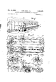
- Fig. 1 is an overall view in perspective showing the trackside accessory properly placed in relation to the passenger car and tracks of a toy railway.
- Fig. 2 is a plan View of the accessory unit alone showing the imitative tool box removed from the platform to expose the motor which anirnates the toy.
- Fig. 3 is a bottom plan view showing the motiontransmitting mechanism inside the hollow platform.
- Fig. 4 is a view taken in section on the plane 4 4 in .Fig 2 looking in the direction of-the arrows.
- Fig. 5 is a-view taken in section on the plane 5 5 in Fig. 2 looking in the direction of the arrows.
- Fig. 6 is a view taken in section on the plane 6 6 in Fig. 2 looking in the direction of the arrows.
- Fig. 7 is a fragmentary view taken on the plane 7 7 in Fig. 2 looking in the direction of the arrows.
- Fig. 8 is an enlarged fragmentary view taken in section on the plane 8 8 in Fig. 6.
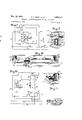
- Fig. 9 is a diagram of electric circuit connections suitable for use with the structure of Fig. 3.
- Fig. l0 is a view like Fig. 3 showing a modified form of circuit controlling mechanism acting automatically to stop running of the toy animating motor at predetermined limits in the course of travel of the window washing figure.
- Fig. 11 shows one circuit controller of Fig. 10 when automatically acted upon to break the motor circuit.
- Fig. l2 is a diagram ⁇ of mod ilied circuitconnections suitable for use with the structure of Fig. 10.
- the conventional toy passenger c ar 10 of a toy railway train stands motionless on tracks 11 of a ktoy railroad resting on, say, a table top 13.
- the trackside accessory unit embodying the .present improvements includes a hollow elongated platform 12 which may be placed on such .tabletopalongside the rolling stock of a toy train such as the passenger car 10.
- the figurette 14 of a car servicing workman or window washer' is integral ⁇ with a slidable base plate 15 on which is fixed an imitative water pail 16.
- Base 15 is slidable lengthwise along the top surface of the floor wall 31 of platform 12 and is motivated by a traveling nut 17 which has threaded engagement with and rides along a power operated screw shaft 23 in the hollow interior of platform 12.
- Nut 17 includes a horizontal llange .18 closely underlying theoor wall 31 of the platform which flange is made fast to base 1 5 of the man ligure by a Connecting stud 22 rigid with pail 16 extending through and havinga sliding tit in slot 21 ofA platform floor 31 and havingthreaded engagement with flange 18 so as to hold base plate 15 and said flange in fixed relation vertically spaced apart far enough to afford free but steadying engagement of the figure base plate 15 with the top surface of ⁇ the platform.
- flange 18 For added steadying connection betweenbaseplate 15 and nut, flange 18 the former fixedly carriesa depending lug 20 ,penetrating the latter.
- Screw shaft 23 has ends of. reduced diameter which have rotary bearing in brackets 24 and 25 respectively. These brackets aresecured to the platform 12 by screws 26 and afford end thrust in both directions for the screw shaft 23.
- a f i On one of its ends screw rod 23 iXedly carries a ⁇ driven worm gear 29 which is constantly inmesh with the driving worm 30 cut on or carried by armature shaft 35. of a conventional reversable electric motor 32.
- Motor 32 is preferably mounted atop the platform floor wall 3 1 asby screws 33 and is concealed by Aa hollow housing structure 34 imitative of a tool box such as commonly stands in handy locations on railway platforms forstoring train servicingequipment.
- Motor shaft 35 extends dowziigvard into the hollow platform 12 through an opening
- the brush handle reciprocates loosely through an oversize hole 39 in'base plate 15 of the figurette as bestshown in Fig. 7, and its bottom end 4 7 is looped to ⁇ engage'swingably the -elongated 'actuating span 41 of Va bail crank 42 whose ends 43 are journaled in bearings 44 on the end walls 45 of platform 12.
- An offset jog 49 in bail span 41 is raisable and allowed to lower'alternately ⁇ by the oscillating movements ofa stiff arm 50 which may be made of strip metal having a of the platform there takes place simultaneously up-and- 50 l 'quarter-turntwist.
- Arm 50 is pivotallymounted'for free swinging movementon a screw stud 5 1 ,carried by'an angle bracket 52 fixed'atop the platform oor wall 31 at the side of aperture36'in the latter.
- Worm gear 29 carries arevolvable c ra'nkpin 53 in whose path ofcircular travel the freely swingable arm 50 falls.
- the traveling nut 17 carriesfxedthereo'n theinsulatiye frame 56 of a motor reversing erating handle 58 is guided by the switch frame 5 6 for lengthwise horizontal reciprocatory movement -relative thereto.
- Handle 58 carriesa contact actuating spur 59 which in passing the conductive contact platek 60 ofthe switch depresses vthe latter edgewisein a direction to compress the frame nested spring 61.
- This spring causes c ontact plate 60 to flip with a snap motion between two-circuit controlling positions when the tip of spur 5 9 passes'vr it. In one of these positions contact 60 vconductively bridges' two circuit terminals 62,63. In the other of saidpositions it conductively bridges two other circuit terminals 64, 65.
- the oppositeends of switch handle 58 project'horizontally aes-1,271
- Fig. 9 shows a scheme of circuit connections enabling the form of the toy shown in Figs. l to 8 to continue to function automatically when once put into action.
- Those elements represented in Fig. 9 which are disclosed in Figs. 1 to 8 are denoted respectively by like numerals.
- the field Winding 66 of the reverslng motor 32 supplied at a mean point from one side 67 of the supply line through lead 68.
- This supply line may be opened and closed at will to stop and start animatlon of the toy by throwing a manual remote control sw1tch68 which may be located anywhere the operator of the railway system desires;
- the other side 70 of the supply 1s connected through lead 71 to one brush of the motor.
- the other motor brush connects with both of circuit terminals 62 and 64 of switch 57 through leads 72 and 73, respectively.
- One extremity of motor winding 66 connects to circuit terminal 63 of the switch by means of lead 74
- the motor winding opposite extremity connects to circuit terminal 65 of the switch by means of lead 75.
- All of leads 72, 73, 74 and 75 will be flexible and preferably shall be harnessed in a unitary exible cable (not shown) as they must be able to trail the bodily movement of switch 57 in unison with nut 17 lengthwise of the platform.
- Figs.v 10 to 1 2 there is shown a modified form of the invention wherein it is not necessary that the motor reversing switch be mounted to travel in unison with the iigurette.
- the traveling nut 17 carries fixed thereon only a double ended thrust bar 78 of insulative material.
- this thrust bar is seen to have arrived at a position at the right end of its travel wherein it has pushed against a conductive spring leaf contact 79 that normally lies in circuit-making engagement with a companion contact 80 so that contact 78 is caused to separate from contact 80 breaking the circuit to motor 32 therethrough.
- Contacts 79 and 80 are mounted on the rear upright wall 81 of platform 12 in insulated relation thereto and to each -other ⁇ The same is true of another pair of like contacts 82, 8 3 in Fig. l0, stationed near the opposite end of the travel of thrust bar 78.
- FIG. 12 denotes the above mentioned .mechanical parts by like reference numerals.k
- this diagram shows a ⁇ remotely located double push button control station at which there is one ⁇ normally open remote control push button switch 84 which serves when manually depressed to energize only the piatform carried contact 80 through a lead 85 from line 67 while another normally open remote control push button switch 86serves when manually depressed to energize only 'the platform carried contact 82 through lead 87.
- the lother platform carried contacts 79 and 83 connect toV oppositel extremities of the motor field winding 66 through leads S3 and 89 respectively.
- a mean point infield winding-66 connects through the armature of the motor to'power line 70 through the lead 9i) which for convenience o'f wiring passes through the remote control box 91 containing the remote control switches 84 and S6.
- lf remotelcontrol switch 84 is held closed longer than required to advance the iigurette to the limit of its travel toward the right, no damage will be done by continued attempt of motor 32 to run because the motor circuit then' automatically becomes broken at contacts 79, Sti when these contacts are forced to separate' by the travel of thrust bar 78.
- the motor can then be restarted only in an opposite direction ofrunning and this is done by manually closing remote 'control switch 86.
- This switch may be held Vclosed yr'nanually until lthe figurette has completed its travel along the platform whereupon platform carried contacts 82. 83 will again become automatically opened by the opposite end of thrust bar 7 8.
- both pairs vof contacts 82, 83 and 79, 80 will be closed, making it possible at will to start the iourney o'f'the window washer in either direction depending u'pon which of the remote control switch buttons 84 or S6 is manually depressed.
- An animated trackside accessory for toy railroads embodying in combination, an elongated hollow'structure 'fashioned to represent a station platform adapted to be placed alongside a toy railway track, said platform4 having van elevated floor wall containing a slot eX- tendinglengthwise thereof.
- Va iizurette having an impellable projection extending 'through saidv slot and fashioned tor represent a Window washer standing atop said platform.
- a reciprocative element fashioned to represent a window washing brush having a long straight handle guided bysaid'figuret't'e for lengthwise movement and extending through 'said slot.
- said animating mechanism Vat least in part beneath said floor wall including connections' to said impellable projection constructed and arranged to 'causesaidftigurettetto'heimpelled along said platform structure'bymeans of said projection.
- said animating mechanism also including connections to said reciprocative' element exclusive' "of said tigurette constructed ⁇ and arranged tov reciprocate said element lonas defined in claim 1, in which the said animating mechanism includes a prime mover so operatively and impellingly related to both the said gurette impelling projection and the said reciprocative element that bodily travel of said gurette and window washing movement of the said brush representing element occur simultaneously.
- An animated toy for simulating the operation of a window washing workman comprising in combination, a pseudo window cleaning appliance including an upright rod simulating a reach extending handle of said appliance, a gurette having a foot portion and having a trunk portion with integral arm and hand portions in xed relation thereto, a slide bearing comprising an opening through at least one of said hands of the iigurette through which opening said rod slidably extends, a source of animating motion, connections exclusive of the trunk arm and hand portions of the tgurette including a rocker pivotally connected to said rod and operatively coupling said rod to said source of motion in a manner to cause said rod to be reciprocated lengthwise upward and downward through said bearing relatively to said gurette, a floor beneath said igurette comprising a straight guideway extending in sidewise direction relatively to the gurette slidably engaged by said foot portion thereof, and movement transmitting means including a screw thread follower joined to the said iigurette and a rotatable screw thread
Landscapes
- Toys (AREA)
Description
Nov. 16, 1954 w. R. SMITH ET AL. 2,694,271
ANIMATED TRACKSIDE ACCESSORY FOR TOYVRAILROADS Filed March 29. 1950 2 Sheets-Sheet l I INVENTORS wam-.- Sm' kp. game@ I f NOV. 16, 1954 W- R, SMH-H ET AL 2,694,271
ANIMATED TRACKSIDE ACCESSORY FOR TOY RAILROADS Filed March 29. 1950 2 Sheets-Sheet 2 l mm fw dumm INVENTORS ATTORNEY United States Patent() M ANllVIATED TRACKSIDE ACCESSORY FOR TOY RAILROADS William R. Smith, North Haven,
New Haven, Conn., assignors to The A. C. Gilbert lCompany, New Haven, Conn., a corporation of Maryand Application March 29, 1950, Serial No. 152,554 4 claims. (ci. i6- 216) This invention relates to animated track side accessories for toy railroads designed to simulate realistically actual operations familiar in the use and servicing of toy trains. An object of the present improvements is to animate the gurette of a window washer so that he shall appear to go through the motions of washing the windows of a toy railway car.
A related object is to provide, in form to be merchandised as a self-operative, unitary toy railway trackside accessory, a motor equipped trackside platform along which the ligurette will advance or make excursions in realistic manner against the outside of the windows of a toy railway car standing on its tracks.
Another object is to produce animation in such a toy so quietly that mechanical noise shall not impair the illusion of an actual train window washer at work.
Another object is to produce the illusion of window washing in miniature form with the fewest and simplest possible number of movable parts of rugged nature able to withstand abuse as a plaything without breakage and czfrpable of selling in the low range of price demanded o toys.
Another object is to effect automatic stopping of the progressive travel of the toy ligure along the trackside platform when the length of the toy railway car has been traversed.
A related objected is to cause reversal of the direction of travel of the toy ligure along the platform at one or both ends of its range of travel so that the figure will perform automatically one or more excursions alongside the toy car without further attention when once set in action.
A still further object is to conceal the power means by which the toy is animated so that realism of the action of the irnitative workman is enhanced.
The foregoing and other objects of the invention will be understood in greater particular from the following description of la preferred embodiment of `the improvements in which reference is had to the appended drawings wherein:
Fig. 1 is an overall view in perspective showing the trackside accessory properly placed in relation to the passenger car and tracks of a toy railway.
Fig. 2 is a plan View of the accessory unit alone showing the imitative tool box removed from the platform to expose the motor which anirnates the toy.
Fig. 3 is a bottom plan view showing the motiontransmitting mechanism inside the hollow platform.
Fig. 4 is a view taken in section on the plane 4 4 in .Fig 2 looking in the direction of-the arrows.
Fig. 5 is a-view taken in section on the plane 5 5 in Fig. 2 looking in the direction of the arrows. Y
Fig. 6 is a view taken in section on the plane 6 6 in Fig. 2 looking in the direction of the arrows.
Fig. 7 is a fragmentary view taken on the plane 7 7 in Fig. 2 looking in the direction of the arrows.
Fig. 8 is an enlarged fragmentary view taken in section on the plane 8 8 in Fig. 6.
Fig. 9 is a diagram of electric circuit connections suitable for use with the structure of Fig. 3.
Fig. l0 is a view like Fig. 3 showing a modified form of circuit controlling mechanism acting automatically to stop running of the toy animating motor at predetermined limits in the course of travel of the window washing figure.
while appearing to maneuver a window washing brush l and Gabriel Monaco,
2,694,271 Patented Nov. 1,9%54
Fig. 11 shows one circuit controller of Fig. 10 when automatically acted upon to break the motor circuit.
Fig. l2 is a diagram` of mod ilied circuitconnections suitable for use with the structure of Fig. 10.
In Fig. l the conventional toy passenger c ar 10 of a toy railway train (not shown) stands motionless on tracks 11 of a ktoy railroad resting on, say, a table top 13. The trackside accessory unit embodying the .present improvements includes a hollow elongated platform 12 which may be placed on such .tabletopalongside the rolling stock of a toy train such as the passenger car 10. The figurette 14 of a car servicing workman or window washer'is integral` with a slidable base plate 15 on which is fixed an imitative water pail 16. Base 15 is slidable lengthwise along the top surface of the floor wall 31 of platform 12 and is motivated by a traveling nut 17 which has threaded engagement with and rides along a power operated screw shaft 23 in the hollow interior of platform 12. Nut 17 includes a horizontal llange .18 closely underlying theoor wall 31 of the platform which flange is made fast to base 1 5 of the man ligure by a Connecting stud 22 rigid with pail 16 extending through and havinga sliding tit in slot 21 ofA platform floor 31 and havingthreaded engagement with flange 18 so as to hold base plate 15 and said flange in fixed relation vertically spaced apart far enough to afford free but steadying engagement of the figure base plate 15 with the top surface of `the platform. For added steadying connection betweenbaseplate 15 and nut, flange 18 the former fixedly carriesa depending lug 20 ,penetrating the latter.
Screw shaft 23 has ends of. reduced diameter which have rotary bearing in brackets 24 and 25 respectively. These brackets aresecured to the platform 12 by screws 26 and afford end thrust in both directions for the screw shaft 23. A f i On one of its ends screw rod 23 iXedly carries a `driven worm gear 29 which is constantly inmesh with the driving worm 30 cut on or carried by armature shaft 35. of a conventional reversable electric motor 32. Motor 32 is preferably mounted atop the platform floor wall 3 1 asby screws 33 and is concealed by Aa hollow housing structure 34 imitative of a tool box such as commonly stands in handy locations on railway platforms forstoring train servicingequipment. Motor shaft 35 extends dowziigvard into the hollow platform 12 through an opening In addition to movements of the igurette lengthwise down reciprocative movements of a window washing brush37 whose elongated handle 46 'has a slide bearingin the hands 38 ofgurette 14. The brush handle reciprocates loosely through an oversize hole 39 in'base plate 15 of the figurette as bestshown in Fig. 7, and its bottom end 4 7 is looped to` engage'swingably the -elongated 'actuating span 41 of Va bail crank 42 whose ends 43 are journaled in bearings 44 on the end walls 45 of platform 12.
An offset jog 49 in bail span 41 is raisable and allowed to lower'alternately `by the oscillating movements ofa stiff arm 50 which may be made of strip metal having a of the platform there takes place simultaneously up-and- 50 l 'quarter-turntwist. Arm 50 is pivotallymounted'for free swinging movementon a screw stud 5 1 ,carried by'an angle bracket 52 fixed'atop the platform oor wall 31 at the side of aperture36'in the latter. Worm gear 29 carries arevolvable c ra'nkpin 53 in whose path ofcircular travel the freely swingable arm 50 falls.
The traveling nut 17 carriesfxedthereo'n theinsulatiye frame 56 of a motor reversing erating handle 58 is guided by the switch frame 5 6 for lengthwise horizontal reciprocatory movement -relative thereto. Handle 58 carriesa contact actuating spur 59 which in passing the conductive contact platek 60 ofthe switch depresses vthe latter edgewisein a direction to compress the frame nested spring 61. This spring causes c ontact plate 60 to flip with a snap motion between two-circuit controlling positions when the tip of spur 5 9 passes'vr it. In one of these positions contact 60 vconductively bridges' two circuit terminals 62,63. In the other of saidpositions it conductively bridges two other circuit terminals 64, 65. The oppositeends of switch handle 58 project'horizontally aes-1,271
3 at the sides of the switch frame and respectively encounter statlonary limit stops 54 or 55 fixed on platform 12 just before the figurette 14 quite reaches the end of platform slot 21 in its opposite direction of travel alongside the railroad car.
Fig. 9 shows a scheme of circuit connections enabling the form of the toy shown in Figs. l to 8 to continue to function automatically when once put into action. Those elements represented in Fig. 9 which are disclosed in Figs. 1 to 8 are denoted respectively by like numerals. In addition'there is represented the field Winding 66 of the reverslng motor 32 supplied at a mean point from one side 67 of the supply line through lead 68. This supply line may be opened and closed at will to stop and start animatlon of the toy by throwing a manual remote control sw1tch68 which may be located anywhere the operator of the railway system desires; The other side 70 of the supply 1s connected through lead 71 to one brush of the motor. The other motor brush connects with both of circuit terminals 62 and 64 of switch 57 through leads 72 and 73, respectively. One extremity of motor winding 66 connects to circuit terminal 63 of the switch by means of lead 74 While the motor winding opposite extremity connects to circuit terminal 65 of the switch by means of lead 75. All of leads 72, 73, 74 and 75 will be flexible and preferably shall be harnessed in a unitary exible cable (not shown) as they must be able to trail the bodily movement of switch 57 in unison with nut 17 lengthwise of the platform.
The form of the invention disclosed in Figs. l to 9, inclusive` operates as follows: When remote control switch 69 is manually closed to animate the toy, motor 32 will start running in one or the other direction depending on whether switch terminals 62 and. 63 or switch terminals 64 and 65 are bridged bv the ouick action contact plate 60. Tn Fig. 9 the switch handle 58 has been thrust toward the right relatively to the traveling switch frame 56 as the latter approached the stationary limit stop 54 in bodily traveling toward the left along the screw rod 23. This has thrown switch contact 60 against circuit terminals 62 and 63 as shown in 'full lines in Fia. 9 so that current passes in proper direction through half the motor field winding 66 to run the motor in a rotarv direction to feed nut 17 toward the right along screw rod 23. When switch handle 58 encounters the stationary limit stop 55. contact 60 is snapped to its broken line position 69' in Fia. 9 and the direction of running of motor 32 then becomes automatically reversed because of current passing through lead 73 and the other half of motor winding 66. This causes figurette 14 to reverse its direction of travel along the platform. y
Whenever screw rod 23 is turning and the iigurette 14 is traveling in either direction along the platform, there is constant reciprocation of the cleaning brush 37 up and down between its full line and broken line positions in Fig. 6 occasioned by Athe successive lifting and falling action of arm 50 caused by the repetitive cammina thereagainst of the constant revolving crank pin 53 in either rotary direction. The resulting simultaneous motions of the iigurette advancing along the platform and the cleaning movement of the long handled brush up and down simulate very realistically the actual appearance of a service man at work Washing'the car windows one at a time.
In Figs.v 10 to 1 2 there is shown a modified form of the invention wherein it is not necessary that the motor reversing switch be mounted to travel in unison with the iigurette. Here in place 'of carrying a complete switch such as 57, the traveling nut 17 carries fixed thereon only a double ended thrust bar 78 of insulative material. In
Fig. ll this thrust bar is seen to have arrived at a position at the right end of its travel wherein it has pushed against a conductive spring leaf contact 79 that normally lies in circuit-making engagement with a companion contact 80 so that contact 78 is caused to separate from contact 80 breaking the circuit to motor 32 therethrough. Contacts 79 and 80 are mounted on the rear upright wall 81 of platform 12 in insulated relation thereto and to each -other` The same is true of another pair of like contacts 82, 8 3 in Fig. l0, stationed near the opposite end of the travel of thrust bar 78.
The diagram o f modified circuit connections in Fig. 12 denotes the above mentioned .mechanical parts by like reference numerals.k In addition this diagram shows a` remotely located double push button control station at which there is one` normally open remote control push button switch 84 which serves when manually depressed to energize only the piatform carried contact 80 through a lead 85 from line 67 while another normally open remote control push button switch 86serves when manually depressed to energize only 'the platform carried contact 82 through lead 87. The lother platform carried contacts 79 and 83 connect toV oppositel extremities of the motor field winding 66 through leads S3 and 89 respectively. A mean point infield winding-66 connects through the armature of the motor to'power line 70 through the lead 9i) which for convenience o'f wiring passes through the remote control box 91 containing the remote control switches 84 and S6.
Aside from its electrical control system, the modified toy of Figs. l0 to l2 operates mechanically like that of Figs. l to 8. To cause'the gure't'te' to travel, one or the other of` remote control push rbuttons 84 or 86 must manuallybeheld closed. ln Fig. l2, switch 84 is soheld by keeping its push buttonrn'anually depressed. r'This causes motor 32 to be energized through platform carried contacts 79, 80 even though'the lother'pair of platform carried contacts 82, 83 are open. This runs motor 32 in such direction that the corresponding travel of nut 17 and its carried thrust bar 7S along 'screw' shaft 23 is toward the right. lf remotelcontrol switch 84 is held closed longer than required to advance the iigurette to the limit of its travel toward the right, no damage will be done by continued attempt of motor 32 to run because the motor circuit then' automatically becomes broken at contacts 79, Sti when these contacts are forced to separate' by the travel of thrust bar 78. The motor can then be restarted only in an opposite direction ofrunning and this is done by manually closing remote 'control switch 86. This switch may be held Vclosed yr'nanually until lthe figurette has completed its travel along the platform whereupon platform carried contacts 82. 83 will again become automatically opened by the opposite end of thrust bar 7 8.
When thrust bar 78 is at mean points -in its range of travel along'the platform, both pairs vof contacts 82, 83 and 79, 80 will be closed, making it possible at will to start the iourney o'f'the window washer in either direction depending u'pon which of the remote control switch buttons 84 or S6 is manually depressed.
The principles of tov construction and the animation thereof to be learned from' the foregoing disclosure are emhodiable in many forms and a'rrangementsof parts differiug in various particulars from those herein sh'own to illustrate a successful form ofthe invention, wherefore the amended Claims will be interpreted 4as directed to 'and intended to cover all substitutes of and equivalents for the vforms"andarrangein'ents' of parts herein shown as come within'the broadest fair meaning of the definition of the invention contained'in the claims.
l. An animated trackside accessory for toy railroads, embodying in combination, an elongated hollow'structure 'fashioned to represent a station platform adapted to be placed alongside a toy railway track, said platform4 having van elevated floor wall containing a slot eX- tendinglengthwise thereof. Va iizurette having an impellable projection extending 'through saidv slot and fashioned tor represent a Window washer standing atop said platform. a reciprocative element fashioned to represent a window washing brush having a long straight handle guided bysaid'figuret't'e for lengthwise movement and extending through 'said slot. and'toy animating mechanism Vat least in part beneath said floor wall including connections' to said impellable proiection constructed and arranged to 'causesaidftigurettetto'heimpelled along said platform structure'bymeans of said proiection. said animating mechanism also including connections to said reciprocative' element exclusive' "of said tigurette constructed `and arranged tov reciprocate said element lonas defined in claim 1, in which the said animating mechanism includes a prime mover so operatively and impellingly related to both the said gurette impelling projection and the said reciprocative element that bodily travel of said gurette and window washing movement of the said brush representing element occur simultaneously.
4. An animated toy for simulating the operation of a window washing workman, comprising in combination, a pseudo window cleaning appliance including an upright rod simulating a reach extending handle of said appliance, a gurette having a foot portion and having a trunk portion with integral arm and hand portions in xed relation thereto, a slide bearing comprising an opening through at least one of said hands of the iigurette through which opening said rod slidably extends, a source of animating motion, connections exclusive of the trunk arm and hand portions of the tgurette including a rocker pivotally connected to said rod and operatively coupling said rod to said source of motion in a manner to cause said rod to be reciprocated lengthwise upward and downward through said bearing relatively to said gurette, a floor beneath said igurette comprising a straight guideway extending in sidewise direction relatively to the gurette slidably engaged by said foot portion thereof, and movement transmitting means including a screw thread follower joined to the said iigurette and a rotatable screw threaded shaft in impelling engagement with said follower connecting said foot portion with said source of motion in a manner to cause said iigurette to be impelled sidewise along said guideway simultaneously with said upward and downward reciprocations of said rod.
References Cited in the le of this patent UNITED STATES PATENTS Number Name Date 569,950 Boettcher Oct. 20, 1896 656,665 Starvis Aug. 28, 1900 1,308,405 Engleman July l, 1919 1,509,879 Romanzak Sept. 30, 1924 1,530,213 Squire Mar. 17, 1925 1,554,892 Stier Sept. 22, 1925 1,660,716 Marx Feb. 28, 1928 1,753,127 Macklin Apr. 1, 1930 1,964,477 OBrien June 26, 1934 2,093,710 Conley Sept. 21, 1937 2,240,124 Smith Apr. 29, 1941
Priority Applications (1)
| Application Number | Priority Date | Filing Date | Title |
|---|---|---|---|
| US152554A US2694271A (en) | 1950-03-29 | 1950-03-29 | Animated trackside accessory for toy railroads |
Applications Claiming Priority (1)
| Application Number | Priority Date | Filing Date | Title |
|---|---|---|---|
| US152554A US2694271A (en) | 1950-03-29 | 1950-03-29 | Animated trackside accessory for toy railroads |
Publications (1)
| Publication Number | Publication Date |
|---|---|
| US2694271A true US2694271A (en) | 1954-11-16 |
Family
ID=22543424
Family Applications (1)
| Application Number | Title | Priority Date | Filing Date |
|---|---|---|---|
| US152554A Expired - Lifetime US2694271A (en) | 1950-03-29 | 1950-03-29 | Animated trackside accessory for toy railroads |
Country Status (1)
| Country | Link |
|---|---|
| US (1) | US2694271A (en) |
Cited By (4)
| Publication number | Priority date | Publication date | Assignee | Title |
|---|---|---|---|---|
| US2716005A (en) * | 1953-04-30 | 1955-08-23 | Eastman Kodak Co | Reel driving mechanism for motionpicture projectors |
| US2846815A (en) * | 1955-01-26 | 1958-08-12 | Richard G Smith | Toy railroad accessories |
| US2859556A (en) * | 1956-07-20 | 1958-11-11 | Gilbert Co A C | Reversing forward travel in vibration operated toy |
| US2922253A (en) * | 1958-01-13 | 1960-01-26 | Carter Alvie | Bee simulating toy |
Citations (11)
| Publication number | Priority date | Publication date | Assignee | Title |
|---|---|---|---|---|
| US569950A (en) * | 1896-10-20 | Display apparatus | ||
| US656665A (en) * | 1900-01-22 | 1900-08-28 | Richard H Sarvis | Mechanical toy. |
| US1308405A (en) * | 1919-07-01 | Mechanical billiard-player | ||
| US1509879A (en) * | 1924-02-21 | 1924-09-30 | Romanzak Aftan | Mechanical toy |
| US1530213A (en) * | 1923-09-12 | 1925-03-17 | Squire Charles | Figure wheeled toy |
| US1554892A (en) * | 1925-02-03 | 1925-09-22 | Eugene A Stier | Figure toy |
| US1660716A (en) * | 1927-04-15 | 1928-02-28 | Marx Louis | Traffic-simulating amusement device |
| US1753127A (en) * | 1927-04-22 | 1930-04-01 | Are L Macklin | Electric toy |
| US1964477A (en) * | 1933-04-20 | 1934-06-26 | Kleen Chemical Company | Advertising device |
| US2093710A (en) * | 1936-05-11 | 1937-09-21 | Conley Philip Raleigh | Advertising sign |
| US2240124A (en) * | 1940-02-10 | 1941-04-29 | Gilbert Co A C | Toy for simulating baggage transfer |
-
1950
- 1950-03-29 US US152554A patent/US2694271A/en not_active Expired - Lifetime
Patent Citations (11)
| Publication number | Priority date | Publication date | Assignee | Title |
|---|---|---|---|---|
| US569950A (en) * | 1896-10-20 | Display apparatus | ||
| US1308405A (en) * | 1919-07-01 | Mechanical billiard-player | ||
| US656665A (en) * | 1900-01-22 | 1900-08-28 | Richard H Sarvis | Mechanical toy. |
| US1530213A (en) * | 1923-09-12 | 1925-03-17 | Squire Charles | Figure wheeled toy |
| US1509879A (en) * | 1924-02-21 | 1924-09-30 | Romanzak Aftan | Mechanical toy |
| US1554892A (en) * | 1925-02-03 | 1925-09-22 | Eugene A Stier | Figure toy |
| US1660716A (en) * | 1927-04-15 | 1928-02-28 | Marx Louis | Traffic-simulating amusement device |
| US1753127A (en) * | 1927-04-22 | 1930-04-01 | Are L Macklin | Electric toy |
| US1964477A (en) * | 1933-04-20 | 1934-06-26 | Kleen Chemical Company | Advertising device |
| US2093710A (en) * | 1936-05-11 | 1937-09-21 | Conley Philip Raleigh | Advertising sign |
| US2240124A (en) * | 1940-02-10 | 1941-04-29 | Gilbert Co A C | Toy for simulating baggage transfer |
Cited By (4)
| Publication number | Priority date | Publication date | Assignee | Title |
|---|---|---|---|---|
| US2716005A (en) * | 1953-04-30 | 1955-08-23 | Eastman Kodak Co | Reel driving mechanism for motionpicture projectors |
| US2846815A (en) * | 1955-01-26 | 1958-08-12 | Richard G Smith | Toy railroad accessories |
| US2859556A (en) * | 1956-07-20 | 1958-11-11 | Gilbert Co A C | Reversing forward travel in vibration operated toy |
| US2922253A (en) * | 1958-01-13 | 1960-01-26 | Carter Alvie | Bee simulating toy |
Similar Documents
| Publication | Publication Date | Title |
|---|---|---|
| US3514899A (en) | Doll having electrical action-producing mechanism responsive to actuators on separate articles | |
| US2244528A (en) | Remotely controlled self-propelled toy | |
| US2770074A (en) | Self propelled toy which circumvents obstructions | |
| US2694271A (en) | Animated trackside accessory for toy railroads | |
| US2633669A (en) | Movable mechanical figure | |
| US3164924A (en) | Animated figure toy | |
| US2961797A (en) | Reversing vehicle toy | |
| US3252247A (en) | Program car | |
| GB1304062A (en) | ||
| US3587191A (en) | Toy robot | |
| US2251006A (en) | Wheeled figure toy | |
| US2323554A (en) | Vacuum cleaning apparatus | |
| US2266091A (en) | Animated toy station truck and attendant | |
| CN109018232B (en) | Gardens amusement pleasure-boat on water | |
| US3187459A (en) | Toy washing machine | |
| US1964477A (en) | Advertising device | |
| US2879907A (en) | Poultry house cleaning device | |
| US2240124A (en) | Toy for simulating baggage transfer | |
| US2140056A (en) | Figure toy | |
| US1887823A (en) | Toy | |
| US1437637A (en) | Distant electrical control means | |
| CN217854532U (en) | Breakthrough type racing car toy | |
| US2978729A (en) | Revolving windshield wiper | |
| US1499816A (en) | Electric toy | |
| US2278358A (en) | Remote control system for toys |