US2657504A - Feed mechanism for grinding machines - Google Patents
Feed mechanism for grinding machines Download PDFInfo
- Publication number
- US2657504A US2657504A US126377A US12637749A US2657504A US 2657504 A US2657504 A US 2657504A US 126377 A US126377 A US 126377A US 12637749 A US12637749 A US 12637749A US 2657504 A US2657504 A US 2657504A
- Authority
- US
- United States
- Prior art keywords
- chuck
- face
- workpieces
- magazine
- grinding
- Prior art date
- Legal status (The legal status is an assumption and is not a legal conclusion. Google has not performed a legal analysis and makes no representation as to the accuracy of the status listed.)
- Expired - Lifetime
Links
Images
Classifications
-
- B—PERFORMING OPERATIONS; TRANSPORTING
- B24—GRINDING; POLISHING
- B24B—MACHINES, DEVICES, OR PROCESSES FOR GRINDING OR POLISHING; DRESSING OR CONDITIONING OF ABRADING SURFACES; FEEDING OF GRINDING, POLISHING, OR LAPPING AGENTS
- B24B7/00—Machines or devices designed for grinding plane surfaces on work, including polishing plane glass surfaces; Accessories therefor
- B24B7/10—Single-purpose machines or devices
- B24B7/16—Single-purpose machines or devices for grinding end-faces, e.g. of gauges, rollers, nuts, piston rings
- B24B7/162—Single-purpose machines or devices for grinding end-faces, e.g. of gauges, rollers, nuts, piston rings for mass articles
-
- B—PERFORMING OPERATIONS; TRANSPORTING
- B24—GRINDING; POLISHING
- B24B—MACHINES, DEVICES, OR PROCESSES FOR GRINDING OR POLISHING; DRESSING OR CONDITIONING OF ABRADING SURFACES; FEEDING OF GRINDING, POLISHING, OR LAPPING AGENTS
- B24B41/00—Component parts such as frames, beds, carriages, headstocks
- B24B41/005—Feeding or manipulating devices specially adapted to grinding machines
Definitions
- the present invention pertains generally to mechanisms for feeding substantially flat disc or ring-shaped workpieces to grinding machines. More specifically, the invention relates to a novel feed mechanism finding particular but by no means exclusive utility in connection with the feeding of piston rings to a grinding machine having a pair of aligned but axially spaced abrasive wheels.
- One object of the invention is to provide feed mechanism adapted to supply workpieces and to push them through the grinding zone in a continuous procession and at a relatively high rate.
- Another object is to provide a feed mechanism of the above type which will be adapted to supply workpieces to the grinding machine at various preselected rates.
- a further object is to provide a feed mechanism of the foregoing type which will readily accommodate various sized workpieces with minimum of adjustment as well as a expenditure of set-up time.
- Another object is to provide a mechanism of the character set forth which will be simple, reliable, and automatic in operation.
- Figure l is a fragmentary end elevation of an illustrative feed mechanism embodying the present invention.
- Fig. '2 is a plan view of the mechanism of Fig. 1.
- Fig. 3 is a fragmentary front elevation of the mechanism of Fig. l, the feed magazine and its mounting being shown in considerable detail.
- Fig. 4 is an enlarged fragmentary perspective view showing the forward end of the magazine together with its adjustable gate member.
- Fig. 5 is an enlarged fragmentary vertical sectional view taken through the grinding wheels and guide bars and in the plane of line 55 in Fig. 1.
- Fig. 6 is an enlarged fragmentary perspective view of the mechanism shown in Fig. 1-, the side guide members and one of the grinding wheels having been omitted for purposes of clearer illustration.
- Fig. 7 is a fragmentary sectional view taken radially through the chuck and in the plane of the line l--! in Fig. 1.
- Fig. 8 is an enlarged fragmentary vertical sectional view detailing the lower end of the magazine and a portion of the magnetic chuck, such view being taken in the plane of the line 8-8 in Fig. 2.
- Fig. 9 is an enlarged fragmentary elevation of the face of the magnetic chuck member illustrating the layout of certain parts thereof.
- Fig. 10 is a diagrammatic view of the face of the chuck and the guideways showing the manner in which the mechanism accommodates workpieces of different sizes.
- Figs. 11 and 12 are diagrammatic views illustrating slightly modified feed mechanisms which also embody the present invention.
- themechanism 29 is mounted on a base 25 which abuts rigidly against base 25 of the grinding machine 2!.
- the mechanism .20 comprises a trough-like magazine 28' which is capable of hold ing a stack of workpieces such as piston rings R, together with a transfer member in the form of a rotatable magnetic chuck 29.
- the latter is adapted to withdraw rings individually from the magazine 28 and to convey them in a continuous procession toward the diametrical grinding zone of the machine 2!. Rings are guided through such zone preferably by means of a pair of ver-- tically spaced guide bars 30 3
- the magazine 28 (Figs. 2, 3 and 4) comprises an elongate trough of shallow V-shape and defined by side panels 32, 34.
- the structure is reinforced at intervals along its length by means of a series of longitudinally spaced transverse gusset plates welded or otherwise rigidly secured to the panels 32, 34.
- the panel 34 may have an outturned flange 36 integral with its upper edge.
- the magazine 28 is arranged so as to slope downwardly toward the chuck 29 and thereby create a tendency for the workpieces R to gravitate toward the face of the chuck.
- the degree of inclination is not particularly critical, it has been found convenient in the present instance to incline the magazine at an angle of approximately with the horizontal.
- the latter is mounted upon a vibratory support (Fig. 3).
- a vibratory support Fig. 3
- the lower or forward end portion of the magazine 28 is provided with a pair of spaced apart supporting plates 38 rigidly fixed to the panels 32, 34.
- the plates 38 are rigidly fixed to the armature 39 of a vibrator 491
- the vibrator 40 has integral therewith a base 4
- the upper end portion of the magazine 28 is preferably supported upon an upstanding leaf spring (not shown) which is capable of sustaining the weight of the magazine while permitting vibration longitudinally thereof.
- an adjustable gate member 43 is disposed in transverse and overlying relation with the lower end portion of the magazine (Fig. 4).
- the member 43 is of inverted T-shape and its upstanding portion is formed with a mounting slot 44. Swivelly attached to the lateral extremities of the member 43 are a pair of L- shaped feet 45, each of the latter having fixed thereto a relatively short ski-like shoe 43.
- the feet 45 are arranged radially of the workpieces R and with the lowermost or heel ends of their shoes 48 almost tangent to the outer peripheries of the underlying workpieces in the magazine.
- each of the shoes 46 Due to the flux penetration of the first several workpieces in the magazine, they tend to move bodily parallel to the face of the chuck each time the lowermost workpiece is withdrawn. To prevent jamming of the workpieces against the toe of each of the shoes 46, the latter are slightly upturned. In addition, the toe end of each of the shoes 46 is preferably inclined at a slight angle to the longitudinal axis of the magazine (see Fig. 8) so as to effect a sort of funneling action toward the discharge end of the magazine.
- the gate member 43 is supported by means of an upright bar 48 slidably housed within a bracket 49.
- the bar 48, and hence the member 43 can be positioned vertically by means of an adjusting knob 50 located at the top of the bracket 49, thus permitting the magazine to accommodate workpieces of various sizes and diameters.
- the bracket 49 is mounted for limited horizontal sliding movement which is effected by means of another adjusting knob 5
- Means for exerting a yieldable push in the vicinity of the trailing end of a procession of workpieces so as to force them through the grinding zone against the resistance of the grinding wheels over a wide range of cuts. This is accomplished by the continuous power feeding of the workpieces along the guide bars 38, 3
- an arcuate backing rail 52 (Figs. 1, 6 and 10) is fixedly mounted in overlying relation with a portion of the periphery of the chuck 29.
- the end of the backing rail 52 nearest the grinding wheels has fastened thereto an extension 54 which connects with upper guide bar 39. Spaced apart from and vertically below the extension 54 is a curved stripper bar 55.
- One end of the latter is supported by means of a standard 56 while its other end connects with the lower guide bar 3
- a standard 56 Between the extension 54 and the stripper bar 55, there are mounted a pair of closely spaced side guides 57 which straddle the path of the workpieces and confine the latter thereto.
- the workpieces are drawn one by one from the magazine and positioned on the face of the chuck 29 by reason of the latters magnetic force. Without further repositioning, the chuck carries the workpieces bodily in an arcuate path defined primarily by the inner peripheral surface 58 of the backing rail 52, such surface when extended being tangent to the inner face of magazine panel 32.
- the chuck 29 is adapted to exert a yieldable force upon the procession of workpieces approximately in proportion to the resistance of the grinding wheels. This, of course, is governed by the depth of cut. Where the cut is light and the resistance low, continuous feeding of the workpieces through the grinding zone can be effected with relatively little force, such, for example, as that which the chuck 29 would exert on the Workpieces RI and R2. On the other hand, where the cut is heavy and the resistance is substantially higher, a relatively large amount of force is required to feed the workpieces through the grinding zone.
- eachscrew is threaded along its length with the leads of the thread reversed in the mid portion of thescrew.
- Pivotally secured at one end to the block tl of the upper guide bar 30 .and at the other end to one extremity of thebacking rail 52 is the extension 54.
- the stripper bar 55 islpi-votally fixed .to the blocktl of the lower guide bar.
- the other end of the bar 55 is adjustably secured to the standard 55 and is movable in a vertical direction.
- Adju-stmentof the side guides 51 may readily be eifected by the use of adjustingzknobs-2 (-Fig. 2).
- this member comprises a disc 63 fixed to :fla-ngeM of drive shaft 635.
- the latter is journaled mai-n supporting bearing 66 anchored on the frame of the mechanism 20.
- the disc 63 is preferably formed of material having a high permeabilitysuch as soft steel or the like and has a large annular recess 5 in its face.
- the magnets 69 are of round :bar stock and :are formed from an alloy having a high magnetic retentivitysuch as that known commercially as Alnico. Magnctic elements having different forms and compositions may also :be used with effectiveness.
- the field ismade suiiiciently strong to permit the power feeding of workpieces to the grinding zone throughout a large range of wheel resistances. This is accomplished in the present instance y interspersing among the magnets 69 a plurality of plugs 10 .(Figs. 8 and 9).
- the latter may be of soft iron or other high permeability material but are not permanently magnetized, thereby reducing the intensity of the field produced on the face of the chuck 29.
- each plug is surrounded by a plurality of closely spaced poles of each polarity, thereby accommodating the chuck 29 to. ring and disc-shaped workpieces of widely varying diameter.
- the face end portions ⁇ of the plugs 10 might be surrounded by washers made of particularly hard material such as tungsten carbide.
- the mechanism '23 includes .means for selectively varying the rate at which pieces are fed to the grinding wheels 22, 2:1.
- the magnetic chuck 29 is equipped with a variable speed drive comprising a motor 2'4 and a speed reducer it which happens to be of the worm and gear type. Power is transmitted to the speed reducer by motor shaft 16 and is transmitted from the speed reducer by means of shaft J3 which is connected to the chuck drive shaft through a coupling 19.
- a modified feed mechanism similar to the mechanism 20 but having the l tgazine located between the rotational axis of t e chuck and the grinding zone rather than on the opposite side of the chuck axis as in the mechanism
- the axis 1e chuck as does not lie in the same horical plane as the axis of the grinding wheels but is oifset vertically therefrom. This arrangement permits workpieces to accumulate around substantially the entire face of the chuck 29, the workpieces leaving the chuck tangentially after almost a complete revolution of bodily movement therewith.
- I'he mechanism 20A may have .a modified backing rail at extending circumferentially and clockwise from a point slightly above the magazine and terminating in an integral extension horizontally aligned with the lower guide bar 35.
- Such construction is advantageous for heavy cuts where it is necessary to utilize to the .iaximum possible extent the magnetism of the chuck 2:; so as to obtain a sufficient pushing force on the workpiece.
- lhe modified feed mechanism 20B shown diagrammatically in l2 closely resembles the mechanism 20A. It differs, however, in that the axis of the chuck is located below the grinding zone and the workpieces are fed-downwardly from the magazine instead of upwardly. In other words, the chuck of the mechanism 20B rotates counterclockwise as viewed in Fig. 12.
- the backing rail and stripper bar of the mechanism 203 are substantially identical with those of the mechanism 29A.
- 26A and 20B is negligible because of the yieldable nature-of the force applied.
- the close spacing of magnets in the chuck 23 reduces fiux penetration but at the same time preserves field intensity.
- the workpieces Upon release from the magazine 28, the workpieces are immediately oriented in the plane of the grinding zone and require no further orientation. They are also released from the magazine in the proper position relative to the magnetic chuck 29 and subsequent repositioning on the face of the chuck is entirely unnecessary.
- the guiding arrangement is such that the rings are always maintained in exactly the correct position for grinding.
- the absence of feed rolls and complex handling equipment, together with the foregoing features, renders the mechanism susceptible of extremely high, as well as low, rates of feed.
- one feed mechanism embodying the present invention has proven itself capable of feeding piston rings into a grinding machine at rates in the neighborhood of 1,000 per minute.
- the chuck occupies a position relatively remote from the grinding zone, its face will only be subject to normal wear produced by the sliding of the workpieces thereon and will not be subjected to additional and abnormal wear due to the accumulation and grating of abrasive particles thereon.
- a feed mechanism for a grinding machine having grinding wheels defining a grinding zone and a pair of spaced apart guide bars extending through the grinding zone in straddling relation with the central portion thereof, said feed mechanism comprising, in combination, a rotatable magnetic chuck of disc shape forming a fiat face thereon, an elongated trough-shaped magazine adapted to hold a stack of workpieces and to present the same individually to the face of said chuck, said trough being mounted with the elongated axis thereof disposed at a substantial angle to the plane of said chuck face, said trough having a gate end thereon disposed in op posing relation to said chuck face at a position radially within the peripheral edge thereof, a fixed backing rail overlying a portion of the peripheral surface of said chuck and adapted to constrain the workpieces on the latters face to move bodily therewith in a concentric path, the inner peripheral surface of said backing rail being substantially tangent to one face of said trough-shaped magazine,
- a mechanism for power feeding piston rings and the like with a yieldable force to a grinding machine having a pair of spaced apart and adjustable guide bars extending through the grind- 8 ing zone comprising the combination of a downwardly inclined magazine adapted to hold a stack of workpieces, supporting means disposed in supporting relation to said magazine and including a vibrator, a magnetic chuck disposed contiguous to the lower end of said magazine and having a plurality of permanent magnets defining in its face areas of alternate polarity, said chuck being adapted to receive said workpieces one at a time from said lower end of said magazine, a variable speed drive operatively connected with said chuck for causing rotation thereof, an arcuate backing rail over-- lying a portion of the periphery of said chuck and defining a path for workpieces concentric with the axis of said chuck, a backing rail extension pivotally secured at one end to said backing rail and adapted at the other end for pivotal attachment to one of said guide bars, said extension curving reversely away
- a rotatable disc of material having a relatively high permeability said disc also defining an annular recess in the face thereof, said recess being bounded at the inner and outer circumferential edges thereof by annular portions of the body of said disc, the radially opposed surfaces of said annular disc body portions defining opposed anchor grooves therein, a plurality of bar-shaped permanent magnetic elements disposed in spaced relation within said recess and with their outer ends arranged so as to produce a plurality of areas of alternate polarity in the plane of the face of said disc, the inner ends of said elements being disposed in firm abut-' ting engagement with the bottom of said recess to have intimate magnetic contact with said disc,
- a permanent magnetic chuck comprising, in combination, a rotatable disc of material having a relatively high permeability, said disc also having an annular recess in the face thereof, a plurality of bar-shaped permanent magnetic elements disposed in spaced relation within said recess and with their ends arranged so as to produce a plurality of areas of alternate polarity in the plane of the face of said disc, a plurality of bar-shaped but unmagnetized elements of relatively high permeability material interspersed with said magnetic elements, a matrix of base metal disposed within the interstices between said magnetic elements and said unmagnetized ele-' magnetic elements and said unmagnetized elements-within the recess of said disc.
- a permanent magnetic chuck comprising the combination of a disc of material having a relatively high permeability, said disc also hav-- ing a recess in the face thereof, driving means operatively connected with said disc for causing rotation thereof, a plurality of permanent magnetic elements disposed in spaced relation within said recess and with their outer ends arranged so as to produce a plurailty of areas of alternate polarity in the plane of the face of said disc, the inner ends of said elements being disposed in intimate magnetic contact with said disc, a plurality of unmagnetized plugs of hardened, wear resistant material interspersed with said magnetic elements and adapted to control the intensity of the magnetic field set up by the latter, a matrix of base metal disposed within the interstices between said magnetic elements and said unmagnetized plugs, and anchoring means on said disc positively engaging said matrix to securely retain said magnetic elements and said unmagnetized plugs within the recess of said disc.
- a feed mechanism for a grinding machine comprising a rotatable chuck in the form of a disc having a fiat end face thereon, a trough-like magazine adapted to hold a, stack of workpieces, means supporting said magazine in downwardly inclined position with its lower end terminating in closely spaced opposing relation with the face of said chuck at a position radially within the peripheral edge of the face, said supporting means including a vibrator for effecting vibration of said magazinc and its contents whereby the latter tend to gravitate toward the face of said chuck, an adjustable gate member mounted adjacent said lower end of said magazine for holding the stack of workpieces erect, said gate member having a shoe running generally longitudinally of said magazine but spaced from the face of said chuck by a.
- a high speed grinder comprising, in combination, a grinding machine having a pair of opposed rotary abrasive wheels defining a grinding zone for finishing opposite ends of workpieces, a pair of generally parallel guides mounted in said zone for channeling a succession of workpieces across said wheels, a workpiece feeding chuck rotatably mounted adjacent the inlet end of said guides, driving means operatively connected to said chuck, said chuck defining a smooth, fiat annular face perpendicular to the rotary axis thereof, magnet means disposed contiguous to said chuck face and emitting magnetic flux outwardly thereof, an elongated magazine shaped to contain a stack of workpieces and having a gate end disposed in opposing relation to said chuck face at a position radially within the peripheral edge of the face, said chuck upon rotation thereof being adapted to withdraw workpieces individually from said magazine to form an annular array on said chuck face, gate members on the gate end of said magazine disposed in predetermined spaced relation to said chuck face to permit only
- a high speed grinder comprising, in combination, a grinding machine having two opposed rotary abrasive wheels defining a grinding zone for finishing opposite surfaces of workpieces upon,
- an automatic high speed feeder for yieldably forcing a procession of workpieces along the spacing between said guides, said feeder comprising a rotary chuck defining a flat annular face perpendicular to the rotary axis of said chuck, driving means operatively connected to said chuck, an elongated magazine section shaped to contain a stack of workpieces and having a gate end disposed in opposing relation to said chuck face at a position radially within the peripheral edge of the face, the longitudinal axis of said magazine section being disposed at a substantial angle relative to the plane of said chuck face, gate members on said gate end of said magazine disposed in predetermined spaced relation to said chuck face to permit only a single layer of workpieces to be deposited on said chuck face, an elongated intermediate guide member adapted to be connected to the inlet end of one of the grinder zone guides of the grinding
- an automatic high speed feeder for yieldably forcing a procession of workpieces along the spacing between said guides, said feeder comprising a rotary chuck defining a flat annular face perpendicular to the rotary axis of said chuck, driving means operatively connected to said chuck, an elongated magazine section shaped to contain a stack of workpieces and having a gate end disposed in opposing relation to said chuck face at a position radially within the peripheral edge of the face, the longitudinal axis of said magazine section being disposed at a substantial angle relative to the plane of said chuck face, gate members on said gate end of said magazine disposed in adjustable predetermined spaced relation to said chuck face to permit only a single layer of workpieces to be deposited on said chuck face, a stationary backing rail overlying a segment of the periphery of said chuck face extending circumferential
- An automatic high speed feeder for yieldably forcing a procession of workpieces along a path defined by a pair of spaced complementary guides, said feeder comprising, in combination, a rotary chuck having a smooth flat annular face perpendicular to the chuck axis, an elongated magazine shaped to contain a stack of workpieces and disposed at a steeply inclined angle relative to said chuck face, said magazine having a gate end spaced a predetermined distance from said chuck face and disposed in opposing relation thereto at a position thereon radially within the peripheral edge of the face, an arcuate backing rail overlying a circumferential segment of the periphery of said chuck face extending generally from said magazine gate, an elongated extension connected to said backing rail and adapted to be connected to one of the complementary guides, a workpiece stripper member adapted to be connected to the other of the complementary guides and extending into overlying relation to said chuck face in spaced complementary relation to said rail extension on the radially inward side thereof relative
- an automatic high speed feeder for yieldably forcmg a procession of workpieces along said guide means and comprising, in combination, a rotary magnetic chuck defining a flat annular face havmg a smooth surface, driving means connected tosaid chuck, an elongated magazine for contaming a stack of workpieces and having a gate end thereon disposed in contiguous spaced relation to said chuck face at a location thereon radially inward of the periphery thereof, an arcuate arrangement of magnetic means disposed contiguous to said chuck face and emitting beyond said face a substantially continuous band of magnetic flux reaching across said magazine gate end and extending circumferentially therefrom along aid face, a stationary elongated stripper member disposed in contiguous overlymg relation to said face at a position thereon circumferentially removed from said magazine gate end, said stripper member being curved reversely to the peripher
- extension means on said rail curving reversely away from said chuck periphery in spaced complementary relation to said stripper member, and the outer ends of said extension means and said stripper member being adapted for connection to the grinding machine guide means.
- a high speed continuous feed grinder comprising, in combination, a pair of opposed rotary abrasive wheels defining a grinding zone for finishing opposite surfaces of workpieces upon a single pass therethrough, workpiece guide means comprising a pair of spaced parallel guides extending through said zone, a rotary disc-like chuck defining a fiat annular face having a smooth surface perpendicular to said chuck axis, driving means connected to said chuck, an elongated magazine for containing a stack of workpieces and having a gate end thereon disposed in contiguous spaced relation to said chuck face at a location thereon radially inward of the periphery thereof, an annular group of permanent magnets fixed in said chuck and emitting beyond said chuck face a substantially continuous annular band of magnetic flux reaching across said magazine end gate and extending circumferentially around said face, a stationary elongated stripper member disposed in contiguous overlying relation to said face at a position thereon circumferentially removed from said magazine gate end
- An automatic high speed feeder for yieldably forcing a procession of workpieces along a path defined by a pair of vertically spaced complementary guides, said feeder comprising, in combination, a disc-like chuck mounted for rotation about a horizontal axis and having a smooth fiat annular face perpendicular to the chuck axis, an elongated magazine shaped to contain a stack of workpieces and having a gate outlet on one longitudinal end thereof spaced a predetermined distance from the vertical face of said chuck and disposed in opposing relation thereto at a position thereon radially within the peripheral edge of the face, said magazine being inclined upwardly from said gate end, an arcuate backing rail overlying a circumferential segment of the periphery of said chuck face extending generally from said magazine gate, an elongated extension connected to said backing rail and adapted to be connected to one of the complementary guides, a workpiece stripper member adapted to be connected to the other of the complementary guides and extending into overlying oblique relation to said chuck
Landscapes
- Engineering & Computer Science (AREA)
- Mechanical Engineering (AREA)
- Grinding Of Cylindrical And Plane Surfaces (AREA)
Description
Nov. 3, 1953 H. o. CADMAN FEED MECHANISM FOR GRINDING MACHINES Filed Nov. 9, 1949 4 Sheets-Sheet l CRT-r0 Pal-0:. Yf
Nov. 3, 1953 H. o. CADMAN FEED MECHANISM FOR GRINDING MACHINES 4 Sheets-Sheet 5 Filed Nov. 9, 1949 Nov. 3, 1953 H. O. CADMAN 2,657,504
FEED MECHANISM FOR GRINDING MACHINES Filed Nov. 9, 1949 4 Sheets-Sheet 4 Patented Nov. 3, 1953 FEED MECHANISM FOR GRINDING MACHINES Harold 0. Cadman, Rockton, Ill., assignor, by
mcsne assignments, to Gardner Machine Company, a corporation of Illinois Application November 9, 1949, Serial No. 126,377
15 Claims.
The present invention pertains generally to mechanisms for feeding substantially flat disc or ring-shaped workpieces to grinding machines. More specifically, the invention relates to a novel feed mechanism finding particular but by no means exclusive utility in connection with the feeding of piston rings to a grinding machine having a pair of aligned but axially spaced abrasive wheels.
One object of the invention is to provide feed mechanism adapted to supply workpieces and to push them through the grinding zone in a continuous procession and at a relatively high rate.
Another object is to provide a feed mechanism of the above type which will be adapted to supply workpieces to the grinding machine at various preselected rates.
A further object is to provide a feed mechanism of the foregoing type which will readily accommodate various sized workpieces with minimum of adjustment as well as a expenditure of set-up time.
Another object is to provide a mechanism of the character set forth which will be simple, reliable, and automatic in operation.
Other objects and advantages will become apparent as the following detailed description proceeds, taken in the light of the accompanying drawings wherein:
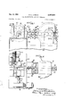
Figure l is a fragmentary end elevation of an illustrative feed mechanism embodying the present invention.
Fig. '2 is a plan view of the mechanism of Fig. 1.
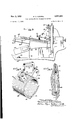
Fig. 3 is a fragmentary front elevation of the mechanism of Fig. l, the feed magazine and its mounting being shown in considerable detail.
Fig. 4 is an enlarged fragmentary perspective view showing the forward end of the magazine together with its adjustable gate member.
Fig. 5 is an enlarged fragmentary vertical sectional view taken through the grinding wheels and guide bars and in the plane of line 55 in Fig. 1.
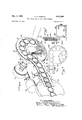
Fig. 6 is an enlarged fragmentary perspective view of the mechanism shown in Fig. 1-, the side guide members and one of the grinding wheels having been omitted for purposes of clearer illustration.
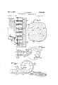
Fig. 7 is a fragmentary sectional view taken radially through the chuck and in the plane of the line l--! in Fig. 1.
Fig. 8 is an enlarged fragmentary vertical sectional view detailing the lower end of the magazine and a portion of the magnetic chuck, such view being taken in the plane of the line 8-8 in Fig. 2.
Fig. 9 is an enlarged fragmentary elevation of the face of the magnetic chuck member illustrating the layout of certain parts thereof.
Fig. 10 is a diagrammatic view of the face of the chuck and the guideways showing the manner in which the mechanism accommodates workpieces of different sizes.
Figs. 11 and 12 are diagrammatic views illustrating slightly modified feed mechanisms which also embody the present invention.
While the invention is susceptible of various modifications and alternative constructions, oertain preferred embodiments have been shown in the drawings and will be described below in considerable detail. It should be understood, however, that there is no intention to limit the invention to the specific forms disclosed, but on the contrary, the intention is to cover all modifications and alternative constructions falling within the spirit and scope of the invention as expressed in the appended claims.
Referring more specifically to the drawings, there is shown an illustrative feed mechanism 28 embodying the present invention and operatively associated with a grinding machine 2| having a pair of axially aligned, spaced apart abrasive wheels 22', 24. In the present instance, themechanism 29 is mounted on a base 25 which abuts rigidly against base 25 of the grinding machine 2!. The mechanism .20 comprises a trough-like magazine 28' which is capable of hold ing a stack of workpieces such as piston rings R, together with a transfer member in the form of a rotatable magnetic chuck 29. The latter is adapted to withdraw rings individually from the magazine 28 and to convey them in a continuous procession toward the diametrical grinding zone of the machine 2!. Rings are guided through such zone preferably by means of a pair of ver-- tically spaced guide bars 30 3| equidistant from the axis of the grinding wheels 22, 2t and extending between the grinding faces of the latter.
The magazine 28 (Figs. 2, 3 and 4) comprises an elongate trough of shallow V-shape and defined by side panels 32, 34. The structure is reinforced at intervals along its length by means of a series of longitudinally spaced transverse gusset plates welded or otherwise rigidly secured to the panels 32, 34. To facilitate loading, the panel 34 may have an outturned flange 36 integral with its upper edge. The magazine 28 is arranged so as to slope downwardly toward the chuck 29 and thereby create a tendency for the workpieces R to gravitate toward the face of the chuck. Although the degree of inclination is not particularly critical, it has been found convenient in the present instance to incline the magazine at an angle of approximately with the horizontal.
To obtain orderly movement of the workpieces R along the magazine 28, the latter is mounted upon a vibratory support (Fig. 3). Thus the lower or forward end portion of the magazine 28 is provided with a pair of spaced apart supporting plates 38 rigidly fixed to the panels 32, 34. The plates 38, in turn, are rigidly fixed to the armature 39 of a vibrator 491 The latter may be of any suitable design selected by those skilled in the art and in the present instance is of the electromagnetic type. The vibrator 40 has integral therewith a base 4| which is rigidly secured as at 42 to the base 25 of the feed mechanism. The upper end portion of the magazine 28 is preferably supported upon an upstanding leaf spring (not shown) which is capable of sustaining the weight of the magazine while permitting vibration longitudinally thereof.
In order to insure that only one of the workpieces R at a time will pass from the magazine 28 to the face of the magnetic chuck 29, an adjustable gate member 43 is disposed in transverse and overlying relation with the lower end portion of the magazine (Fig. 4). In the present instance, the member 43 is of inverted T-shape and its upstanding portion is formed with a mounting slot 44. Swivelly attached to the lateral extremities of the member 43 are a pair of L- shaped feet 45, each of the latter having fixed thereto a relatively short ski-like shoe 43. In the mechanism 28, the feet 45 are arranged radially of the workpieces R and with the lowermost or heel ends of their shoes 48 almost tangent to the outer peripheries of the underlying workpieces in the magazine. Due to the flux penetration of the first several workpieces in the magazine, they tend to move bodily parallel to the face of the chuck each time the lowermost workpiece is withdrawn. To prevent jamming of the workpieces against the toe of each of the shoes 46, the latter are slightly upturned. In addition, the toe end of each of the shoes 46 is preferably inclined at a slight angle to the longitudinal axis of the magazine (see Fig. 8) so as to effect a sort of funneling action toward the discharge end of the magazine.
The gate member 43 is supported by means of an upright bar 48 slidably housed within a bracket 49. The bar 48, and hence the member 43, can be positioned vertically by means of an adjusting knob 50 located at the top of the bracket 49, thus permitting the magazine to accommodate workpieces of various sizes and diameters. to permit adjustment of the member 43 in a direction generally longitudinal of the magazine, the bracket 49 is mounted for limited horizontal sliding movement which is effected by means of another adjusting knob 5|. It will be observed from Figs. 4 and 8 that when the gate member 43 is adjusted for feeding circular workpieces of a particular size the attached shoes 46 are spaced from the magnetic face of the chuck 29 by a distance slightly greater than the thickness of a single workpiece R but considerably less than the thickness of two workpieces together. Thus the foremost ring R in the magazine, as well as the next few rings adjacent thereto, are maintained in a vertical position and only one ring at a time is permitted to pass from the magazine to the chuck 29.
Means is provided for exerting a yieldable push in the vicinity of the trailing end of a procession of workpieces so as to force them through the grinding zone against the resistance of the grinding wheels over a wide range of cuts. This is accomplished by the continuous power feeding of the workpieces along the guide bars 38, 3| in a manner which takes full advantage of the permanent magnetism of the chuck 29. In further ance of such objective, an arcuate backing rail 52 (Figs. 1, 6 and 10) is fixedly mounted in overlying relation with a portion of the periphery of the chuck 29. The end of the backing rail 52 nearest the grinding wheels has fastened thereto an extension 54 which connects with upper guide bar 39. Spaced apart from and vertically below the extension 54 is a curved stripper bar 55. One end of the latter is supported by means of a standard 56 while its other end connects with the lower guide bar 3|. Between the extension 54 and the stripper bar 55, there are mounted a pair of closely spaced side guides 57 which straddle the path of the workpieces and confine the latter thereto. In the foregoing structure, the workpieces are drawn one by one from the magazine and positioned on the face of the chuck 29 by reason of the latters magnetic force. Without further repositioning, the chuck carries the workpieces bodily in an arcuate path defined primarily by the inner peripheral surface 58 of the backing rail 52, such surface when extended being tangent to the inner face of magazine panel 32.
Provision is made in the illustrative mechanism 20 for stripping the workpieces from the face of the chuck. In the present instance, this is accomplished by shifting the workpieces radially of the chuck 29. Such action is effected by means of the stripper bar 55 and the backing rail extension 54, both of which define a path curving from what might be considered a circumferential direction to a secantial direction with ref erence to the chuck.
By reason of the construction described above, it will be appreciated by those skilled in the art that the chuck 29 is adapted to exert a yieldable force upon the procession of workpieces approximately in proportion to the resistance of the grinding wheels. This, of course, is governed by the depth of cut. Where the cut is light and the resistance low, continuous feeding of the workpieces through the grinding zone can be effected with relatively little force, such, for example, as that which the chuck 29 would exert on the Workpieces RI and R2. On the other hand, where the cut is heavy and the resistance is substantially higher, a relatively large amount of force is required to feed the workpieces through the grinding zone. Under such circumstances, it might be necessary to have the force of the chuck exerted upon additional workpieces such as R3, R4 and R5 as well as RI and R2. Any gaps between these workpieces will be closed as a result of limited sliding of some of them along the face of the chuck due to the resistance or back pressure of the grinding wheels acting along the center line of the procession. The transmission of thrust along such line, notwithstanding its curvature, is of course made possible by the restraining action of the backing rail 52 as well as the extension 54 and stripper bar 55.
The foregoing arrangement is adapted to accommodate workpieces of different diameters readily and with a minimum of adjustment. Referring, for example, to Fig. 10, it will be noted 5 that the proportions of the magazine and the backing rail :52 remain the same regardless of the :diameter of the particular batch of workpieces received by the mechanism 20. The spacingiof backing rail extension 54, stripper bar 55 and side guides 51, as well as that of guide bars 30,.3-Lzmust, however, be altered to accommodate different sized workpieces. For this purpose, a pair of adjusting screws, each having a knurled knob 60, are :mountedat theoppos-ite extremities i of the guide bars 30,-3l, the construction at only one end of the bars being shown in the drawings. Eachscrew is threaded along its length with the leads of the thread reversed in the mid portion of thescrew. Opposite ends of eachscrew threadedly engageoooperating :screw blocks 6! fixed to the :ads'acent ends of the respective guide bars 30, 31.. 'Thus, the guide bars can be adjusted simul-taneously toward and from each -:other by reverse :rotation of the threads by the knobs '69. Pivotally secured at one end to the block tl of the upper guide bar 30 .and at the other end to one extremity of thebacking rail 52 is the extension 54. The stripper bar 55, on the other hand, islpi-votally fixed .to the blocktl of the lower guide bar. The other end of the bar 55 is adjustably secured to the standard 55 and is movable in a vertical direction. Adju-stmentof the side guides 51 may readily be eifected by the use of adjustingzknobs-2 (-Fig. 2).
Turning now to the magnetic chuck 29, it will be perceived that this member comprises a disc 63 fixed to :fla-ngeM of drive shaft 635. The latter is journaled mai-n supporting bearing 66 anchored on the frame of the mechanism 20. The disc 63 is preferably formed of material having a high permeabilitysuch as soft steel or the like and has a large annular recess 5 in its face. Disposed upon floor 6B of the recess 61 so as to produce a number of :spaced apart, alternate poles, are a plurality of relativelysmall permanent magnets 69. In the present instance, the magnets 69 are of round :bar stock and :are formed from an alloy having a high magnetic retentivitysuch as that known commercially as Alnico. Magnctic elements having different forms and compositions may also :be used with effectiveness.
Provision is made in the chuck 2:9 for obtaining a magnetic field of the proper intensity to avoid creating excessive friction between the adjacent workpieces which would unduly resist lateral sliding movement of the foremost workpiece in the magazine relative to the next succeeding piece and thereby hamper the successive transfer of workpieces from the magazine to the chuck. Yet the field ismade suiiiciently strong to permit the power feeding of workpieces to the grinding zone throughout a large range of wheel resistances. This is accomplished in the present instance y interspersing among the magnets 69 a plurality of plugs 10 .(Figs. 8 and 9). The latter may be of soft iron or other high permeability material but are not permanently magnetized, thereby reducing the intensity of the field produced on the face of the chuck 29. With such arrangement, each plug is surrounded by a plurality of closely spaced poles of each polarity, thereby accommodating the chuck 29 to. ring and disc-shaped workpieces of widely varying diameter. In certain cases where hard wear on the surface of the chuck must be combatted, the face end portions \of the plugs 10 might be surrounded by washers made of particularly hard material such as tungsten carbide. In still other applications, it might be possible to obtain a field 6 of the desired intensity by dispensing with the plugs 70 altogether.
To produce regular and uni-form spacingof the magnets and plugs 59, I0 during assembly on the disc 63, a number of these parts may be fitted with washers ll of brass or other non-magnetic material. .After such members have been positioned in properly spaced relation upon the recess floor 58, a matrix of low melting point base metal i2 is cast around them and finished off even with the face of the disc 63. The matrix l2, in turn, is mechanically anchored in the annular recess -51 as by means of anchor grooves 13 in the opposed, generally cylindrical :surfaces on the body portions of the disc '63 defining the-inner and outer circumferential-edges of the recess, see Fig. '7.
The mechanism '23 includes .means for selectively varying the rate at which pieces are fed to the grinding wheels 22, 2:1. For this purpose, the magnetic chuck 29 is equipped with a variable speed drive comprising a motor 2'4 and a speed reducer it which happens to be of the worm and gear type. Power is transmitted to the speed reducer by motor shaft 16 and is transmitted from the speed reducer by means of shaft J3 which is connected to the chuck drive shaft through a coupling 19.
Referring now to Fig. 11, there is shown in diagrammatic form a modified feed mechanism similar to the mechanism 20 but having the l tgazine located between the rotational axis of t e chuck and the grinding zone rather than on the opposite side of the chuck axis as in the mechanism In the modified construction, the axis 1e chuck as does not lie in the same horical plane as the axis of the grinding wheels but is oifset vertically therefrom. This arrangement permits workpieces to accumulate around substantially the entire face of the chuck 29, the workpieces leaving the chuck tangentially after almost a complete revolution of bodily movement therewith. I'he mechanism 20A may have .a modified backing rail at extending circumferentially and clockwise from a point slightly above the magazine and terminating in an integral extension horizontally aligned with the lower guide bar 35. Such construction is advantageous for heavy cuts where it is necessary to utilize to the .iaximum possible extent the magnetism of the chuck 2:; so as to obtain a sufficient pushing force on the workpiece.
lhe modified feed mechanism 20B shown diagrammatically in l2 closely resembles the mechanism 20A. It differs, however, in that the axis of the chuck is located below the grinding zone and the workpieces are fed-downwardly from the magazine instead of upwardly. In other words, the chuck of the mechanism 20B rotates counterclockwise as viewed in Fig. 12. The backing rail and stripper bar of the mechanism 203 are substantially identical with those of the mechanism 29A.
At this point, it will be apparent that the feed mechanisms described herein possess a number of advantages in addition to those already discussed. First of all, since the mechanisms produce a positive feed, they are independent of gravity and susceptible of operationin any plane. Notwithstanding their positive action, the risk of breakage of workpieces by the mechanisms 2B,-
26A and 20B is negligible because of the yieldable nature-of the force applied. The close spacing of magnets in the chuck 23 reduces fiux penetration but at the same time preserves field intensity.
Upon release from the magazine 28, the workpieces are immediately oriented in the plane of the grinding zone and require no further orientation. They are also released from the magazine in the proper position relative to the magnetic chuck 29 and subsequent repositioning on the face of the chuck is entirely unnecessary. The guiding arrangement is such that the rings are always maintained in exactly the correct position for grinding. In addition, the absence of feed rolls and complex handling equipment, together with the foregoing features, renders the mechanism susceptible of extremely high, as well as low, rates of feed. For example, one feed mechanism embodying the present invention has proven itself capable of feeding piston rings into a grinding machine at rates in the neighborhood of 1,000 per minute. Since the chuck occupies a position relatively remote from the grinding zone, its face will only be subject to normal wear produced by the sliding of the workpieces thereon and will not be subjected to additional and abnormal wear due to the accumulation and grating of abrasive particles thereon.
I claim as my invention:
1. A feed mechanism for a grinding machine having grinding wheels defining a grinding zone and a pair of spaced apart guide bars extending through the grinding zone in straddling relation with the central portion thereof, said feed mechanism comprising, in combination, a rotatable magnetic chuck of disc shape forming a fiat face thereon, an elongated trough-shaped magazine adapted to hold a stack of workpieces and to present the same individually to the face of said chuck, said trough being mounted with the elongated axis thereof disposed at a substantial angle to the plane of said chuck face, said trough having a gate end thereon disposed in op posing relation to said chuck face at a position radially within the peripheral edge thereof, a fixed backing rail overlying a portion of the peripheral surface of said chuck and adapted to constrain the workpieces on the latters face to move bodily therewith in a concentric path, the inner peripheral surface of said backing rail being substantially tangent to one face of said trough-shaped magazine, a backing rail extension located between said backing rail and one of said guide bars, opposite ends of said extension being substantially alined with adjacent ends of said backing rail and said one guide bar, said backing rail extension having a reverse curve therein leading away from the axis of said chuck, a stripper bar disposed in spaced relation from said extension and having a similar curvature therein to effect alignment of one end of said stripper bar with the other of said guide bars, magnetic means disposed contiguous to said chuck face and emitting magnetic flux outwardly thereof in a substantially continuous arcuate band reaching across said trough gate and extending circumferentially to said stripper member, and driving means connected in driving relation to said magnetic chuck for causing rotation thereof to effect a yieldable push on said workpieces so as to feed them in a continuous procession through the grinding zone via the path defined by said backing rail, said extension, said stripper bar and said guide bars.
2. A mechanism for power feeding piston rings and the like with a yieldable force to a grinding machine having a pair of spaced apart and adjustable guide bars extending through the grind- 8 ing zone, said mechanism comprising the combination of a downwardly inclined magazine adapted to hold a stack of workpieces, supporting means disposed in supporting relation to said magazine and including a vibrator, a magnetic chuck disposed contiguous to the lower end of said magazine and having a plurality of permanent magnets defining in its face areas of alternate polarity, said chuck being adapted to receive said workpieces one at a time from said lower end of said magazine, a variable speed drive operatively connected with said chuck for causing rotation thereof, an arcuate backing rail over-- lying a portion of the periphery of said chuck and defining a path for workpieces concentric with the axis of said chuck, a backing rail extension pivotally secured at one end to said backing rail and adapted at the other end for pivotal attachment to one of said guide bars, said extension curving reversely away from said backing rail, a stripper bar associated with said chuck and adjustably secured at one end to a fixed support and susceptible of pivotal attachment at its opposite end to the other one of said guide bars, said stripper bar being spaced from said backing rail extension but having a similar curvature therein for interception of workpieces moving bodily with said chuck, and a pair of adjustable side guides mounted on opposite sides of the flat space bounded on one edge by said rail extension and said one guide bar and on the other edge by said stripper bar and said other guide bar, said side guides extending generally between said magnetic chuck and the grinding zone of the ma-' chine.
3. In a feed mechanism for a grinding machine, the combination of a rotatable disc of material having a relatively high permeability, said disc also defining an annular recess in the face thereof, said recess being bounded at the inner and outer circumferential edges thereof by annular portions of the body of said disc, the radially opposed surfaces of said annular disc body portions defining opposed anchor grooves therein, a plurality of bar-shaped permanent magnetic elements disposed in spaced relation within said recess and with their outer ends arranged so as to produce a plurality of areas of alternate polarity in the plane of the face of said disc, the inner ends of said elements being disposed in firm abut-' ting engagement with the bottom of said recess to have intimate magnetic contact with said disc,
and a matrix of base metal adapted to retain said permanent magnetic elements within the recess, said base metal being disposed within said anchor grooves and in the interstices between said magnetic elements.
4. In a feed mechanism for a grinding machine, a permanent magnetic chuck comprising, in combination, a rotatable disc of material having a relatively high permeability, said disc also having an annular recess in the face thereof, a plurality of bar-shaped permanent magnetic elements disposed in spaced relation within said recess and with their ends arranged so as to produce a plurality of areas of alternate polarity in the plane of the face of said disc, a plurality of bar-shaped but unmagnetized elements of relatively high permeability material interspersed with said magnetic elements, a matrix of base metal disposed within the interstices between said magnetic elements and said unmagnetized ele-' magnetic elements and said unmagnetized elements-within the recess of said disc.
5. In a feed mechanism for a grinding machine, a permanent magnetic chuck comprising the combination of a disc of material having a relatively high permeability, said disc also hav-- ing a recess in the face thereof, driving means operatively connected with said disc for causing rotation thereof, a plurality of permanent magnetic elements disposed in spaced relation within said recess and with their outer ends arranged so as to produce a plurailty of areas of alternate polarity in the plane of the face of said disc, the inner ends of said elements being disposed in intimate magnetic contact with said disc, a plurality of unmagnetized plugs of hardened, wear resistant material interspersed with said magnetic elements and adapted to control the intensity of the magnetic field set up by the latter, a matrix of base metal disposed within the interstices between said magnetic elements and said unmagnetized plugs, and anchoring means on said disc positively engaging said matrix to securely retain said magnetic elements and said unmagnetized plugs within the recess of said disc.
6. In a feed mechanism for a grinding machine, the combination comprising a rotatable chuck in the form of a disc having a fiat end face thereon, a trough-like magazine adapted to hold a, stack of workpieces, means supporting said magazine in downwardly inclined position with its lower end terminating in closely spaced opposing relation with the face of said chuck at a position radially within the peripheral edge of the face, said supporting means including a vibrator for effecting vibration of said magazinc and its contents whereby the latter tend to gravitate toward the face of said chuck, an adjustable gate member mounted adjacent said lower end of said magazine for holding the stack of workpieces erect, said gate member having a shoe running generally longitudinally of said magazine but spaced from the face of said chuck by a. distance sufficient to permit only one workpiece at a time to be withdrawn from said chuck, and an arcuate series of magnets on said chuck contiguous to said chuck face and emitting magnetic flux outwardly thereof in a substantially continuous band reaching across said lower end of said magazine trough and extending circumferentially around said chuck, said magnets serving as an incident to rotation of said chuck to withdraw successive workpieces individually from said magazine to accumulate them in an annular, side by side array on said chuck face.
7.v The combination of a grinding machine having oppositely disposed abrasive wheels and guide bars disposed therebetween and adapted to channel workpieces through a path alongside the wheels for simultaneous grinding of both sides of the workpieces, with a feed mechanism comprising guide means associated with said guide bars, a magazine mounted in assembled relation with said machine and adapted to hold a supply of workpieces, a rotatable chuck having a smooth face disposed adjacent the outlet of said magazine, magnets disposed in said chuck for magnetizing said face, said magnets producing magnetic flux about said chuck face for withdrawing workpieces individually from said magazine and for causing them to adhere to said face in side-by-side relation upon rotation of said chuck, means located in overlying relation to said magnetic chuck face and adapted to guide the workpieces from said face into the path defined by said guide bars, said magnetic face upon rotation of said chuck serving to yieldably feed acontinuous procession of workpieces along said guide bars between said abrasive wheels.
8. A high speed grinder comprising, in combination, a grinding machine having a pair of opposed rotary abrasive wheels defining a grinding zone for finishing opposite ends of workpieces, a pair of generally parallel guides mounted in said zone for channeling a succession of workpieces across said wheels, a workpiece feeding chuck rotatably mounted adjacent the inlet end of said guides, driving means operatively connected to said chuck, said chuck defining a smooth, fiat annular face perpendicular to the rotary axis thereof, magnet means disposed contiguous to said chuck face and emitting magnetic flux outwardly thereof, an elongated magazine shaped to contain a stack of workpieces and having a gate end disposed in opposing relation to said chuck face at a position radially within the peripheral edge of the face, said chuck upon rotation thereof being adapted to withdraw workpieces individually from said magazine to form an annular array on said chuck face, gate members on the gate end of said magazine disposed in predetermined spaced relation to said chuck face to permit only a single layer of workpieces to be depositedon said chuck face, an arcuate backing rail overlying a segment of the periphery of said chuck face extending circumferentially generally from said magazine gate, intermediate guide means interconnecting one of said guides with the end of said rail circumferentially remote from said magazine, and a workpiece stripper barinter-- connected with said other guide and extending across said chuck face in generally parallel relation thereto to a position radially within the periphery thereof.
9. A high speed grinder comprising, in combination, a grinding machine having two opposed rotary abrasive wheels defining a grinding zone for finishing opposite surfaces of workpieces upon,
a single pass therethrough, a pair of generally parallel guides extending through said zone for channeling a succession of workpieces across said wheels, a workpiece feeding chuck rotatably mounted adjacent the inlet end of said guides, driving means operatively' connected to said chuck, said chuck defining a smooth, flat annular face perpendicular to the rotary axis thereof, an elongated magazine, shaped to contain a stack of workpieces and having a gate end disposed in opposing relation to said chuck face, magnet means disposed contiguous to said chuck face and emitting magnetic flux outwardly thereof in a substantially continuous band reaching across said magazine gate and extending circumferentially along said face, said magnets upon rotation of said chuck being adapted to withdraw workpieces individually from said magazine to form an annular side by side array onsaid chuckface, a stationary, arcuate backing rail overlying a segment of the periphery of said chuck face extending circumferentially generally from, said magazine gate, intermediate guide means interconnecting one of said guides with the end of said rail circumferentially remote from said magazine, and a stationary workpiece stripper bar interconnected with said other guide and extending obliquely across said chuck face in generally parallel relation thereto to a position radially within the periphery thereof, said stripper bar being disposed in spaced complementary relation to said intermediate guide means.
10. For use with a grinding machine having a pair of opposed grinding wheels defining a grinding zone and a pair of generally parallel spaced guides extending through the zone, an automatic high speed feeder for yieldably forcing a procession of workpieces along the spacing between said guides, said feeder comprising a rotary chuck defining a flat annular face perpendicular to the rotary axis of said chuck, driving means operatively connected to said chuck, an elongated magazine section shaped to contain a stack of workpieces and having a gate end disposed in opposing relation to said chuck face at a position radially within the peripheral edge of the face, the longitudinal axis of said magazine section being disposed at a substantial angle relative to the plane of said chuck face, gate members on said gate end of said magazine disposed in predetermined spaced relation to said chuck face to permit only a single layer of workpieces to be deposited on said chuck face, an elongated intermediate guide member adapted to be connected to the inlet end of one of the grinder zone guides of the grinding machine and having a portion thereof disposed in generally tangential relation to a peripheral portion of said chuck face circumferentially removed from said magazine gate end, an elongated stripper member adapted to be connected to the inlet end of the other of said grinding zone guides, said stripper member extending across a radially inward portion of said chuck face in spaced complementary relation to said intermediate guide member, and magnetic means underlying an annular portion of said chuck face opposing said magazine gate end and extending circumferentially therefrom to said strip-per member.
11. For use with a grinding machine having a pair of opposed grinding wheels defining a grinding zone and a pair of generally parallel spaced guides extending through the zone, an automatic high speed feeder for yieldably forcing a procession of workpieces along the spacing between said guides, said feeder comprising a rotary chuck defining a flat annular face perpendicular to the rotary axis of said chuck, driving means operatively connected to said chuck, an elongated magazine section shaped to contain a stack of workpieces and having a gate end disposed in opposing relation to said chuck face at a position radially within the peripheral edge of the face, the longitudinal axis of said magazine section being disposed at a substantial angle relative to the plane of said chuck face, gate members on said gate end of said magazine disposed in adjustable predetermined spaced relation to said chuck face to permit only a single layer of workpieces to be deposited on said chuck face, a stationary backing rail overlying a segment of the periphery of said chuck face extending circumferentially generally from said magazine gate, an extension on said backing rail curved reversely therefrom and adapted to be connected to the inlet end of one of the grinder zone guides of the grinding machine, a stationary, elongated stripper member adapted to be connected to the inlet end of the other of said grinding zone guides, said stripper member curved reversely to said backing rail and extending diagonally across said chuck face in spaced complementary relation to said rail extension and disposed radially inward of said extension relative to said chuck, and magnetic means underlying an annular portion of said chuck face opposing said magazine gate end and extending circumferentially therefrom to said stripper member.
12. An automatic high speed feeder for yieldably forcing a procession of workpieces along a path defined by a pair of spaced complementary guides, said feeder comprising, in combination, a rotary chuck having a smooth flat annular face perpendicular to the chuck axis, an elongated magazine shaped to contain a stack of workpieces and disposed at a steeply inclined angle relative to said chuck face, said magazine having a gate end spaced a predetermined distance from said chuck face and disposed in opposing relation thereto at a position thereon radially within the peripheral edge of the face, an arcuate backing rail overlying a circumferential segment of the periphery of said chuck face extending generally from said magazine gate, an elongated extension connected to said backing rail and adapted to be connected to one of the complementary guides, a workpiece stripper member adapted to be connected to the other of the complementary guides and extending into overlying relation to said chuck face in spaced complementary relation to said rail extension on the radially inward side thereof relative to said chuck, magnet means disposed contiguous to said chuck face and emitting magnetic flux outwardly thereof in an arcuate band reaching across said magazine gate end and extending ciroumferentially to said stripper member, and said magnetic means being arranged so that circumferential discontinuities in said flux band are limited to breaks substantially shorter than the spacing between said stripper member and said rail extension whereby said magnetic means is enabled as an incident to rotation of said chuck to withdraw workpieces individually from said magazine and accumulate them in an arcuate, substantially side by side array on said chuck face reaching to said stripper member.
13. For use with a grinding machine having opposed grinding wheels defining a grinding zone and guide means extending through the zone, an automatic high speed feeder for yieldably forcmg a procession of workpieces along said guide means and comprising, in combination, a rotary magnetic chuck defining a flat annular face havmg a smooth surface, driving means connected tosaid chuck, an elongated magazine for contaming a stack of workpieces and having a gate end thereon disposed in contiguous spaced relation to said chuck face at a location thereon radially inward of the periphery thereof, an arcuate arrangement of magnetic means disposed contiguous to said chuck face and emitting beyond said face a substantially continuous band of magnetic flux reaching across said magazine gate end and extending circumferentially therefrom along aid face, a stationary elongated stripper member disposed in contiguous overlymg relation to said face at a position thereon circumferentially removed from said magazine gate end, said stripper member being curved reversely to the periphery of said annular face and extending obliquely across said face beyond said periphery thereof from a radially inward portion of said face, stationary arcuate backing rail means disposed in overlying relation to a. circumferential segment of the periphery of said chuck face between said magazine gate and said stripper member, extension means on said rail curving reversely away from said chuck periphery in spaced complementary relation to said stripper member, and the outer ends of said extension means and said stripper member being adapted for connection to the grinding machine guide means.
14. A high speed continuous feed grinder comprising, in combination, a pair of opposed rotary abrasive wheels defining a grinding zone for finishing opposite surfaces of workpieces upon a single pass therethrough, workpiece guide means comprising a pair of spaced parallel guides extending through said zone, a rotary disc-like chuck defining a fiat annular face having a smooth surface perpendicular to said chuck axis, driving means connected to said chuck, an elongated magazine for containing a stack of workpieces and having a gate end thereon disposed in contiguous spaced relation to said chuck face at a location thereon radially inward of the periphery thereof, an annular group of permanent magnets fixed in said chuck and emitting beyond said chuck face a substantially continuous annular band of magnetic flux reaching across said magazine end gate and extending circumferentially around said face, a stationary elongated stripper member disposed in contiguous overlying relation to said face at a position thereon circumferentially removed from said magazine gate end, said stripper member extending obliquely across said face beyond said periphery thereof from a radially inward portion of said face, and means connecting the outer end of said stripper member to said workpiece guide means.
15. An automatic high speed feeder for yieldably forcing a procession of workpieces along a path defined by a pair of vertically spaced complementary guides, said feeder comprising, in combination, a disc-like chuck mounted for rotation about a horizontal axis and having a smooth fiat annular face perpendicular to the chuck axis, an elongated magazine shaped to contain a stack of workpieces and having a gate outlet on one longitudinal end thereof spaced a predetermined distance from the vertical face of said chuck and disposed in opposing relation thereto at a position thereon radially within the peripheral edge of the face, said magazine being inclined upwardly from said gate end, an arcuate backing rail overlying a circumferential segment of the periphery of said chuck face extending generally from said magazine gate, an elongated extension connected to said backing rail and adapted to be connected to one of the complementary guides, a workpiece stripper member adapted to be connected to the other of the complementary guides and extending into overlying oblique relation to said chuck face in spaced complementary relation to said rail extension on the radially inward side thereof relative to said chuck, and a plurality of permanent magnets imbedded in said chuck in an annular group and emitting magnetic flux outwardly of said chuck face in an arcuate band reaching across said magazine gate end and extending circumferentially around said face under said stripper member, said magnets serving as an incident to rotation of said chuck to withdraw workpieces individually from said magazine and accumulate them in an arcuate, substantially side by side array on said chuck face reaching to said stripper member.
HAROLD O. CADMAN.
References Cited in the file of this patent UNITED STATES PATENTS Number Name Date 687,931 Barr Dec. 3, 1901 751,791 Haskins Feb. 9, 1904 962,030 Kirkgaard June 21, 1910 1,358,725 Gaynor h Nov. 16, 1920 1,414,522 Morgan May 2, 1922 1,451,268 Morgan Apr. 10, 1923 1,519,417 Payne Dec. 16, 1924 1,548,563 Spencer Aug. 4, 1925 1,628,618 Spencer May 10, 1927 1,682,925 Miller Sept. 4, 1928 1,983,471 Kramer Dec. 4, 1934 2,179,625 Groden Nov. 14, 1939 2,347,023 Beechlyn Apr. 18, 1944 FOREIGN PATENTS Number Country Date 279,089 Germany Oct. 9, 1914
Priority Applications (1)
| Application Number | Priority Date | Filing Date | Title |
|---|---|---|---|
| US126377A US2657504A (en) | 1949-11-09 | 1949-11-09 | Feed mechanism for grinding machines |
Applications Claiming Priority (1)
| Application Number | Priority Date | Filing Date | Title |
|---|---|---|---|
| US126377A US2657504A (en) | 1949-11-09 | 1949-11-09 | Feed mechanism for grinding machines |
Publications (1)
| Publication Number | Publication Date |
|---|---|
| US2657504A true US2657504A (en) | 1953-11-03 |
Family
ID=22424508
Family Applications (1)
| Application Number | Title | Priority Date | Filing Date |
|---|---|---|---|
| US126377A Expired - Lifetime US2657504A (en) | 1949-11-09 | 1949-11-09 | Feed mechanism for grinding machines |
Country Status (1)
| Country | Link |
|---|---|
| US (1) | US2657504A (en) |
Cited By (11)
| Publication number | Priority date | Publication date | Assignee | Title |
|---|---|---|---|---|
| US2764850A (en) * | 1955-08-17 | 1956-10-02 | Besly Welles Corp | Magnetic feed for grinding machine |
| US2784534A (en) * | 1953-07-20 | 1957-03-12 | Heald Machine Co | Internal grinding machines |
| US2835085A (en) * | 1955-11-21 | 1958-05-20 | Hanchett Magna Lock Corp | Magnetic dial feeder |
| US2882650A (en) * | 1954-11-18 | 1959-04-21 | Gardner Machine Co | Size and alignment control means |
| US2884747A (en) * | 1955-09-30 | 1959-05-05 | Landis Tool Co | Magnetic holder |
| US3427643A (en) * | 1966-03-14 | 1969-02-11 | Zech Murray Corp | Metal finishing apparatus |
| JPS4817793U (en) * | 1971-07-08 | 1973-02-28 | ||
| US3803769A (en) * | 1973-04-03 | 1974-04-16 | Bendix Corp | Work feeder for a double disc grinder |
| US5393395A (en) * | 1990-03-16 | 1995-02-28 | Daido Metal Company, Ltd. | Method of surface-treating a half sliding bearing and apparatus for same |
| CN104648990A (en) * | 2013-11-18 | 2015-05-27 | 慈溪市大道机械厂 | Bearing inner/outer ring polishing machine and bearing inner/outer ring conveying mechanism |
| WO2017204759A1 (en) | 2016-05-26 | 2017-11-30 | Ortadogu Rulman Sanayi Ve Ticaret Anonim Sirketi | Side face grinding system for bearing rings |
Citations (14)
| Publication number | Priority date | Publication date | Assignee | Title |
|---|---|---|---|---|
| DE279089C (en) * | ||||
| US687931A (en) * | 1900-08-06 | 1901-12-03 | Linotype Co | Magnetic holding-table for metal-working machines. |
| US751791A (en) * | 1904-02-09 | Machine for grinding metal surfaces | ||
| US962030A (en) * | 1908-12-16 | 1910-06-21 | Imp Stopper Company | Feeding mechanism for bottle-capping machines. |
| US1358725A (en) * | 1918-03-28 | 1920-11-16 | Arrow Bottlers Machinery Compa | Magnetic crown-cap selector |
| US1414522A (en) * | 1918-05-15 | 1922-05-02 | Greenfield Tap & Die Corp | Magnetic chuck and method of making the same |
| US1451268A (en) * | 1919-03-05 | 1923-04-10 | Greenfield Tap & Die Corp | Magnetic chuck |
| US1519417A (en) * | 1924-03-07 | 1924-12-16 | Clarence Q Payne | Electromagnetic clutch |
| US1548563A (en) * | 1922-10-06 | 1925-08-04 | Blanchard Machine Company | Means for handling articles |
| US1628618A (en) * | 1922-10-06 | 1927-05-10 | Blanchard Machine Company | Means for handling articles |
| US1682925A (en) * | 1928-09-04 | Assigitob to charles h | ||
| US1983471A (en) * | 1931-07-22 | 1934-12-04 | Crown Cork & Seal Co | Conveyer mechanism |
| US2179625A (en) * | 1938-09-01 | 1939-11-14 | John J Groden | Work holder |
| US2347023A (en) * | 1941-02-07 | 1944-04-18 | O S Walker Co Inc | Permanent magnet chuck |
-
1949
- 1949-11-09 US US126377A patent/US2657504A/en not_active Expired - Lifetime
Patent Citations (14)
| Publication number | Priority date | Publication date | Assignee | Title |
|---|---|---|---|---|
| US1682925A (en) * | 1928-09-04 | Assigitob to charles h | ||
| US751791A (en) * | 1904-02-09 | Machine for grinding metal surfaces | ||
| DE279089C (en) * | ||||
| US687931A (en) * | 1900-08-06 | 1901-12-03 | Linotype Co | Magnetic holding-table for metal-working machines. |
| US962030A (en) * | 1908-12-16 | 1910-06-21 | Imp Stopper Company | Feeding mechanism for bottle-capping machines. |
| US1358725A (en) * | 1918-03-28 | 1920-11-16 | Arrow Bottlers Machinery Compa | Magnetic crown-cap selector |
| US1414522A (en) * | 1918-05-15 | 1922-05-02 | Greenfield Tap & Die Corp | Magnetic chuck and method of making the same |
| US1451268A (en) * | 1919-03-05 | 1923-04-10 | Greenfield Tap & Die Corp | Magnetic chuck |
| US1548563A (en) * | 1922-10-06 | 1925-08-04 | Blanchard Machine Company | Means for handling articles |
| US1628618A (en) * | 1922-10-06 | 1927-05-10 | Blanchard Machine Company | Means for handling articles |
| US1519417A (en) * | 1924-03-07 | 1924-12-16 | Clarence Q Payne | Electromagnetic clutch |
| US1983471A (en) * | 1931-07-22 | 1934-12-04 | Crown Cork & Seal Co | Conveyer mechanism |
| US2179625A (en) * | 1938-09-01 | 1939-11-14 | John J Groden | Work holder |
| US2347023A (en) * | 1941-02-07 | 1944-04-18 | O S Walker Co Inc | Permanent magnet chuck |
Cited By (11)
| Publication number | Priority date | Publication date | Assignee | Title |
|---|---|---|---|---|
| US2784534A (en) * | 1953-07-20 | 1957-03-12 | Heald Machine Co | Internal grinding machines |
| US2882650A (en) * | 1954-11-18 | 1959-04-21 | Gardner Machine Co | Size and alignment control means |
| US2764850A (en) * | 1955-08-17 | 1956-10-02 | Besly Welles Corp | Magnetic feed for grinding machine |
| US2884747A (en) * | 1955-09-30 | 1959-05-05 | Landis Tool Co | Magnetic holder |
| US2835085A (en) * | 1955-11-21 | 1958-05-20 | Hanchett Magna Lock Corp | Magnetic dial feeder |
| US3427643A (en) * | 1966-03-14 | 1969-02-11 | Zech Murray Corp | Metal finishing apparatus |
| JPS4817793U (en) * | 1971-07-08 | 1973-02-28 | ||
| US3803769A (en) * | 1973-04-03 | 1974-04-16 | Bendix Corp | Work feeder for a double disc grinder |
| US5393395A (en) * | 1990-03-16 | 1995-02-28 | Daido Metal Company, Ltd. | Method of surface-treating a half sliding bearing and apparatus for same |
| CN104648990A (en) * | 2013-11-18 | 2015-05-27 | 慈溪市大道机械厂 | Bearing inner/outer ring polishing machine and bearing inner/outer ring conveying mechanism |
| WO2017204759A1 (en) | 2016-05-26 | 2017-11-30 | Ortadogu Rulman Sanayi Ve Ticaret Anonim Sirketi | Side face grinding system for bearing rings |
Similar Documents
| Publication | Publication Date | Title |
|---|---|---|
| US2657504A (en) | Feed mechanism for grinding machines | |
| US2170672A (en) | Apparatus for abrading coatings from rods | |
| US2535719A (en) | Magnetic pulley | |
| US2043972A (en) | Centerless grinding machinery | |
| US3101577A (en) | Methods of grinding or polishing elongated rotational bodies | |
| US4094412A (en) | Rolling method of sorting particulate articles | |
| US1384756A (en) | Carbon-cutting machine | |
| US1548563A (en) | Means for handling articles | |
| US1628618A (en) | Means for handling articles | |
| CA1057035A (en) | Assembling nails and washers | |
| US3029918A (en) | Device for feeding closure caps | |
| US2819816A (en) | Device for feeding work pieces | |
| US2981038A (en) | Method of grinding helical forms | |
| US1923931A (en) | Grinding machine | |
| US2845165A (en) | Can aligning means | |
| US5388374A (en) | Apparatus and method for grinding points | |
| US2264302A (en) | Precision grinding machine | |
| US1952777A (en) | Magnetic handling | |
| US4008805A (en) | Apparatus and method for sorting objects according to length | |
| US2883197A (en) | Magnetic driver for annular work | |
| US3160996A (en) | Work feeding device | |
| US1647130A (en) | Art of grinding | |
| CN209531993U (en) | A kind of automatic flat die thread-rolling machine charging block mechanism | |
| US1676620A (en) | Grinding apparatus | |
| US3106011A (en) | Milling cutter |