US2631663A - Article holding device - Google Patents
Article holding device Download PDFInfo
- Publication number
- US2631663A US2631663A US238933A US23893351A US2631663A US 2631663 A US2631663 A US 2631663A US 238933 A US238933 A US 238933A US 23893351 A US23893351 A US 23893351A US 2631663 A US2631663 A US 2631663A
- Authority
- US
- United States
- Prior art keywords
- guide
- bar
- spring
- casing
- tie
- Prior art date
- Legal status (The legal status is an assumption and is not a legal conclusion. Google has not performed a legal analysis and makes no representation as to the accuracy of the status listed.)
- Expired - Lifetime
Links
Images
Classifications
-
- A—HUMAN NECESSITIES
- A47—FURNITURE; DOMESTIC ARTICLES OR APPLIANCES; COFFEE MILLS; SPICE MILLS; SUCTION CLEANERS IN GENERAL
- A47H—FURNISHINGS FOR WINDOWS OR DOORS
- A47H19/00—Rosettes for holding curtains; Festoon holders
Definitions
- This invention relates to improvements in article holding devices, and particularly to improvements in curtain tie-back holders adapted to cooperate with the curtain tie-backs commonly used in connection with window and door curtains.
- the devices object of this invention are of simple and inexpensive construction, and can be quickly and simply applied to a window or door casing.
- this invention allows to move the tie-back and change its position relative to the casing and the curtain without changing the position of the holder on the window or door casing, and without requiring the substitution of one holder for another. In this manner, the shape of the draping of a curtain can be modified at will, with a single device object of the invention.
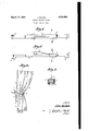
- Fig. 1 is a side view, partially broken away and rotated 90 counterclockwise, of an embodiment of this invention
- Fig. 2 is a front elevation corresponding to and rotated as Fig. 1;
- Fig. 3 is a cross-sectional view along line 3-3 of Figs. 1 and 2;
- Fig; 4 is a partial front elevation of a window or door side casing showing a curtain and its tiebackused in connection with an embodiment of the holders of the invention.
- the curtain tie-back holder comprises a guide-bar I of substantial length terminating at each end by an abutment 2 projecting from the same side of the guide-bar.
- the guide-bar is attached vertically to the side of the casing 3 of a window or door by means of screws or nails engaging holes 4 in the ends thereof; said holes may be threaded or smooth according to the means used to attach the guide-bar to the casing.
- the arrangement is such that, when the guide-bar is secured to the casing, there is a clearance between the easing and the portion of the guide-bar intermediate abutments 2 (see Fig. 4).
- a movable member 5 is slidingly mounted on and around said guide bar I; its thickness is less than the aforesaid clearance, in order that it may be moved along the guide-bar between said abutments 2.
- spring 6 moves along guide-bar I with movable member 5 and that its end I can be moved along the guide-bar over a length equal to the distance between abutments 2 less the total length of member 5 and spring 6. For example, if the length of guide-bar I between abutments 2 is 24 inches, and the total length of member 5 and spring 6 4 inches, then end I of the spring can travel over a length of 20 inches on the guidebar.
- the pressure of end I of spring 6 on the guide bar should be such as to hold the spring and the member 5 in position, once the latter has been selected.
- a change of position of member 5 and spring 6 along bar I is effected by springing manually or otherwise spring end I away from the guide-bar I and then moving the member 5 or attached spring 6. When the desired position has been reached, the spring 6 is then released.
- a tie-back 3 for a curtain 9 is inserted at its holding end I0 between end I of spring 6 and the outer face of guide-bar I, after the proper position of spring 6 has been determined along the bar with respect to the casing and the draping effect to be achieved.
- the pressure of spring 6 on the guide-bar holds the tie-back in position.
- the parts may be made of any suitable material, such as metal or plastic.
- a holder for drapery tie-backs which comprises: an elongated guide member, having at each end a projection attachable to a casing; a movable member slidingly engaging said guide member between said projections; a spring having one end attached to said movable member and the other end yieldingly contacting said guide member; said spring cooperating with said guide member to hold said movable member in a predetermined position :along said @guide :member, solely by the pressure exerted by-said other-end against said guide member.
- a holder for curtain tie-backs mountable on a casing, which comprises: an elongated guide member, having at each end a projection extending from the same side of said guide member and attachable to said casing; .a;.s1iding. memberzmow ably engaging at least a substantial part of the periphery of said guide member between .said projections; a spring having one end attached to said sliding member and the other end-'yieldingly contacting said guide member; said spring co- .ooperating with said guide member to hold said *slidingmember, in a predetermined positionalong said guide member solely by the pressure .ex-
Landscapes
- Curtains And Furnishings For Windows Or Doors (AREA)
Description
March 17, I J. M K ARTICLE HOLDING DEVICE Filed July 27, 1951 VIII/III IN VENTOR Jm/llwlm BY 7. Mwm
ATTORNEY Patented Mar. 17, 1953 ARTICLE HOLDING DEVICE John Malkin, Millville, N. J assignor to Joseph S'owitsky, Millville, and Andrew Radawski, Bricksboro, N. J partners Application July 27, 1951, Serial No. 238,933
3 Claims. (01. 160349) This invention relates to improvements in article holding devices, and particularly to improvements in curtain tie-back holders adapted to cooperate with the curtain tie-backs commonly used in connection with window and door curtains.
The devices object of this invention are of simple and inexpensive construction, and can be quickly and simply applied to a window or door casing. Among its features, this invention allows to move the tie-back and change its position relative to the casing and the curtain without changing the position of the holder on the window or door casing, and without requiring the substitution of one holder for another. In this manner, the shape of the draping of a curtain can be modified at will, with a single device object of the invention.
Other features will appear from the following description and accompanying drawings, which relate to a preferred embodiment, without limitation of the scope of the invention, which can be used in other forms.
In the drawing:
Fig. 1 is a side view, partially broken away and rotated 90 counterclockwise, of an embodiment of this invention;
Fig. 2 is a front elevation corresponding to and rotated as Fig. 1;
Fig. 3 is a cross-sectional view along line 3-3 of Figs. 1 and 2;
Fig; 4 is a partial front elevation of a window or door side casing showing a curtain and its tiebackused in connection with an embodiment of the holders of the invention.
Inthe drawing, the same reference numerals are given to corresponding parts.
Referring to the drawing, the curtain tie-back holder comprises a guide-bar I of substantial length terminating at each end by an abutment 2 projecting from the same side of the guide-bar. As shown in Fig. 4, the guide-bar is attached vertically to the side of the casing 3 of a window or door by means of screws or nails engaging holes 4 in the ends thereof; said holes may be threaded or smooth according to the means used to attach the guide-bar to the casing. The arrangement is such that, when the guide-bar is secured to the casing, there is a clearance between the easing and the portion of the guide-bar intermediate abutments 2 (see Fig. 4). A movable member 5 is slidingly mounted on and around said guide bar I; its thickness is less than the aforesaid clearance, in order that it may be moved along the guide-bar between said abutments 2. A
2 spring 6, parallel to the longitudinal axis of guide-bar I, it attached at one of its ends to one end of the upper surface of the member 5, and is disposed generally along the axis of the outer face of the guide-bar in such a manner that its free and springing end I bears and applies pressure on said outer face, said outer face being that opposite the face which bears the abutments 2.
It will be understood from the foregoing descrip'tion that spring 6 moves along guide-bar I with movable member 5 and that its end I can be moved along the guide-bar over a length equal to the distance between abutments 2 less the total length of member 5 and spring 6. For example, if the length of guide-bar I between abutments 2 is 24 inches, and the total length of member 5 and spring 6 4 inches, then end I of the spring can travel over a length of 20 inches on the guidebar.
The pressure of end I of spring 6 on the guide bar should be such as to hold the spring and the member 5 in position, once the latter has been selected. A change of position of member 5 and spring 6 along bar I is effected by springing manually or otherwise spring end I away from the guide-bar I and then moving the member 5 or attached spring 6. When the desired position has been reached, the spring 6 is then released.
To use the device of this invention as tie-back holders, as shown in Fig. 4, a tie-back 3 for a curtain 9 is inserted at its holding end I0 between end I of spring 6 and the outer face of guide-bar I, after the proper position of spring 6 has been determined along the bar with respect to the casing and the draping effect to be achieved. The pressure of spring 6 on the guide-bar holds the tie-back in position. If the said position must be changed, it is sufficient to disengage the tieback from the holder by moving spring 6 away from the guide bar I, to then move the member 5 and associated spring 5 to a new position, after which the tie-back is reinserted between spring end I and the guide-bar, the spring being then released in order that it may hold the assembly and the tie back in the new position.
While this invention has been specifically described in respect of the use of the holder with a side of the casing (Fig. 4), it should be understood that it can be applied to a front face of the casing, or other suitable place.
The parts may be made of any suitable material, such as metal or plastic.
I claim:
1. A holder for drapery tie-backs, which comprises: an elongated guide member, having at each end a projection attachable to a casing; a movable member slidingly engaging said guide member between said projections; a spring having one end attached to said movable member and the other end yieldingly contacting said guide member; said spring cooperating with said guide member to hold said movable member in a predetermined position :along said @guide :member, solely by the pressure exerted by-said other-end against said guide member.
2. A holder for curtain tie-backs, mountable on a casing, which comprises: an elongated guide member, having at each end a projection extending from the same side of said guide member and attachable to said casing; .a;.s1iding. memberzmow ably engaging at least a substantial part of the periphery of said guide member between .said projections; a spring having one end attached to said sliding member and the other end-'yieldingly contacting said guide member; said spring co- .ooperating with said guide member to hold said *slidingmember, in a predetermined positionalong said guide member solely by the pressure .ex-
.-er.ted:b-y saidother endagainst said guide member.
xery ofisaid guide bar between-said ends; a spring having one end attached to said stirrup and the other end yieldingly contacting said guide bar; said spring cooperating with said guide bar to hold said stirrup in a predetermined position "alongsaid guide bar solely by the pressure ex- :ertedbysaidother end against said guide bar.
JOHN MALKIN.
REEERENCES CITED The following references are of record in the file of this patent:
UNITED STATES PATENTS Number Name .Date
"1,27 ,5 1 Douglas w Aug; 20,1913 2 93 4 lMiller .Apr. 1, 1919
Priority Applications (1)
| Application Number | Priority Date | Filing Date | Title |
|---|---|---|---|
| US238933A US2631663A (en) | 1951-07-27 | 1951-07-27 | Article holding device |
Applications Claiming Priority (1)
| Application Number | Priority Date | Filing Date | Title |
|---|---|---|---|
| US238933A US2631663A (en) | 1951-07-27 | 1951-07-27 | Article holding device |
Publications (1)
| Publication Number | Publication Date |
|---|---|
| US2631663A true US2631663A (en) | 1953-03-17 |
Family
ID=22899919
Family Applications (1)
| Application Number | Title | Priority Date | Filing Date |
|---|---|---|---|
| US238933A Expired - Lifetime US2631663A (en) | 1951-07-27 | 1951-07-27 | Article holding device |
Country Status (1)
| Country | Link |
|---|---|
| US (1) | US2631663A (en) |
Cited By (3)
| Publication number | Priority date | Publication date | Assignee | Title |
|---|---|---|---|---|
| US2751002A (en) * | 1953-04-30 | 1956-06-19 | William H Musielak | Adjustable curtain tie-back pin holder |
| US2854147A (en) * | 1955-11-18 | 1958-09-30 | Gerald B Derr | Fishing pole rack |
| US5274859A (en) * | 1992-12-17 | 1994-01-04 | Brass-Craft Manufacturing Company | Shower splash shield |
Citations (2)
| Publication number | Priority date | Publication date | Assignee | Title |
|---|---|---|---|---|
| US1276501A (en) * | 1917-10-05 | 1918-08-20 | George B Douglas | Bracket. |
| US1299374A (en) * | 1918-04-27 | 1919-04-01 | Benjamin G Miller | Music-holder. |
-
1951
- 1951-07-27 US US238933A patent/US2631663A/en not_active Expired - Lifetime
Patent Citations (2)
| Publication number | Priority date | Publication date | Assignee | Title |
|---|---|---|---|---|
| US1276501A (en) * | 1917-10-05 | 1918-08-20 | George B Douglas | Bracket. |
| US1299374A (en) * | 1918-04-27 | 1919-04-01 | Benjamin G Miller | Music-holder. |
Cited By (3)
| Publication number | Priority date | Publication date | Assignee | Title |
|---|---|---|---|---|
| US2751002A (en) * | 1953-04-30 | 1956-06-19 | William H Musielak | Adjustable curtain tie-back pin holder |
| US2854147A (en) * | 1955-11-18 | 1958-09-30 | Gerald B Derr | Fishing pole rack |
| US5274859A (en) * | 1992-12-17 | 1994-01-04 | Brass-Craft Manufacturing Company | Shower splash shield |
Similar Documents
| Publication | Publication Date | Title |
|---|---|---|
| US2651489A (en) | Curtain rod bracket elevator | |
| US2631663A (en) | Article holding device | |
| US3884441A (en) | Outlet box mounting device | |
| US2347234A (en) | Tieback | |
| US1980918A (en) | Curtain and drapery holder | |
| US2746457A (en) | Universal follow up compressor | |
| US867379A (en) | Curtain-draper. | |
| US2809798A (en) | Drapery bracket | |
| US2154909A (en) | Venetian blind | |
| US1012899A (en) | Device for hooking fish. | |
| US2272825A (en) | Lock for kitchen closets | |
| US3060490A (en) | Double curtain track system | |
| US2889573A (en) | Drapery traverse rod structure | |
| US3083046A (en) | Latch | |
| US2012482A (en) | Combined shade and curtain bracket | |
| US2219253A (en) | Tieback | |
| US2443762A (en) | Fishing rod holder | |
| US2217079A (en) | Window stay | |
| US2557425A (en) | Curtain rod bracket | |
| US2785722A (en) | Bill fold clip | |
| US2275907A (en) | Shade roller bracket attachment | |
| US2466921A (en) | Snap clamp | |
| US2585993A (en) | Rod lock | |
| US1020253A (en) | Drafting appliance. | |
| US974860A (en) | Eyeglass-frame. |