US2629404A - Loom attachment for production of fringe - Google Patents
Loom attachment for production of fringe Download PDFInfo
- Publication number
- US2629404A US2629404A US194553A US19455350A US2629404A US 2629404 A US2629404 A US 2629404A US 194553 A US194553 A US 194553A US 19455350 A US19455350 A US 19455350A US 2629404 A US2629404 A US 2629404A
- Authority
- US
- United States
- Prior art keywords
- lever
- loom
- pawl
- roll
- box
- Prior art date
- Legal status (The legal status is an assumption and is not a legal conclusion. Google has not performed a legal analysis and makes no representation as to the accuracy of the status listed.)
- Expired - Lifetime
Links
Images

Classifications
-
- D—TEXTILES; PAPER
- D03—WEAVING
- D03D—WOVEN FABRICS; METHODS OF WEAVING; LOOMS
- D03D49/00—Details or constructional features not specially adapted for looms of a particular type
- D03D49/24—Mechanisms for inserting shuttle in shed
Definitions
- This invention relates to looms for weaving units of fabric separated by sections containing warp yarns only, which are later severed to free the units from one another.
- a terry loom operating in the manner described may be used in the production of individual towels, in which event the sections without filling may be of such length, that, when out midway between the towels, the warp threads of the sections provide a fringe at each end of each towel.
- the invention is concerned with novel means for use with a box loom for modifying the action of the loom so that a section devoid of filling may be produced in a short time and with few loom operations.
- the new mechanism may be employed on box looms for various purposes but, since its use on terry looms producing fringed towel is particularly advantageous, a form of the mechanism for that purpose will be illustrated and described in detail for purposes of explanation.
- the present invention is, accordingly, directed to a novel mechanism for use on a loom for increasing the speed at which a section without filling may be produced, and the new mechanism is simple and reliable in operation and it may be applied without diiiiculty to conventional box looms.
- the mechanism of the invention includes a ratchet wheel attached to the cloth take-up or sand roll to rotate therewith and a pawl engageable with the ratchet wheel, although normally out of contact therewith.
- the pawl is mounted for rocking movement and is rocked in synchronism with the lay, as by being connected to the lay.
- the box motion of the loom shifts a box containing an empty shuttle into operative position and this action of the box motion is employed to move the pawl into engagement with the ratchet wheel and, at the same time, release the friction let-off mechanism controlling the warp beam.
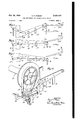
- FIG. l is afragmentary side elevational view of a loom equipped with the mechanism of the invention, many of the conventional features of the loom being omitted;
- Fig. 2 is a fragmentary front elevational view of the loom shown in Fig. 1;
- Fig. 4 is a sectional view on the line 4--4 of Fig. 3;
- Figs. 5, 6 and '7 are side elevational views showing different positions of the box motion lever; and Fig. 8 is a view in perspective showing the friction left-off mechanism and the means for re leasing it.
- the loom shown in the drawings comprises the'usual sides l0, between which extends a shaft 1 l carrying the cloth take-up or sand roll it.
- a ratchet wheel I3 is mounted rigidly on the shaft I I beyond one of the sides and lies between the parts I4a, Nb of a lever I4 pivoted on shaft II.
- a pawl 15 is rigidly mounted on a pin it extending through openings in the two parts of the lever and a spring I! wound about pin it bears at one end against/the pawl and, at the other end, against a pin [8 attached to part Ma of the lever.
- the spring ll tends to hold the end of the pawl out of contact with the teeth of ratchet wheel i3.
- the pin Hii's provided with an arm [8, to which is attached one end of a coil spring 19 connected at its other end to one arm 20a of a bell crank 20 pivoted on one of the loom sides.
- the lever I4 is connected by a link 2! to a pin 22 lying within a-slot i'n a bracket 23 at tached to one of the swords 24 of the lay of the loom. As the lay is oscillated during loom operation, lever I4 is continuously rocked in synchronism with the lay. The length of the rocking movement of lever I4 may be regulated by adjusting the position of pin 22 in the slot in bracket 23.
- the weaving proceeds in the usual Way until a fabric unit, such as a towel, is completed.
- the box motion lever 25 is moved to shift the empty shuttle box to operative position.
- the box motion lever acts through bell crank 20 to move pawl l5 into engagement with ratchet wheel l3.
- the box motion lever acts to remove the tension on the friction bands 33 and thus release the friction let-off mechanism.
- each forward movement of the lay causes the pawl I5 to advance the ratchet wheel 13 and the sand roll.
- the amount of take-up corresponding to a step in the advance of the roll by ratchet wheel I3 is much greater than the take-up per pick in the normal operation of the sand roll. Accordingly, only a few cycles of loom operation are required to produce a weft-less section of substantial length as, for example, a section 2" long may be produced with four picks of the loom, whereas, without the use of the new mechanism, it might be necessary for the loom to operate for 104 picks to produce a section of that length.
- the box motion lever is moved under the control of the pattern chain to shift one of the boxes containing a full shuttle into operative position and the weaving then proceeds in the usual way, until another fringe section is to be formed.
- the mechanism acts to release the friction let-oil mechanism on the ground warp beam only, since the pile warp yarns are under relatively slack tension.
- the friction let-off mechanism on all beams carrying yarns under heavy tension is released during the formation of the fringe.
- a cloth take-up roll having an oscillating lay
- a ratchet wheel fast on the shaft of the roll
- a pawl mounted for rocking movement and movable to engage the Wheel and advance the wheel and roll upon being rocked, the pawl being normally out of engagement with the wheel
- means connecting the pawl to the lay to be continuously rocked thereby means including a box motion lever for shifting the positions of the shuttle boxes, means for moving the pawl to cause it to engage the wheel, and means connected to the box motion lever for releasing the let-off mechanism, the moving and releasing means being actuated by the shifting means, when the latter moves a selected shuttle box to operative position.
Description
Feb. 24, 1953 s. P. PARKER LOOM ATTACHMENT FOR PRODUCTION OF FRINGE 2 SI-IEETS--SI-[EET 1 Filed Nov. 7, 1950 Sail 3 52M BY gmw ma m s,
ATTORNEYS Feb. 24, 1953 s. P. PARKER LOOM ATTACHMENT FOR PRODUCTION OF FRINGE 2 SHEETS SHEET 2 Filed Nov. 7, 1950 ATTORNEYS Patented Feb. 24, 1953 LOOM ATTACHMENT FOR PRODUCTION OF FRINGE Samuel P. Parker, La Grange, Ga., assignor to Callaway Mills Company, La Grange, Ga., a corporation of Georgia Application November 7, 1950, Serial No. 194,553
8 Claims.
This invention relates to looms for weaving units of fabric separated by sections containing warp yarns only, which are later severed to free the units from one another. A terry loom operating in the manner described may be used in the production of individual towels, in which event the sections without filling may be of such length, that, when out midway between the towels, the warp threads of the sections provide a fringe at each end of each towel. More particularly, the invention is concerned with novel means for use with a box loom for modifying the action of the loom so that a section devoid of filling may be produced in a short time and with few loom operations. The new mechanism may be employed on box looms for various purposes but, since its use on terry looms producing fringed towel is particularly advantageous, a form of the mechanism for that purpose will be illustrated and described in detail for purposes of explanation.
Heretoiore, in the weaving of individual towels having a fringe at each end on a terry loom, it has been the practice to complete each towel and then run the loom in the ordinary way with the take-up operating at the regular speed, but with an empty shuttle. As the loom may operate at the rate of 52 picks to the inch and the fringe section between adjacent towels may be 2" long, the loom must operate through 104 cycles to produce such a section. Operation of the loom in this manner is highly uneconomical and attempts have been made heretofore to provide means for speeding up the loom take-up during the production of the fringe and, at the same time, releasing the left-off mechanism, so that undue strain will not be placed upon the warp yarns as a result of the higher rate of take-up. So far as I am aware, the mechanisms heretofore devised for the purpose have not been entirely satisfactory, either because of their complexity or for other reasons.
The present invention is, accordingly, directed to a novel mechanism for use on a loom for increasing the speed at which a section without filling may be produced, and the new mechanism is simple and reliable in operation and it may be applied without diiiiculty to conventional box looms.
The mechanism of the invention includes a ratchet wheel attached to the cloth take-up or sand roll to rotate therewith and a pawl engageable with the ratchet wheel, although normally out of contact therewith. The pawl is mounted for rocking movement and is rocked in synchronism with the lay, as by being connected to the lay. Whenever a section without filling is to be produced, the box motion of the loom shifts a box containing an empty shuttle into operative position and this action of the box motion is employed to move the pawl into engagement with the ratchet wheel and, at the same time, release the friction let-off mechanism controlling the warp beam. The advance of the ratchet wheel and take-up roll by the pawl is much more rapid than the usual advance with the result that only a few cycles of loom operation are re quired to produce a weft-less section of substantial length. When the section is completed, the box motion shifts another shuttle box into position and this action render the pawl inoperative and restores the let-off mechanism to normal operation.
For a better understanding of the invention, reference may be made to the accompanying drawings, in which Fig. l is afragmentary side elevational view of a loom equipped with the mechanism of the invention, many of the conventional features of the loom being omitted;
Fig. 2 is a fragmentary front elevational view of the loom shown in Fig. 1;
Fig. 3 is a sectional view on the line 3-3 of Fig. 1;
Fig. 4 is a sectional view on the line 4--4 of Fig. 3;
Figs. 5, 6 and '7 are side elevational views showing different positions of the box motion lever; and Fig. 8 is a view in perspective showing the friction left-off mechanism and the means for re leasing it.
The loom shown in the drawings comprises the'usual sides l0, between which extends a shaft 1 l carrying the cloth take-up or sand roll it. A ratchet wheel I3 is mounted rigidly on the shaft I I beyond one of the sides and lies between the parts I4a, Nb of a lever I4 pivoted on shaft II. A pawl 15 is rigidly mounted on a pin it extending through openings in the two parts of the lever and a spring I! wound about pin it bears at one end against/the pawl and, at the other end, against a pin [8 attached to part Ma of the lever. The spring ll tends to hold the end of the pawl out of contact with the teeth of ratchet wheel i3. The pin Hii's provided with an arm [8, to which is attached one end of a coil spring 19 connected at its other end to one arm 20a of a bell crank 20 pivoted on one of the loom sides. The lever I4 is connected by a link 2! to a pin 22 lying within a-slot i'n a bracket 23 at tached to one of the swords 24 of the lay of the loom. As the lay is oscillated during loom operation, lever I4 is continuously rocked in synchronism with the lay. The length of the rocking movement of lever I4 may be regulated by adjusting the position of pin 22 in the slot in bracket 23.
The loom is equipped with a conventional box motion and the shuttle boxes are shifted alternatively into operative position by means of a box motion lever 25 actuated by the usual levers 2B, 21 operated by cams under the control of a pattern chain. As shown in Figs. -7, inc., the box motion lever 25 is moved to different positions by levers 26, 2! as determined by the cams and, in each position of lever 25, a different shuttle box is in operative position. In the loom, with which the new mechanism is employed, the third shuttle box contains an empty shuttle and this box is put in operative position by a movement of lever 25 to a position, in which its right-hand end 255a (Fig. 5) is raised and its weighted lefthand end 251) is lowered. An arm 28 pivotally attached to end 25a of lever 25 is connected through rod 29 to the usual box lifter rod and the upper end of rod 29 lies beneath the second arm 29b of bell crank 2H. When the box motion lever 25 is moved to place the shuttle box containing the empty shuttle in operative position, the upper end of rod 29 engages arm 20b of bell crank 20 and swings the bell crank clockwise. Arm 28a of the bell crank then acts through spring E9 to move pawl [5 into engagement with a tooth on ratchet wheel l3, so that, on the forward movement of the lay, the ratchet wheel and the cloth take-up roll are advanced.
The loom includes a support for one or more warp beams 3:), each of which is provided with a friction let-off mechanism. This mechanism includes a brake drum 3| on each flange 32 of the beam and a friction band 33 wrappedv around each drum and having one end attached by hook fi l to a bracket 35 secured to the adjacent loom side. The other end of band 33 is connected to one end of a lever 38, which is pivoted on the bracket 35 and is connected at its other end by a link 3'! to the short arm of a lever 38 pivoted on a bracket 39 attached to the floor. The long arm of lever 38 carries a weight 49, which normally acts through the levers and link to apply tension to band 33 and make it grip its drum 3!. A lever 4| mounted on one of the loom sides is pivotally connected at one end to the box motion lever 25 adjacent its Weighted end and the other end of lever 4! is connected by a hook 42 to one end of an arm 43 fast on a shaft 44 extending across the loom and mounted in brackets 35 at opposite sides thereof. One end of lever 43 overlies lever 36 adjacent link 31 and, when the box motion lever 25 moves to a position to shift the box containing the empty shuttle into operative position, lever 4| is swung and in turn swings lever 43 to rock lever 35 to release the tension on friction band 33. Shaft 44 carries an arm adjacent the other flange of beam 30, which acts in the same way as lever 4| to release the tension on the friction band acting on the drum on that hangs.
In the operation of the loom equipped with the new fringe-forming mechanism, the weaving proceeds in the usual Way until a fabric unit, such as a towel, is completed. Thereafter, under the control of the pattern chain, the box motion lever 25 is moved to shift the empty shuttle box to operative position. In this movement of the box motion lever, it acts through bell crank 20 to move pawl l5 into engagement with ratchet wheel l3. At the same time, the box motion lever acts to remove the tension on the friction bands 33 and thus release the friction let-off mechanism. As the loom continues to operate, each forward movement of the lay causes the pawl I5 to advance the ratchet wheel 13 and the sand roll. The amount of take-up corresponding to a step in the advance of the roll by ratchet wheel I3 is much greater than the take-up per pick in the normal operation of the sand roll. Accordingly, only a few cycles of loom operation are required to produce a weft-less section of substantial length as, for example, a section 2" long may be produced with four picks of the loom, whereas, without the use of the new mechanism, it might be necessary for the loom to operate for 104 picks to produce a section of that length. When the fringe section has been completed, the box motion lever is moved under the control of the pattern chain to shift one of the boxes containing a full shuttle into operative position and the weaving then proceeds in the usual way, until another fringe section is to be formed.
In the use of the new mechanism with a terry loom, the mechanism acts to release the friction let-oil mechanism on the ground warp beam only, since the pile warp yarns are under relatively slack tension. In other looms, the friction let-off mechanism on all beams carrying yarns under heavy tension is released during the formation of the fringe.
I claim:
1. In a loom having an oscillating lay, a plurality 0f shuttle boxes movable alternatively to operative position, and a warp beam controlled by friction let-off mechanism, the combination of a cloth take-up roll, a ratchet wheel fast on the shaft of the roll, a pawl mounted for rocking movement and movable to engage the wheel and advance the wheel and roll upcn being rocked. the pawl being normally out of engagement with the wheel, means connected to the lay for continuously rocking the pawl with the lay, means including a box motion lever for shifting the positions of the shuttle boxes, means for moving the pawl to cause it to engage the wheel, and means connected to the box motion lever for releasing the let-off mechanism, the moving and releasing means being actuated by the shifting means, when the latter moves a selected shuttle box to operative position.
2. In a loom having an oscillating lay, a plurality of shuttle boxes movable alternatively to operative position, and a warp beam controlled by friction let-off mechanism, the combination of a cloth take-up roll, a ratchet wheel fast on the shaft of the roll, a pawl mounted for rocking movement and movable to engage the Wheel and advance the wheel and roll upon being rocked, the pawl being normally out of engagement with the wheel, means connecting the pawl to the lay to be continuously rocked thereby, means including a box motion lever for shifting the positions of the shuttle boxes, means for moving the pawl to cause it to engage the wheel, and means connected to the box motion lever for releasing the let-off mechanism, the moving and releasing means being actuated by the shifting means, when the latter moves a selected shuttle box to operative position.
3. In a loom having an oscillating lay, a plurality of shuttle boxes movable alternatively to operative position, and a warp beam controlled by friction let-off mechanism, the combination of a cloth take-up roll, a ratchet wheel fast on the shaft of the roll, a lever mounted adjacent the ratchet wheel and connected to the lay to be continuously rocked thereby, a pawl mounted on the lever and movable into engagement with the wheel to advance the wheel and roll as the lever is rocked, the pawl being normally out of contact with the wheel, means including a box motion lever for shifting the positions of the shuttle boxes, means for moving the pawl into engagement with the wheel, and means connected to the box motion lever for releasing the let-off mechanism, the moving and releasing means being actuated by the shifting means, when the latter moves a selected shuttle box to operative position.
4. In a loom having an oscillating lay, a plurality of shuttle boxes movable alternatively to operative position, and a warp beam controlled by friction let-off mechanism, the combination of a cloth take-up roll, a ratchet wheel fast on the shaft of the roll, a pawl mounted for rocking movement and movable to engage the Wheel and advance the wheel and roll upon being rocked, the pawl being normally out of engagement with the wheel, means connecting the pawl to the lay to be continuously rocked thereby, saidv means being adjustable to vary the length of the rocking movement of the pawl, means including a box motion lever for shifting the positions of the shuttle boxes, means for moving the pawl to cause it to engage the wheel, and means connected to the box motion lever for releasing the let-off mechanism, the moving and releasing means being actuated by the shifting means, when the latter moves a selected shuttle box to operative position.
5. In a loom having an oscillating lay, a plurality of shuttle boxes movable alternatively to operative position, and a warp beam controlled 5 by friction let-off mechanism, the combination of a cloth take-up roll, a ratchet wheel fast on the shaft of the roll to rotate therewith, a lever mounted adjacent the roll, a connection between the lever and the lay causing the lever to swing continuously with the lay, a pawl mounted on the lever and engageable with the ratchet wheel to advance the wheel and roll, when the lever is swung in one direction, spring means biasing the pawl to inoperative position, means including a box motion lever for shifting the positions of the shuttle boxes, means for moving the pawl to cause it to engage the ratchet wheel, and means connected to the box motion lever for releasing the let-off mechanism, the moving and releasing means being actuated by the shifting means, when the latter moves a selected shuttle box to operative position.
6. In a loom having an oscillating lay, a plurality of shuttle boxes movable alternatively to operative position, and a warp beam controlled by friction let-off mechanism, the combination of a cloth take-up roll, a ratchet wheel fast on the shaft of the roll to rotate therewith, a lever mounted adjacent the roll, a connection between the lever and the lay causing the lever to swing continuously with the lay, a pawl mounted on the lever and engageable with the ratchet wheel to advance the wheel and roll, when the lever is swung in one direction, spring means biasing the pawl to inoperative position, means, including a box motion lever, for shifting the positions of the shuttle boxes, means including a pivoted element connected to the pawl and rockable to move the pawl to cause it to engage the ratchet wheel, and means connected to the box motion lever for releasing the let-ofl mechanism, the pivoted element being rocked by the shifting means and the releasing means being actuated by the box motion lever, when the shifting means moves a selected shuttle box to operative position.
7. In a loom having an oscillating lay, a plurality of shuttle boxes movable alternatively to operative position, and a warp beam controlled by friction let-off mechanism, the combination of a cloth take-up roll, a ratchet wheel fast on the shaft of the roll to rotate therewith, a lever mounted adjacent the roll, a connection between the lever and the lay causing the lever to swing continuously with the lay, a pawl mounted on the lever and engageable with the ratchet wheel to advance the wheel and roll, when the lever is swung in one direction, means biasing the pawl to inoperative position, means, including a box motion lever, for shifting the positions of the shuttle boxes, means for moving the pawl to cause it to engage the ratchet wheel, and linkage connected to the box motion lever and operable to release the let-off mechanism, the moving means and linkage being actuated by the shifting means, when the latter moves a selected shuttle box to operative position.
8. In a loom having an oscillating lay, a plurality of shuttle boxes movable alternatively to operative position, and a warp beam controlled by friction let-01f mechanism, the combination of a cloth take-up roll, a ratchet wheel fast on the shaft of the roll to rotate therewith, a lever pivoted on the axis of the roll, a direct connection between the lever and the lay causing the lever to swing continuously with the lay, a pawl pivoted on the lever and adapted to swing toengage the ratchet wheel and advance the wheel and roll, as the lever swings in one direction, a spring biasing the pawl to inoperative position relative to the ratchet wheel, means, including a box motion lever, for shifting the positions of the shuttle boxes, means for swinging the pawl against the resistance of the spring into engagement with the ratchet Wheel, and linkage connected to the box motion lever and operable to release the let-off mechanism, the pawl swinging means and the linkage being actuated by the shifting means, when the latter moves a selected shuttle box to operative position.
SAMUEL P. PARKER.
REFERENCES CITED The following references are of record in the file of this patent:
UNITED STATES PATENTS Number Name Date 427,270 Riddiough May 6, 1890 492,144 Cox Feb. 21, 1893 544,703 Wattie Aug. 20, 1895 782,061 Rothwell Feb. 7, 1905 791,487 McPeak June 6, 1905 2,352,341 Ott June 27, 1944
Priority Applications (1)
| Application Number | Priority Date | Filing Date | Title |
|---|---|---|---|
| US194553A US2629404A (en) | 1950-11-07 | 1950-11-07 | Loom attachment for production of fringe |
Applications Claiming Priority (1)
| Application Number | Priority Date | Filing Date | Title |
|---|---|---|---|
| US194553A US2629404A (en) | 1950-11-07 | 1950-11-07 | Loom attachment for production of fringe |
Publications (1)
| Publication Number | Publication Date |
|---|---|
| US2629404A true US2629404A (en) | 1953-02-24 |
Family
ID=22718033
Family Applications (1)
| Application Number | Title | Priority Date | Filing Date |
|---|---|---|---|
| US194553A Expired - Lifetime US2629404A (en) | 1950-11-07 | 1950-11-07 | Loom attachment for production of fringe |
Country Status (1)
| Country | Link |
|---|---|
| US (1) | US2629404A (en) |
Cited By (1)
| Publication number | Priority date | Publication date | Assignee | Title |
|---|---|---|---|---|
| US3516449A (en) * | 1968-08-27 | 1970-06-23 | Crompton & Knowles Corp | Fringe forming mechanism for looms |
Citations (6)
| Publication number | Priority date | Publication date | Assignee | Title |
|---|---|---|---|---|
| US427270A (en) * | 1890-05-06 | Take-up mechanism for looms | ||
| US492144A (en) * | 1893-02-21 | The nohris peters co | ||
| US544703A (en) * | 1895-08-20 | wattie | ||
| US782061A (en) * | 1903-04-01 | 1905-02-07 | W H & A E Margerison & Company | Fringe-pulling mechanism for looms. |
| US791487A (en) * | 1905-03-17 | 1905-06-06 | Patrick Mcpeak | Fringe-pulling mechanism for looms. |
| US2352341A (en) * | 1940-11-04 | 1944-06-27 | Callaway Mills | Loom |
-
1950
- 1950-11-07 US US194553A patent/US2629404A/en not_active Expired - Lifetime
Patent Citations (6)
| Publication number | Priority date | Publication date | Assignee | Title |
|---|---|---|---|---|
| US427270A (en) * | 1890-05-06 | Take-up mechanism for looms | ||
| US492144A (en) * | 1893-02-21 | The nohris peters co | ||
| US544703A (en) * | 1895-08-20 | wattie | ||
| US782061A (en) * | 1903-04-01 | 1905-02-07 | W H & A E Margerison & Company | Fringe-pulling mechanism for looms. |
| US791487A (en) * | 1905-03-17 | 1905-06-06 | Patrick Mcpeak | Fringe-pulling mechanism for looms. |
| US2352341A (en) * | 1940-11-04 | 1944-06-27 | Callaway Mills | Loom |
Cited By (1)
| Publication number | Priority date | Publication date | Assignee | Title |
|---|---|---|---|---|
| US3516449A (en) * | 1968-08-27 | 1970-06-23 | Crompton & Knowles Corp | Fringe forming mechanism for looms |
Similar Documents
| Publication | Publication Date | Title |
|---|---|---|
| US2625956A (en) | Loop warp tension-variable beat-up apparatus for terry looms | |
| US2352341A (en) | Loom | |
| US2629404A (en) | Loom attachment for production of fringe | |
| US3160177A (en) | Irregular warp feed mechanism | |
| US2425781A (en) | Cloth roll mechanism for looms | |
| US1665274A (en) | Attachement for looms | |
| US2755822A (en) | Resistance let-offs | |
| US1901769A (en) | Loom | |
| US3351096A (en) | Terry loom with fell shifting means | |
| US2946352A (en) | Loom let-off mechanism | |
| US3920052A (en) | Terry warp feeding apparatus | |
| US2610652A (en) | Pile fabric loom | |
| US3746052A (en) | Method and apparatus for feeding terry warps in looms | |
| US1747883A (en) | Crossbar and open-weave loom | |
| US2170762A (en) | Let-off mechanism for looms | |
| US3366146A (en) | Fringe forming mechanism for looms | |
| US628206A (en) | Loom. | |
| US1526990A (en) | Loom | |
| US1044226A (en) | Fringe-loom. | |
| US710024A (en) | Let-off-arresting mechanism for looms. | |
| US829689A (en) | Let-off mechanism for looms. | |
| US2044440A (en) | Loom for weaving crinkle cloth | |
| US1582526A (en) | Loom | |
| US1659236A (en) | Let-off for looms | |
| US2065731A (en) | Electric warp stop motion for terry towel looms |