US2629240A - Yarn changing means for circular knitting machines - Google Patents
Yarn changing means for circular knitting machines Download PDFInfo
- Publication number
- US2629240A US2629240A US143060A US14306050A US2629240A US 2629240 A US2629240 A US 2629240A US 143060 A US143060 A US 143060A US 14306050 A US14306050 A US 14306050A US 2629240 A US2629240 A US 2629240A
- Authority
- US
- United States
- Prior art keywords
- yarn
- circular knitting
- arm
- cam
- feeds
- Prior art date
- Legal status (The legal status is an assumption and is not a legal conclusion. Google has not performed a legal analysis and makes no representation as to the accuracy of the status listed.)
- Expired - Lifetime
Links
Images


Classifications
-
- D—TEXTILES; PAPER
- D04—BRAIDING; LACE-MAKING; KNITTING; TRIMMINGS; NON-WOVEN FABRICS
- D04B—KNITTING
- D04B15/00—Details of, or auxiliary devices incorporated in, weft knitting machines, restricted to machines of this kind
- D04B15/38—Devices for supplying, feeding, or guiding threads to needles
- D04B15/54—Thread guides
- D04B15/58—Thread guides for circular knitting machines; Thread-changing devices
- D04B15/60—Thread guides for circular knitting machines; Thread-changing devices with thread-clamping or -severing devices
-
- D—TEXTILES; PAPER
- D04—BRAIDING; LACE-MAKING; KNITTING; TRIMMINGS; NON-WOVEN FABRICS
- D04B—KNITTING
- D04B9/00—Circular knitting machines with independently-movable needles
- D04B9/26—Circular knitting machines with independently-movable needles for producing patterned fabrics
- D04B9/28—Circular knitting machines with independently-movable needles for producing patterned fabrics with colour patterns
Definitions
- My invention relates to knitting and relates particularly to knitting on a sinker top circular knitting machine such as the H. Brinton Company Selective striping machine, style SS.
- My invention is specifically employed to alternate the feeding of different colored yarns to knitting needles without altering the speed of the knitting machine.
- My invention embodies a pattern controlled yarn changer wherein a plurality of movable yarn-feeding members are actuated by pre-arranged pattern mechanisms for changing the yarn supply to the needles of the machine.
- Another object of my invention is to provide a circular knitting machine wherein numerous color combinations may be knitted together to form an attractively colored fabric.
- Another object of my invention is to increase the productive capacity of a circular knitting machine where difierent color combinations are employed.
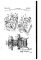
- Fig. 1 is a perspective view of a circular knitting machine embodying my invention.
- Fig. 2 is a perspective view of my yarn changer wherein a yarn is in each changer but wherein one yarn is used to be knitted to form the fabric whereas the other yarn is held in an idle position.
- Fig. 3 is a perspective view of the yarn changer wherein the yarn used in knitting in Fig. 2 has been cast out of knitting position and a new yarn substituted.
- Fig. 4 is a side view showing the yarn changer and a side view of part of the pattern mechanism.
- Fig. 5 is a rear view'of apart of the pattern mechanism.
- Fig. 6 is a top view of the pattern mechanism of Fig. 5. 1
- Fig. '7 is a perspective view showing the mechanism for actuating the plungers.
- Fig. 8 is a fragmentary perspective view showing the mechanism for actuating a pair of cylindrical rods or plungers.
- Fig. 9 is a fragmentary view which shows the pattern generally for controlling the cams which elevate or lower the cylinder knitting needles.
- FIG. 1 a circular knitting machine of the S. S. style of selective striping machine manufactured by the H. Brinton Company.
- This invention may be suitably adapted to machines of the same class that are manufactured by manufacturers other than Brinton.
- the circular knitting machine comprises a base assembly I 0, a pattern mechanism l2, a fabric take-up tension assembly M, cylinder and dial plate assembly l6, a head and cam ring assembly l8, and a motor driven assembly 20.
- a cylinder is mounted upon a gear ring, which is driven in the customary manner and rotatably carried to a bed plate, and a dial is mounted in the well-known manner and driven in unison with the needle cylinder.
- the yarn changing means or striping unit generally designated as A, is carried upon a single bracket 22, having a vertical arm 22A, fixedly mounted upon the bed plate 24.
- a table holding the yarn, generally designated as B, which usually is able to accommodate thirty-two cones is enlarged to hold sixty-four cones.
- tension devices, guides, etc. which will not be described in detail.
- the striping unit or yarn changer comprises a pair of yarn feeds 26, 28, mounted upon the same horizontally located pivot 30, which is carried by the vertical arm 22A of the bracket 22.
- the yarn carrying arm 28 has a small opening or eye 28A at its lower end through which one colored yarn B is threaded and it has integrally formed therewith a shorter cam-like arm 283 which is the actuating arm for the yarn feeder arm 28.
- the arm. 28B interfitszwithaibifurcated. end 32A ofthe pivoted cam bell-cranklever 32.
- the second arm 26 havinganieye. or. opening.
- thexbelljcrankdever 32 isableto move either arm 2.6 or 28 -.toa. predetermined*po-. sition of yarnlaying or yarniidling, Sinceboth arms work reciprocally. one .must moveyarn into knitting position; as the other. moves; into idling position. When one yarn changer arm moves the other arm moves in unison .and.the limitingin movement is limited .by a-stop pin.35.-.
- the particular yarn B which is to belaidzupon theneedle is. controlled. by; a pattern mechanism l2..
- the plungers 36; 33 are independently controlled .as. contrasted to the plungers 40, 42.which;are. also:attached to a pattern mechanism.for;controlling;the striping cams; The striping cams.- are'.
- This continuous knitting operation isbrought aboutflby keeping the cylinderzneedles elevated with the. raised'cam .and i'transferring color yarn only by theyarn. feed.
- The. importance;of having independent yarn feed” mechanism control and independent needle elevating control is that greater productivity is obtained as contrasted to a single yarn feed and needle elevating control.
- the needles where independent controls are employed need not be taken outcof knittingpositionwhenthereis ,a changeover. from one. yarn feedlto; another yarn feed. If a single control for both the yarn feeds and the needle elevating mechanism were used then the needles would have to be taken out of knittin position when-the change is made from one yarn to another yarn.
- theineedleslare By idling the needles is meanttheineedleslare not raised to take additional .yarnandtretain the stitch they hold.
- a foot piece MA on a rod .44 rests uponthe links of a separate pattern chain mountedon a member 43 so that high, low-,.or neutral links elevate the rod 44 that is pivotally connected to at link 46.
- the other end of the. link..46 .is...p ivotally. connected to one end of.a.lever.48 thatisrigidly amxed to'a shaftlifl.
- a second .lever 52 having one. endrigidlyaffixed. to the shaft .59 rotates 0r 'oscillates in .unisonwith the-.shaft.50 and. the lever 48.
- Theother end of the second'lever 52 is pivoted at .51 to an intermediatelever 51Athat isalso pivoted'to a cross pintfl... ThGgCI'OSS pin 6.0 extends at right anglesto. the intermediate; lever 51A but both movein unisonupwardlyand.downwardly.
- One endiof thecrosspin fifljispivotally connected at58 to amember.5'4 ,andthe.other end of the cross pin 60 is pivotally connected to a second member 54A which is. similar in. construction and. function asthe member54.
- the member;54A has plunger 36..pivo.tally connectedv at the upper endthereof atiifiALand.
- the member.:54A oscillates about a pivot 576., The pivot;36A,is;above the pivot'56. It should benoted that aipull downwardly on the rodfill'oscillates'the member 54A about the pivot 55therebyp1111ing the plunger 35 out-of'action; On .the other hand when the rod is moved upwardly the member 54A oscillates about the pivot 56 pushingtheplunger36 into' action whereby it will be engaged. by thesurface'32C of the bell crank lever 32.
- the plunger 33 is pivotally connected at 38A below the pivot 56 of the member 54 so that a pull downwardly on the rod 50 causes the. pivotal connection at 58 to'oscillatedownwardly. about the pivot 56 so that the plunger 38 moves into a position to engage the surface 32D. of the bell. crank lever32. A movement upwardly'of the rod-'60 causes the'plunger 38 to be pulled out of .action.
- a movementupwardly'ofthe rod causes the. plunger 36 to be moved" into action andlthe plunger '38 pulled-out of action simultaneously.
- A" second independent-pattern chain 63' (Fig. '7) of conventional construction engages a foot piece 63A on a-pivotedlever63BJ
- the movable end of. the .lever'"63B" has"avertical link '64 attached theretoand".
- a; second link-BSwh'ich is pivotedto:the-horizontal'linkrfl at HI.
- the free end of.the link 66 ispivotedto'a striplZ'which is pivoted at" 68 so that movement of the strip 12 .idles oneor'th'e other of theplimgers 49, 42, each'of which ispivotally'attached- Theplungers 40, 42 elevate or depress the cams which raise or lower the cylinder knitting needles.
- the plungers w; 42' move radially of the. needle cylinder and one or the other of the plungers 48, 42 is adapted to be in the path of the converging surfaces so that the tuck cam arm may oscillate.
- the plungers 36, 38 likewise move radially of the needle cylinder and one or the other may be abutted or engaged by the cam surfaces 32C or 32D to oscillate the cam arm 32.
- a sinker top circular knitting machine having a plurality of knitting needles, a plurality of striping units, each striping unit having a pair of yarn feeds wherein each of said yarn feeds are synchronously actuated whereby only one yarn feed supplies yarn to said needles at one time and the second yarn feed is idle, a pivoted cam having a forked arm, one of said yarn feeds having an arm interfitting with said forked arm of said cam whereby the movement of said cam actuates the yarn feed either to yarn feeding or yarn idling position, and means connected to said cam to actuate a second feed to the converse positions of the other yarn feed.
- each striping unit having a pair of yarn feeds wherein each of said yarn feeds are synchronously actuated whereby only one yarn feed supplies yarn to said needles at one time and the other yarn feed is idle, a pivoted cam having a forked arm at one end thereof, one of said yarn feeds having an arm interfitting with said forked arm of said cam whereby the movement of said cam actuates the yarn feed either to yarn feeding or yarn idling position, means connected to said cam to actuate a second feed to the converse positions of the other yarn feed, and means to actuate said cam to control one yarn feed and idle the other feed.
Description
Feb. 24, 1953 E. LEADERMAN YARN CHANGING MEANS FOR CIRCULAR KNITTING MACHINES Filed Feb. 8, 1950 5 Sheets-Sheet l ZSrwemtor 3 EAHLELE AD ERMKN Z 2 (Ittomeg EA'RLELE ADERMAN Z attorney 5 Sheets-Sheet 2 A if I A A Twsk MQ Feb. 24, 1953 E LEADERMAN YARN CHANGING MEANS FOR CIRCULAR KNITTING MACHINES Flled Feb 8 1950 3 lwentor (Ittomeg 5 Sheets-Sheet 5 ,zigzio ,155;
EARLELEADERMAN E LEADERMAN YARN CHANGING MEANS FOR CIRCULAR KNITTING MACHINES Feb. 24, 1953 Flled Feb 8 195 N A 0 4 M M M t M R Y E E 9 h V D N 2 m A R 6 S E O 2 a L W e E a H A 5 A E Y B E LEADERMAN YARN CHANGING MEANS FOR CIRCULAR KNITTING MACHINES Feb. 24, 1953 filed Feb 8 1950 m 0 5 4 T 2 t N E ED 9 y W Y a Q m E a t N 2 6 Dn m E O S w 5 A E A E LEADERMAN YARN CHANGING MEANS FOR CIRCULAR KNITTING MACHINES Feb. 24, 1953 filed Feb 8 1950 Patented Feb. 24, 1953 YARN CHANGING MEANS FOR CIRCULAR KNITTING MACHINES Earle Leaderman, Philadelphia, Pa., assignor to Lee-Marc Fabrics, Philadelphia, Pa., a partnership Application February 8, 1950, Serial No. 143,060
4 Claims. (Cl. 66-50) My invention relates to knitting and relates particularly to knitting on a sinker top circular knitting machine such as the H. Brinton Company Selective striping machine, style SS.
My invention is specifically employed to alternate the feeding of different colored yarns to knitting needles without altering the speed of the knitting machine. My invention embodies a pattern controlled yarn changer wherein a plurality of movable yarn-feeding members are actuated by pre-arranged pattern mechanisms for changing the yarn supply to the needles of the machine.
Since the Brinton machine under discussion contains thirty two feeds, the utilization of my invention enables thirty-two feeds of two different colors to be instantly employed when the color of the yarn fed is changed to the other color or vice versa, thereby increasing the production over the prior art devices.
Heretofore, all types of predetermined color combinations could be knitted on the circular knitting machine using only those feeds carrying the desired color. However, with my invention, I have been able to rapidly change yarns without idling as many yarn feeds, thereby maintaining a greater production and obtaining new and novel designs, by inter-changing color combinations among sixty-four cones of yarn instead of thirty-two cones as on prior machines.
It, therefore, is an object of my invention to provide a yarn changer for a circular knitting machine.
It is another object of my invention to provide a yarn changer for a. circular knitting machine wherein the yarn changer will be cam. actuated.
Another object of my invention is to provide a circular knitting machine wherein numerous color combinations may be knitted together to form an attractively colored fabric.
Another object of my invention is to increase the productive capacity of a circular knitting machine where difierent color combinations are employed.
Other objects of my invention are to provide an improved device of the character described, that is easily and economically produced, which is sturdy in construction, and which is highly efiicient in operation. I
With the above and related objects in view, my invention consists in the details of the construction and combination of parts, as will be more fully understood from the following description, when read in conjunction with the accompanying drawings, in which;
Fig. 1 is a perspective view of a circular knitting machine embodying my invention.
Fig. 2 is a perspective view of my yarn changer wherein a yarn is in each changer but wherein one yarn is used to be knitted to form the fabric whereas the other yarn is held in an idle position.
Fig. 3 is a perspective view of the yarn changer wherein the yarn used in knitting in Fig. 2 has been cast out of knitting position and a new yarn substituted.
Fig. 4 is a side view showing the yarn changer and a side view of part of the pattern mechanism.
Fig. 5 is a rear view'of apart of the pattern mechanism.
Fig. 6 is a top view of the pattern mechanism of Fig. 5. 1
Fig. '7 is a perspective view showing the mechanism for actuating the plungers.
Fig. 8 is a fragmentary perspective view showing the mechanism for actuating a pair of cylindrical rods or plungers.
Fig. 9 is a fragmentary view which shows the pattern generally for controlling the cams which elevate or lower the cylinder knitting needles.
Referring now in detail to the drawings wherein similar reference characters refer to similar parts, I show in Fig. 1 a circular knitting machine of the S. S. style of selective striping machine manufactured by the H. Brinton Company. This invention may be suitably adapted to machines of the same class that are manufactured by manufacturers other than Brinton.
The circular knitting machine comprises a base assembly I 0, a pattern mechanism l2, a fabric take-up tension assembly M, cylinder and dial plate assembly l6, a head and cam ring assembly l8, and a motor driven assembly 20.
A cylinder is mounted upon a gear ring, which is driven in the customary manner and rotatably carried to a bed plate, and a dial is mounted in the well-known manner and driven in unison with the needle cylinder. The yarn changing means or striping unit, generally designated as A, is carried upon a single bracket 22, having a vertical arm 22A, fixedly mounted upon the bed plate 24. A table holding the yarn, generally designated as B, which usually is able to accommodate thirty-two cones is enlarged to hold sixty-four cones. There are provided tension devices, guides, etc., which will not be described in detail.
The striping unit or yarn changer comprises a pair of yarn feeds 26, 28, mounted upon the same horizontally located pivot 30, which is carried by the vertical arm 22A of the bracket 22.
3 The yarn carrying arm 28 has a small opening or eye 28A at its lower end through which one colored yarn B is threaded and it has integrally formed therewith a shorter cam-like arm 283 which is the actuating arm for the yarn feeder arm 28. The arm. 28B interfitszwithaibifurcated. end 32A ofthe pivoted cam bell-cranklever 32.
which has an arrow-like cam end defined by two converging surfaces 320 and 32D. The cam arm. 32 is pivoted at 33 so that oscillationofthecam. arm 3213 results in oscillation of'the yarnfeeder.
The second arm 26 havinganieye. or. opening.
26A through which the yarn B passes carries a short pin 253 to which a rigid rod 34 is attached- The other end of the rod 34 is attached at 32E to the arm'32B. of thei-control lever 32; It is" to be noted thatthexbelljcrankdever 32 isableto move either arm 2.6 or 28 -.toa. predetermined*po-. sition of yarnlaying or yarniidling, Sinceboth arms work reciprocally. one .must moveyarn into knitting position; as the other. moves; into idling position. When one yarn changer arm moves the other arm moves in unison .and.the limitingin movement is limited .by a-stop pin.35.-.
The particular yarn B which is to belaidzupon theneedle is. controlled. by; a pattern mechanism l2..
A pair of cylindrical.rods=;or.-plungers: 35', 38 controlled by the pattern mechanism are adapted to engagezatflifirent.times, the surfaces '32Ctand 32D of the lever 32, respectively. The plungers 36; 33 are independently controlled .as. contrasted to the plungers 40, 42.which;are. also:attached to a pattern mechanism.for;controlling;the striping cams; The striping cams.- are'. located beneath the platform 24 and are adaptedtoengage the knitting needles; generally designated as'N; By the use ofthe independent controls-.forthe striping cams and for the-knitting ortucking-cams, a greater versatility :ofithe: use of themachine can be obtained.
It isto be noted that inthe prior art machines where two-colors :were. used on the feeds that in athirty-two feed machines that only sixteen feeds could be used at.one -time,- whereas in my inventionliam able-to-use:thirty-two feeds of the same color so that greater production .can be achieved on a machine embodyingmy inventicn than with machines of.-.the prior art... I .also providean independentstripingv control. so that themachine hasa greater versatility..
In the prior. art a single. patterncha-in was used to control the cam which elevates or. lowers .the cylinder knitting needles... as. well as. the yarn feeds... This resulted in acycleof events wherein.
the. yarn. idling occurredlata time the; needle cams were lowered out .ofjaction with the result noknitting Was performed. However. with .my invention,- embodied in .asinkertop circular knitting machine I- utilize .a-separate ,pattern .chain forthe yarn feeding andaseparate pattern chain for. controlling the cams which .elevate ,or. lower the cylinderknittingneedles... Theyarn feeding and. knitting operationscontinue even duringthe interval of .time. when .the .yarn...ch'anging action comes into play.
This continuous knitting operation: isbrought aboutflby keeping the cylinderzneedles elevated with the. raised'cam .and i'transferring color yarn only by theyarn. feed. The. importance;of having independent yarn feed" mechanism control and independent needle elevating control is that greater productivity is obtained as contrasted to a single yarn feed and needle elevating control.
The reason being that the needles where independent controls are employed need not be taken outcof knittingpositionwhenthereis ,a changeover. from one. yarn feedlto; another yarn feed. If a single control for both the yarn feeds and the needle elevating mechanism were used then the needles would have to be taken out of knittin position when-the change is made from one yarn to another yarn. By idling the needles is meanttheineedleslare not raised to take additional .yarnandtretain the stitch they hold.
It is to be noticed that a foot piece MA on a rod .44 rests uponthe links of a separate pattern chain mountedon a member 43 so that high, low-,.or neutral links elevate the rod 44 that is pivotally connected to at link 46. The other end of the. link..46 .is...p ivotally. connected to one end of.a.lever.48 thatisrigidly amxed to'a shaftlifl. A second .lever 52, having one. endrigidlyaffixed. to the shaft .59 rotates 0r 'oscillates in .unisonwith the-.shaft.50 and. the lever 48. Theother end of the second'lever 52 is pivoted at .51 to an intermediatelever 51Athat isalso pivoted'to a cross pintfl... ThGgCI'OSS pin 6.0 extends at right anglesto. the intermediate; lever 51A but both movein unisonupwardlyand.downwardly. One endiof thecrosspin fifljispivotally connected at58 to amember.5'4 ,andthe.other end of the cross pin 60 is pivotally connected to a second member 54A which is. similar in. construction and. function asthe member54. The member;54A has plunger 36..pivo.tally connectedv at the upper endthereof atiifiALand. the member.:54A oscillates about a pivot 576., The pivot;36A,is;above the pivot'56. It should benoted that aipull downwardly on the rodfill'oscillates'the member 54A about the pivot 55therebyp1111ing the plunger 35 out-of'action; On .the other hand when the rod is moved upwardly the member 54A oscillates about the pivot 56 pushingtheplunger36 into' action whereby it will be engaged. by thesurface'32C of the bell crank lever 32. The plunger 33 is pivotally connected at 38A below the pivot 56 of the member 54 so that a pull downwardly on the rod 50 causes the. pivotal connection at 58 to'oscillatedownwardly. about the pivot 56 so that the plunger 38 moves into a position to engage the surface 32D. of the bell. crank lever32. A movement upwardly'of the rod-'60 causes the'plunger 38 to be pulled out of .action.
It is'observed that the *rod'fifl moves the members 5454A simultaneously about the pivots "53,
56 and thata movement-downwardly of the rod 60 pulls the;.upp.er'plunger 36 out of action-and moves thelowerplunger38 intoaction simultaneously. A movementupwardly'ofthe rod (it! causes the. plunger 36 to be moved" into action andlthe plunger '38 pulled-out of action simultaneously.
A" second independent-pattern chain 63' (Fig. '7) of conventional construction engages a foot piece 63A on a-pivotedlever63BJ The movable end of. the .lever'"63B"has"avertical link '64 attached theretoand". a; second link-BSwh'ich is pivotedto:the-horizontal'linkrfl at HI. The free end of.the link 66 ispivotedto'a striplZ'which is pivoted at" 68 so that movement of the strip 12 .idles oneor'th'e other of theplimgers 49, 42, each'of which ispivotally'attached- Theplungers 40, 42 elevate or depress the cams which raise or lower the cylinder knitting needles.
The plungers w; 42' move radially of the. needle cylinder and one or the other of the plungers 48, 42 is adapted to be in the path of the converging surfaces so that the tuck cam arm may oscillate.
The plungers 36, 38 likewise move radially of the needle cylinder and one or the other may be abutted or engaged by the cam surfaces 32C or 32D to oscillate the cam arm 32.
Although my invention has been described in considerable detail, such description is meant to be illustrative, rather than limiting, as the invention may be variously embodied, and the scope of the invention is to be determined as claimed.
I claim as my invention:
1. In a sinker top circular knitting machine having a plurality of knitting needles, a plurality of striping units, each striping unit having a pair of yarn feeds wherein each of said yarn feeds are synchronously actuated whereby only one yarn feed supplies yarn to said needles at one time and the second yarn feed is idle, a pivoted cam having a forked arm, one of said yarn feeds having an arm interfitting with said forked arm of said cam whereby the movement of said cam actuates the yarn feed either to yarn feeding or yarn idling position, and means connected to said cam to actuate a second feed to the converse positions of the other yarn feed.
2. The invention of claim 1 including a pair of plungers only one of which is in actuating position at any one period of time, said pivoted cam being engageable by one or the other of said plungers to place one of said yarn feeds of each striping unit in yarn feeding position at any one period of time.
3. The invention of claim 1 wherein an independent pattern chain controls the yarn feeds, means to elevate or lower said knitting needles,
and a second independent pattern chain to control the elevating or lowering of said knitting needles at all times.
4. In a sinker top circular knitting machine having a plurality of knitting needles, a plurality of striping units, each striping unit having a pair of yarn feeds wherein each of said yarn feeds are synchronously actuated whereby only one yarn feed supplies yarn to said needles at one time and the other yarn feed is idle, a pivoted cam having a forked arm at one end thereof, one of said yarn feeds having an arm interfitting with said forked arm of said cam whereby the movement of said cam actuates the yarn feed either to yarn feeding or yarn idling position, means connected to said cam to actuate a second feed to the converse positions of the other yarn feed, and means to actuate said cam to control one yarn feed and idle the other feed.
EARLE LEADERMAN.
REFERENCES CITED The following references are of record in the file of this patent:
UNITED STATES PATENTS Number Name Date 383,817 Lamprey et al May 29, 1888 604,640 Scott May 24, 1898 629,503 Hemphill July 25, 1899 761,385 Langer May 31, 1904 1,883,320 Aaronson Oct. 18, 1932 1,883,337 Collar Oct. 18, 1932 1,925,450 Levin Sept. 5, 1933 1,929,125 Steere Oct. 3, 1933 2,059,076 Aaronson Oct. 27, 1936 2,189,276 Agulnek et a1 Feb. 6, 1940
Priority Applications (1)
| Application Number | Priority Date | Filing Date | Title |
|---|---|---|---|
| US143060A US2629240A (en) | 1950-02-08 | 1950-02-08 | Yarn changing means for circular knitting machines |
Applications Claiming Priority (1)
| Application Number | Priority Date | Filing Date | Title |
|---|---|---|---|
| US143060A US2629240A (en) | 1950-02-08 | 1950-02-08 | Yarn changing means for circular knitting machines |
Publications (1)
| Publication Number | Publication Date |
|---|---|
| US2629240A true US2629240A (en) | 1953-02-24 |
Family
ID=22502424
Family Applications (1)
| Application Number | Title | Priority Date | Filing Date |
|---|---|---|---|
| US143060A Expired - Lifetime US2629240A (en) | 1950-02-08 | 1950-02-08 | Yarn changing means for circular knitting machines |
Country Status (1)
| Country | Link |
|---|---|
| US (1) | US2629240A (en) |
Citations (10)
| Publication number | Priority date | Publication date | Assignee | Title |
|---|---|---|---|---|
| US383817A (en) * | 1888-05-29 | lamprey | ||
| US604640A (en) * | 1898-05-24 | Yarn-changing device for rib-knitting machines | ||
| US629503A (en) * | 1898-09-24 | 1899-07-25 | Walter W Radcliffe | Knitting-machine. |
| US761385A (en) * | 1903-10-07 | 1904-05-31 | Felix Lederer | Circular-knitting machine. |
| US1883320A (en) * | 1931-12-12 | 1932-10-18 | Brinton Company H | Yarn cutting and clamping device |
| US1883337A (en) * | 1932-10-18 | collar | ||
| US1925450A (en) * | 1931-08-01 | 1933-09-05 | Brinton Company H | Knitting machine with inclined design wheel |
| US1929125A (en) * | 1933-10-03 | Knitting machine attachment | ||
| US2059076A (en) * | 1932-06-28 | 1936-10-27 | Brinton Company H | Striper for knitting machines |
| US2189276A (en) * | 1938-06-09 | 1940-02-06 | Samuel Mishcon | Method and apparatus for producing striped knitted fabric |
-
1950
- 1950-02-08 US US143060A patent/US2629240A/en not_active Expired - Lifetime
Patent Citations (10)
| Publication number | Priority date | Publication date | Assignee | Title |
|---|---|---|---|---|
| US383817A (en) * | 1888-05-29 | lamprey | ||
| US604640A (en) * | 1898-05-24 | Yarn-changing device for rib-knitting machines | ||
| US1883337A (en) * | 1932-10-18 | collar | ||
| US1929125A (en) * | 1933-10-03 | Knitting machine attachment | ||
| US629503A (en) * | 1898-09-24 | 1899-07-25 | Walter W Radcliffe | Knitting-machine. |
| US761385A (en) * | 1903-10-07 | 1904-05-31 | Felix Lederer | Circular-knitting machine. |
| US1925450A (en) * | 1931-08-01 | 1933-09-05 | Brinton Company H | Knitting machine with inclined design wheel |
| US1883320A (en) * | 1931-12-12 | 1932-10-18 | Brinton Company H | Yarn cutting and clamping device |
| US2059076A (en) * | 1932-06-28 | 1936-10-27 | Brinton Company H | Striper for knitting machines |
| US2189276A (en) * | 1938-06-09 | 1940-02-06 | Samuel Mishcon | Method and apparatus for producing striped knitted fabric |
Similar Documents
| Publication | Publication Date | Title |
|---|---|---|
| US2164118A (en) | Knitting machine | |
| US5931025A (en) | Lowering sinker actuation cam set for circular knitting machines for forming standard-terry knitting and sandwich-terry knitting | |
| US2012607A (en) | Knitting machine | |
| US2387253A (en) | Knitting method and machine | |
| US2052777A (en) | Sinker reverse plating mechanism | |
| US2629240A (en) | Yarn changing means for circular knitting machines | |
| US2117208A (en) | Machine and method for making knitted fabric | |
| US4221120A (en) | Multiple needle cylinder hosiery knitting machine | |
| US2271302A (en) | Knitting machine | |
| US1927683A (en) | Yarn-feeding device fob circular | |
| US2351758A (en) | Knitted fabric and method of making the same | |
| US2164337A (en) | Knitting machine and method of producing stockings thereon | |
| US2202824A (en) | Knitting machine | |
| US2984999A (en) | Method of knitting | |
| US1236770A (en) | Striping attachment for knitting-machines. | |
| US2230213A (en) | Wrap stripe knitting machine | |
| US2126646A (en) | Cam for knitting machines | |
| US2173646A (en) | Knitting machine | |
| US1238052A (en) | Yarn-feeding mechanism for knitting-machines. | |
| US1993248A (en) | Rib knitting machine | |
| US1718648A (en) | Circular-knitting machine | |
| US2164119A (en) | Knitting machine | |
| US1373676A (en) | Yarn feeding and severing mechanism for knitting-machines | |
| US1292917A (en) | Yarn-feeding mechanism for knitting-machines. | |
| US2345664A (en) | Knitting machine and method |