US2628763A - Carton - Google Patents
Carton Download PDFInfo
- Publication number
- US2628763A US2628763A US720125A US72012547A US2628763A US 2628763 A US2628763 A US 2628763A US 720125 A US720125 A US 720125A US 72012547 A US72012547 A US 72012547A US 2628763 A US2628763 A US 2628763A
- Authority
- US
- United States
- Prior art keywords
- wall
- carton
- panels
- walls
- panel
- Prior art date
- Legal status (The legal status is an assumption and is not a legal conclusion. Google has not performed a legal analysis and makes no representation as to the accuracy of the status listed.)
- Expired - Lifetime
Links
Images


Classifications
-
- B—PERFORMING OPERATIONS; TRANSPORTING
- B65—CONVEYING; PACKING; STORING; HANDLING THIN OR FILAMENTARY MATERIAL
- B65D—CONTAINERS FOR STORAGE OR TRANSPORT OF ARTICLES OR MATERIALS, e.g. BAGS, BARRELS, BOTTLES, BOXES, CANS, CARTONS, CRATES, DRUMS, JARS, TANKS, HOPPERS, FORWARDING CONTAINERS; ACCESSORIES, CLOSURES, OR FITTINGS THEREFOR; PACKAGING ELEMENTS; PACKAGES
- B65D5/00—Rigid or semi-rigid containers of polygonal cross-section, e.g. boxes, cartons or trays, formed by folding or erecting one or more blanks made of paper
- B65D5/20—Rigid or semi-rigid containers of polygonal cross-section, e.g. boxes, cartons or trays, formed by folding or erecting one or more blanks made of paper by folding-up portions connected to a central panel from all sides to form a container body, e.g. of tray-like form
- B65D5/24—Rigid or semi-rigid containers of polygonal cross-section, e.g. boxes, cartons or trays, formed by folding or erecting one or more blanks made of paper by folding-up portions connected to a central panel from all sides to form a container body, e.g. of tray-like form with adjacent sides interconnected by gusset folds
- B65D5/248—Rigid or semi-rigid containers of polygonal cross-section, e.g. boxes, cartons or trays, formed by folding or erecting one or more blanks made of paper by folding-up portions connected to a central panel from all sides to form a container body, e.g. of tray-like form with adjacent sides interconnected by gusset folds and at least one side being extended and doubled-over to enclose the adjacent gusset flaps
-
- B—PERFORMING OPERATIONS; TRANSPORTING
- B65—CONVEYING; PACKING; STORING; HANDLING THIN OR FILAMENTARY MATERIAL
- B65D—CONTAINERS FOR STORAGE OR TRANSPORT OF ARTICLES OR MATERIALS, e.g. BAGS, BARRELS, BOTTLES, BOXES, CANS, CARTONS, CRATES, DRUMS, JARS, TANKS, HOPPERS, FORWARDING CONTAINERS; ACCESSORIES, CLOSURES, OR FITTINGS THEREFOR; PACKAGING ELEMENTS; PACKAGES
- B65D5/00—Rigid or semi-rigid containers of polygonal cross-section, e.g. boxes, cartons or trays, formed by folding or erecting one or more blanks made of paper
- B65D5/20—Rigid or semi-rigid containers of polygonal cross-section, e.g. boxes, cartons or trays, formed by folding or erecting one or more blanks made of paper by folding-up portions connected to a central panel from all sides to form a container body, e.g. of tray-like form
- B65D5/2004—Rigid or semi-rigid containers of polygonal cross-section, e.g. boxes, cartons or trays, formed by folding or erecting one or more blanks made of paper by folding-up portions connected to a central panel from all sides to form a container body, e.g. of tray-like form the container body having hollow side-walls
- B65D5/2009—Rigid or semi-rigid containers of polygonal cross-section, e.g. boxes, cartons or trays, formed by folding or erecting one or more blanks made of paper by folding-up portions connected to a central panel from all sides to form a container body, e.g. of tray-like form the container body having hollow side-walls all formed by folding extensions of the side walls
Definitions
- This invention relates to improvements in. cartons or boxes and particularly tosuch boxes as are-known as knock-down'boxes.
- This application pertains to improvements in.
- hollowwallboxes such asdisclosed in applicants Patent: Re. 21,158 as well as to improvements in the disclosure in pending application to Freel and .JonesiSerial No. 375,306, now Patent No. 2,447,243.
- Another object of thepresent invention is the provision of a carton orboxthat will accomplish. the:.foregoing. object without sacrificing the advantages of ahollow wall knock-down box or" carton-:inqso 'farasiease: of set up: is concerned andwhich..isiinherent. in thestructure'of the. patent and: applicationabove .identified.
- Az/furtherobject ofithei present invention is theiprovision of a-boxyor. carton of the. hollow or.
- a still further vobjectrof the: present invention is the provision ofxa box cylinderton. having one or more hollow or-spaced apartwallsand whichlwall.
- carton that will accomplish the objects set forth above andwhich. is formed of a single'blank and shipped to thexuser in aknocked-downcondition requiringthe .user to. merely raise-"the walls and loclrthem'in. raised positions.
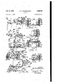
- Fig.1 is a plan .viewofa partiallyioldewblanle from which one" form" ortmodification'pf-the improved carton of thisinvention ma-y be-erecte'd- Fig; 2 is a perspective view of"a partially erected carton from theiblank-of *il ig: 1:
- Fig. 3 is a: transversesectional" view through the blank of the cartonasit leavesthe'forming machine for deliveryito: the .user:
- Fig; 4 is a transverse”. sectionah view through the side walls of the'cartonofFig:2asseen fromline 13-4 on saidiFig: 2;"
- Fig. 5 is a fragmentary horizontal sectional view through theside walls andadj'acentend wall' ofthe erected carton ofFig.'*2as' seen from line 5-5 on said Fig.2.
- Fig. 6 is. a fragmentaryv longitudinal sectional view through'the carton. and particularly one end thereof as seen from line 6''5JonFig:6;
- Fig. 7 is vertical sectional:view"'through-"an** end wall .of the erected carton of Fig? 2taken'*on* line. 'il on said" Fig. 2.
- Fig. 8 is a plan view ofa partially folded
- Fig. 9 .isa. transversev sectionallvi'ew through: an erected cartonformed from. the. blank of" Fig; 8..
- Fig. 10 is a; planview ofYaihalflpartl'y folded ⁇ . modified blank. again. embodying the improve.
- Fig. 13 is a'perspective' view ofa'partially erectedv carton. formed from the blankfofFig: 12.
- Fig. 14 is. a view similar to Fig, l3"showi'ng the carton in an erected stage. further'alongfthen" ,ti'onal 'view through the end ofoneof tliewalls of the carton of Fig. 15 as seen particularly from line
- Fig. 17 is a bottom plan view of one end of the erected carton of Figs. 13 and 14.
- Fig. 18 is a plan view of a partly folded half blank embodying the improvements of this invention and incorporating modifications over the blank of Fig. 12.
- Fig. 19 is a transverse, perspective sectional view of a carton erected from the blank of Fig. 18.
- Fig. 20 is a bottom plan view of one end of the erected carton of Fig. 19.
- this invention pertains to improvements in knock-down boxes or cartons of the hollow wall type.
- Each of the modifications to be hereinafter described contain one or more hollow walls which is reinforced or strengthened both transversely and vertically thereof.
- the foldable wall used therewith may be of contacting inner and outer wall members or spaced apart Wall members with the latter strengthened or reinforced vertically and horizontally or without such reinforcement as desired.
- Figs. 1 to '1, inclusive use is made of a blank cut or died and scored as illustrated in Fig. 1 with the blank comprising a bottom panel 25 bounded by score or fold lines 26, 21, 28 and 29.
- the score or fold lines 21 and 29 will be referred to' as the sides while the remaining score and fold lines 26 and 28 will be referred to as the ends, but it is to be understood that this terminology is used merely for purposes of convenience since the terms are interchangeable, the longer edges of a box being usually designated as the sides while the shorter is designated as the ends.
- the base 25 has hingedly connected therewith through the score or fold lines 21 and 29 similar extensions 38 and 3
- the base 25 has hingedly connected with its ends through the score or fold lines 26 and 28 similar extensions 32 and 33 which, again, in the erected carton form the. end walls thereof.
- is subdivided by a'plurality of score or fold lines 34, 35, 36, 31, 38, 39, 40 and 4
- inclusive are indicated by dash lines and this same system will be followed wherever score or fold lines are indicated while the solid lines will indicate cuts.
- the panel 42 forms the side wall outer wall member and has its ends defined by score or fold lines and 52.
- the panel 43 in the erected carton forms the side Wall top wall while the panel 44 forms the side wall inner wall member.
- the ends of the top wall panel 43 are defined by cut lines while the ends of the inner wall member 44 are defined by score or fold lines 53 and 54.
- the inner wall member panel 44 near its outermost corners, when extended as in Fig. 1 or near its lower innermost corners, when in the erected position, i provided with slits or narrow elongated apertures 55 and 56 which are utilized, as will later be made clear, to receive locking lugs from the carton end wall to hold the carton in erected positions.
- glue or adhesive may be applied to the under side of panels 46 and 50, as seen in Fig. 1, and to the upper side of panel 48 again as seen in Fig. 1, but preferably the outer wall member or panel 42 is provided with spaced ribbons of adhesive as indicated at 51 and 58 and the adhesive 59 is applied to the upper surface of the panel 48.
- each of the said adhesive ribbons is applied with the blank in the position illustrated in Fig. 1.
- the side wall vertical braces or glue flap panels 59, 48, and 46 each, respectively, have their ends defined by score or fold lines 68 and 6
- the side wall bottom wall member, and transverse brace panels 41 and 49 each have their ends cut and these cuts are in alignment with the score or fold lines for the various side wall panels as well as in line with the carton bottom or base end scores or fold lines 26 and 28.
- the side wall outer wall member 42 through its ends scores or fold lines 5
- flaps or flanges subdivided by score or fold lines which are extensions of the score of fold lines 35 to 4
- the flange or flap panels 18, 12, 14 and 16 are each spaced from its side wall extension panel by a rectangular opening while flap panels 1
- the width that is the dimension running in the direction lengthwise of the side wall, of the panels 82 to 85, inclusive, and of the openings 18 to 8
- extension 33 is provided with a plurality of score or fold lines 86, 81 and 88 subdividing the extension into panels 89, 90, 9
- the panel 89 constitutes the end wall outer wall member and has its ends defined by score or fold lines 93 which are in alignment with the base score or fold lines 21, and 29.
- the said score or fold lines 93 integrally hinged connect to the panel 89 the adja cent corner pieces 66 and 61.
- the panel 90 in the erected carton forms the end wall top wall ageee rea member while the panel 9! forms the" end wall inner "walr member? lengthequal thereto while the portion thereof adjacentithe panel 9
- the glue flap 50 along with the panel H 'atthe ends thereof are upwardly turned into: face contact with" the bracing panel" 59 whereupon theseipanels 'along with their end flanges panel. 16,. are then downwardly folded on the scoreor fold line iii-to bring the same-into face contact with the underside of the glue flap 48.
- the superimposed panels 59, 49 and 68 along with; panels 13-! and-46- arenow folded on the score or fold line'BT thereby bring glue panel iilinto engagement with the side wall inner wall member panel M for adhesively securingthe said glue panel' l8to the side wall inner wall member.
- the tucking flap assemblies which includes the extension end flanges or flap panels 19 to 11 in--- elusive are folded relative to one another'at' the' same time that the side wall panels are folded and the said extension flange or flap panel" 15 is provided with adhesive 98 and is secured to the panel. H at the time that the side wall glue panel iB'is secured to the side "wall" inner-wall” member 44. It is therefore evident that" upon the setting up of the carton side" walls. from their fiat folded positionsiof'Fig. 3 to their'erected positions in Fig; 2 automatically sets'upthe tucking flap assemblies to the positionsillus trated at the lower end of Fig. '2.
- the said tucking flap assemblies are provided with transverse braces which include the panels 16; 14, 12 andmr As seen in Fig. 6 the end wall inner and outer wall members 8% and 9! are transversely braced by the above identified composite tucking flap braces '58, 74, I2 and 10. These transverse braces resist movement,. or displacement of the end wall inner and outer wall members individually and as a unit.
- the blank has eliminated therefrom the glue panel 46 and transverse brace 41 and has the glue panel 48 integrally connected with the side wall bottom panel through the score'or fold line 31.
- the processing of the modified'blank'of Fig. 8' is identical with that above described in connection with 'Fig; 1 and the setting up of the blank follows the same steps.
- the resulting boxor carton has substantiallythe same extension appearance as results from the blank of Fig. 1, the only difference being that the-side walls and end walls each have their respective inner and outer wall members braced by a single transversebrace instead of two such braces.
- the resulting side and end walls are again of cellular construction but have onlytwo cellsinstead of three.
- transverse braces may be provided. It may be noted that the number of such transverse braces depends upon the height of the carton walls and the use to which it is to be put as well as the goods to be packed and shipped therein.
- the box or carton has been provided with four walls each of hollow or spaced apart construction. It is sometimes desirable that the box or carton merely have two walls of the hollow or spaced apart construction with the remaining wall of appreciably less thickness, such for example as a double thickness.
- Figs. 10 and 11 a modified blank to accomplish this result. Accordingly the blank of Fig. 10 has eliminated from its side wall extensions 38' and 3
- a further modification consists in eliminating from the side wall inner wall member panel 44 the slits or elongated apertures 5-5 and 58 substituting therefor a notch H03 in the outermost corner of said side Wall inner wall member M3.
- the blank of Fig. is further modified in the end wall extensions 32 and 33 which as illustrated in Fig. 10, in the end wall extension 32' consists essentially of eliminating the end wall top wall panel 90 retaining the end wall outer wall panel 89, end wall inner wall panel 9!, and spacer panel 92 with said end wall inner and outer wall member panel 85 and st separated from one another by the score or fold line 56 and said imier wall member panel 8! and spacer panel 92 separated from one another by a score or fold line 88.
- the side wall extensions 36' and 3! are illustrated as of the construction of modified blank of Fig. 8 but it is to be understood that they may be made as illustrated in Fig. 1 since the number of cells or transverse braces in the carton side walls may vary and still use the substantially thin or double material thickness end wall of Figs. 10 and 11.
- the blank of Fig. 10 is folded, insofar as side wall extensions are concerned in substantially the same manner as the blanks of Figs. 1 and 8 and is shipped to the user in the folded knocked-down condition.
- the user in setting up the blank of Fig. 10 again, follows the same procedure as was followed in setting up the cartons in Figs. 2 and 9.
- the setting up of the carton of Fig. 11 requires the positioning of the tucking flaps 99 as the bellow corner pieces 86 and t1 transverse of the carton base or bottom 25 prior to the folding of the end Wall panels onto one another.
- the flaps 92 are modified blank of Fig. 10, instead of being positioned between the inner and outer wall members 89 and 9!, are arranged on the carton base or bottom to project into the carton and is a form of creeper as heretofore employed in boxes or cartons.
- the boxes or cartons heretofore described pre sented the right or finished side of the paper or cardboard exteriorly of the side and end walls as Well as interiorly thereof, but presents to the user the wrong side of the paper or cardboard on the base or bottom.
- the carton or boxes illustrated in Figs. 12 to 20 inclusive are designated for this purpose and to have the Walls of reinforced or cellular construction.
- FIG. 12 One form of such carton is illustrated in Fig. 12 which, it will be observed, is quite similar to the blank of Fig. 8 since the resulting carton or box has but a single transverse brace.
- This blank in so far as the side wall extensions are concerned, is modified over the blank of Fig. 8 to the extent that the panels or side walls outer wall members and top wall members as and 44 are made longer than the adjacent base or bottom bounding score or fold lines 27 and 29.
- the said panels 43 and M are increased in length the amount of the width of the panels 82 which constitute the spacing of the end wall inner and outer wall members and is occasioned by the fact that the end walls of Fig. 12 are folded from the inside out While the corresponding end walls of Fig. 8 are folded from the outside in.
- the blank of Fig. 12 has the end wall extensions 32 and 33 modified over that in Fig. 8, one of which is illustrated in said Fig. 12 and indicated by the reference numeral 32", to the extent that the panel 355 is of less length than the panel EH since these panels respectively form the end wall inner and outer wall members instead of the end wall outer and inner wall members as do the panels in the said blank of Fig. 8.
- the panel 92' of the blank of Fig. 12 becomes the locking panel instead of a mere spacing panel as the corresponding panel 92 of Fig. 8 is employed.
- the setting up of the blank of Fig. 12 is in effect rever ed to that of the blank of Fig. 8 since the panel 55 or glue flap is secured to the inner surface of the inner Wall member in such a manner that the bottom wall panel 45 is outwardly of the bounding score or fold lines 27 and 29 as illustrated clearly in Fig. 15.
- the glued up blank is shipped to the user with both side wall extensions in the position of the side wall extension 38 of Fig. 12.
- the tucking assemblies are now arranged to V be transversely of the carton and to be placed in face contact with the folded corner pieces 66 and 67 again as illustrated in Fig. 14 in so far as one of said tucking flap assemblies is concerned.
- the end wal1 extension panels 9B, 9! and 92' are now folded to be normal to one another which disposes the panel or flap 52' against the lower surface or" the bottom or base 25.
- brace substantiallymidway of the height of the carton or this bracing may take the form of a ,plurality of transverse braces suitably spaced ,afrom one ,another vertically of .their. height.
- a cartonof the class described formedfrom la singleblank comprising a bottom,.extensions from two opposed sides ofsaidbottom" subdivided into panels to formlside walls upstanding from opposite edgesof said bottom, each sidewall including an innerandanouter wall imember spaced from one anothenan appreciabledistance with a top wall'memberjoining the 'upperends ofv said inner andouter wall'members, means for articulating the said inner, outer and top wall members of each sidewall to one .another and .to the bottom, each extension including panels to form beyond its inner. and 'outer wall members a1ternate glue 'flaps'and transverse braces with certain of said glue flaps connected to :the interior surface of its.
- each side wall'and'its' braces may be folded flat for erection by merely raising same from its fiat position to 'haveits inner and'outer'wall members' normaltothe bottom'andithe braces parallel withithe bottom, and .extensionsfrom the remaining sides of the bottom forming end walls to upstand therefrom, each of said .end walls including an inner .and "an .outer wall member spaced from one another an appreciable distance withv a top wall membergjoining the upper ends ofsaid end wall inner and .outer wall members, means carried .by.'the1side'w.alls to be enfolded .by the end walls inner and outer wall members for transversely bracing said end walls inner and
- each extension including .panels to formbeyon'd “its'inner and outer wallmem- "hers :alternate glue *flaps and transverse braces "with certain "of said glue flaps connected to the interior surface of its inner wall member and certain of said glue flaps connected to the inner I surface of its outer wall member with the transverse braces thereof extending between the said inner and outer Wall members and parallel with the bottom at points intermediate the carton bottom and side wall top wall member, so that each side wall and its braces may be folded flat for erection by merely raising same from its fiat position to have its inner and outer wall members normal to the bottom and the braces parellel with the bottom, and extensions from the re- 'maining sides of the bottom forming end walls to upstand therefrom, each of said end walls including an inner and an outer wall member spaced from one another an appreciable distance with a top wall member joining the upper ends of said end wall inner and outer wall members,
- a single blank comprising a bottom, extensions from two opposed sides of said bottom subdivided into panels to form side walls upstanding from opposite edges of said bottom, each side wall including an inner and an outer wall member spaced from one another an appreciable distance with a top wall member joining the upper ends of said inner and outer wall members, means for articulating the said inner, outer and top wall members of each side wall to one another and to the bottom, each extension including panels to form beyond its'inner and outer wall members alternate glue flaps and transverse braces with certain of said glue flaps connected to the interior surface of its inner wall member and certain of said glue flaps connected to the inner surface of its outer wall member with the transverse braces thereof extending between the said inner and outer wall members and parallel with the bottom at points intermediate the carton bottom and side wall top wall member, so
- each side wall and its braces may be folded fiat for erection by merely raising same from its fiat position to have its inner and outer wall members normal to the bottom and the braces parallel with the bottom, and extensions from the remaining sides of the bottom forming end walls to upstand therefrom, each of said end walls including an inner and an outer wall member spaced from one another an appreciable distance with a top wall member joining the upper ends of said end wall inner and outer wall members, tucking flaps assemblies from the ends of the side walls comprising articulated vertical and v horizontal members adapted to be enfolded by the end walls inner and outer wall members for vertically and horizontally bracing the same, and means for locking the side and end walls in upstanding positions.
- a carton of the class described formed of a single blank of card or paper board comprising a carton bottom, extensions from two opposed sides of said carton bottom each subdivided to provide ,panels erectable into side walls each formed of an inner and an outer wall member spaced from one another an appreciable distance, with one of said inner and outer wall members articulated to the carton bottom a top wall member joining the upper ends of said inner and outer wall members and a bottom wall member carried by the other of said inner and outer wall members, said extensions including panels from said bottom wall members providing glue flaps and transverse braces with certain of said glue flaps connected to the interior surface of its carton bottom articulated side wall member and certain of said glue flaps connected to the opposed inner surface of the remaining side wall member with the transverse braces extending between the said side walls inner and outer wall members and parallel with the bottom, whereby said spaced inner and outer wall members are transversely braced, end walls from the remaining edges of the bottom, and means for locking the side and end walls in upstanding operative positions.
- a carton of the class described formed of a single blank of card or paper board comprising a carton bottom, extensions from two opposed sides of said carton bottom subdivided to provide panels erectable into side walls each formed of an inner and an outer wall member spaced from one another an appreciable distance, with one of said inner and outer wall members articulated to the carton bottom, a top wall member joining the upper ends of said.
- said extensions including panels from said bottom wall members providing glue flaps and transverse braces with certain of said glue flaps connected'to the interior surface of its carton bottom articulated side wall member and certain of said glue flaps connected to the opposed inner surface of the remaining side wall member with the transverse braces extending between the said side walls inner and outer wall members and parallel with the bottom, whereby said spaced inner and outer wall members are transversely braced, end walls from the remaining edges of the bottom, means for locking the side and end walls in upstanding operative positions, said end walls each formed of an extension from the ends of the bottom panel and comprising panels to form end wall inner and outer wall members, and tucking flaps at the ends of the side walls to be enfolded by the end walls inner and outer wall members.
- a carton of the class described formed of a single blank of card or paper board comprising a carton bottom, extensions from two opposed sides of said carton bottom each subdivided to provide panels erectable into side walls each formed of an inner and an outer wall member spaced from one another an appreciable distance, with one of said inner and outer wall members articulated to the carton bottom, a top wall member joining the upper ends of said inner and outer wall members, a bottom wall member carried by the other of said inner and outer wall members, and panels from said bottom Wall members providing glue flaps and transverse braces with certain of said glue flaps connected to the interior surface of its carton bottom articulated side wall member and certain of said glue flaps connected to the opposed inner surface of the remaining side wall member with the transverse braces extending between the said side walls inner and outer wall members and parallel with the bottom, whereby said spaced inner and outer wall members are transversely'braced, end walls from the remaining pre ame 13 edges of, the bottom, means for locking the side and end walls in upstanding operative positions, said end walls being formed from
- a carton of the class described formed of a vsingle'blank of card or paper board comprising a carton bottom, extensions from two opposed .sides .of said carton bottom each subdivided to provide panels erectable into sidewalls each formed of an inner and outer wall member spaced from one another an appreciable distance, with one of said inner and outer wall members articu- 'lated to the carton bottom a top wall member [joining the upper ends of said inner and outer wall members, a bottom wall member carried "by the other of said inner and outer wall members, and panels from said bottom wall members providing glue flaps and transverse braces with certain of said glue 'fiaps'connected to the ing operative positions, each of said end walls formed from .an extensionfrom an opposite end of the bottom with each extension :subdivided ,,into .panels for providing ,each end wall with .aninner andan outer wall member spaced from one another an appreciable distance joined by .a top wall member,
- a carton of the class described formedfrom 'a single blank comprising a carton bottom, ex- ":tensions'from two opposedsides of the-carton bottom subdivided by score or fold lines to form side 'walls each of an inner and an outer wall member.
- a carton of theclass described formed from a single blank comprising "a carton bottom, extensions from two opposed sides of the carton bottom subdivided by score or fold lines to form side walls each of an inner and an outer wall member spacedfrom one 'anotheran appreciable distance with a top wall member between them and with one of said innerand outer wall members hingedly connected to the carton bottom, at least one of said extensions beyond'its inner and outer wall members having'panels disposed within the inner-and outer wall members of'its side wall and secured thereto to dispose oneof said panels parallel'with the carton bottom and spaced therefrom to form in said side wall, "at least, one transverse'brace extending between op- ;posed inner faces of said side wall inner and outer wall members, said sidewalls inner and outer wall members and transverse bracesecuring and forming panels, respectively, through their score lines being'articulated'to one'another whereby they may be foldedto a hat position for shipping purposes and to an upstanding position for carton erection, end walls from "the” remaining
- a carton of the class described formed of a single blank of card or paper board comprising a carton bottom, extensions from two opposed sides of said carton bottom each subdivided to provide panels erectable into side walls each formed of an inner and an outer wall member spaced from one another an appreciable distance, with one of said inner and outer wall members articulated to the carton bottom, a top wall member joining the upper ends of said inner and outer wall members, a bottom wall member carried by the other of said inner and outer wall members, and panels from said bottom wall members providing alternate glue flaps and transverse braces with certain of said glue flaps connected to the interior surface of its carton bottom articulated side wall member and certain of said glue flaps connected to the opposed inner surface of the remaining side wall member with the transverse braces extending between the said side walls inner and outer wall members and parallel with the bottom, whereby said spaced inner and outer wall members are transversely braced, end walls from the remaining edges of the bottom, said side walls bottom wall members being positioned exteriorly of the sides of the bottom to which the side walls upstand, said
- a carton of the class described formed of a single blank of card or paper board comprising a bottom, extensions from two opposed sides of said carton bottom each subdivided to provide panels erectable into side Walls each formed of an inner and an outer wall member spaced from one another an appreciable distance, with one of said inner and outer wall members articulated to the carton bottom, a top wall member joining the upper ends of said inner and outer wall members, a bottom wall member carried by the other of said inner and outer wall members, and panels from said bottom wall members providing glue flaps and transverse braces with certain of said glue flaps connected to the interior surface of its carton bottom articulated side wall member and certain of said glue flaps connected to the opposed inner surface of the remaining side wall member with the transverse braces extending between the said side walls inner and outer wall members and parallel with the bottom, whereby said spaced inner and outer wall members are transversely braced, end walls from the remaining edges of the bottom, said side walls bottom wall members being located exteriorly of the carton bottom edges to which the side walls are articulated with the opposite ends
- a carton of the class described formed of a single blank of card or paper board comprising a bottom, extensions from two opposed sides of said carton bottom each subdivided to provide panels erectable into side walls each formed of an inner and an outer wall member spaced from one another an appreciable distance, with one of said inner and outer wall members articulated to the carton bottom, a top wall member joining the upper ends of said inner and outer wall members, a bottom wall member carried by the other of said inner and outer wall members, and panels from said bottom wall members providing glue flaps and transverse braces with certain of said glue flaps connected to the interior surface of its carton bottom articulated side wall members and certain of said glue flaps connected to the opposed inner surface of the remaining side wall member with the transverse braces extending between the said side walls inner and outer wall members and parallel with the bottom, whereby said spaced inner and outer wall members are transversely braced, end walls from the remaining edges of the bottom, said side walls bottom wall members being located exteriorly of the carton bottom edges to which the side walls are articulated with the opposite ends of
Description
Feb. 17, 1953 W.P. FRANKENSTEIN 2,628,763
CARTON Filed Jan. 3, 1947 4 Sheets-Sheet l IN V EN TOR.
Y WM PFnn/vknvs TEIN Feb. 17, 1953 w. P. FRANKENSTEIN I 2,628,763
CARTON Filed Jan. .5, 1947 4 Sheets-Sheet 3 H55 as INVENTOR.
04 5 96 25 96 Wu. F. Fan/drums rs/1v ATT RNE Feb. 17, 1953 w. P. FRANKENSTEIN 2,628,7 3
CARTON Filed Jan. 3, 1947 4 Sheets-Sheet 4 Patented Feb. 17, 1953 UNITED STATES OFFICE CARTON William Frankenstein; CincinnatLQOhiox Application January 3, 1947, SerialNo. 720,125"
This". invention relates to improvements in. cartons or boxes and particularly tosuch boxes as are-known as knock-down'boxes.
This application pertains to improvements in.
hollowwallboxes such asdisclosed in applicants Patent: Re. 21,158 as well as to improvements in the disclosure in pending application to Freel and .JonesiSerial No. 375,306, now Patent No. 2,447,243.
overcomes. ltqis therefore the principal object of the present, invention to. provide: a box or carton of theihollow: wall typerin which the wall: members.
thereof are reinforced or: strengthened;
Another object of thepresent invention is the provision of a carton orboxthat will accomplish. the:.foregoing. object without sacrificing the advantages of ahollow wall knock-down box or" carton-:inqso 'farasiease: of set up: is concerned andwhich..isiinherent. in thestructure'of the. patent and: applicationabove .identified.
Az/furtherobject ofithei present invention is theiprovision of a-boxyor. carton of the. hollow or.
spacedzapart'wa'll type iniwhich there is provided one or more transverse: ribs or braces thereby strengthening thesaidwall' and specifically preventing: inwardbulgingof either the inner or outer. wall members:
A still further vobjectrof the: present" invention, is the provision ofxa box oricarton. having one or more hollow or-spaced apartwallsand whichlwall.
is materially strengthened both transversely and.
vertically thereof.
A. still further; andimportant object of the present. invention-sis. theprovision of a box. or..'
carton that will accomplish the objects set forth above andwhich. is formed of a single'blank and shipped to thexuser in aknocked-downcondition requiringthe .user to. merely raise-"the walls and loclrthem'in. raised positions.
Asstill further and specific object of the.inven-- tionv. is. the provision of a foldable' hollow or spaced, apartwall' with which isused tucking assemblies that are transversely and/or vertically reinforced to therebyreinforce the foldable wall and prevent the bulging either inwardly or outwardlyof the spaced apartmembers of said foldable wall.
Other objects andadvantages oi. the;present invention should: be readily apparent byreference. to. the following specification. considered in Each; of: these prior constructions utilizes a hollow wall of spaced-apart innerand outer Wall memberswhich when .madein rela--' tively large sizes-exhibited Weaknesses therein l and which: weaknesses the. present: invention spirit" of the invention;
In the drawingsr Fig.1 is a plan .viewofa partiallyioldewblanle from which one" form" ortmodification'pf-the improved carton of thisinvention ma-y be-erecte'd- Fig; 2 is a perspective view of"a partially erected carton from theiblank-of *il ig: 1:
Fig. 3 is a: transversesectional" view through the blank of the cartonasit leavesthe'forming machine for deliveryito: the .user:
Fig; 4 is a transverse". sectionah view through the side walls of the'cartonofFig:2asseen fromline 13-4 on saidiFig: 2;"
Fig. 5 is a fragmentary horizontal sectional view through theside walls andadj'acentend wall' ofthe erected carton ofFig".'*2as' seen from line 5-5 on said Fig.2.
Fig. 6 is. a fragmentaryv longitudinal sectional view through'the carton. and particularly one end thereof as seen from line 6''5JonFig:6;
Fig. 7 is vertical sectional:view"'through-"an** end wall .of the erected carton of Fig? 2taken'*on* line. 'il on said" Fig. 2.
Fig. 8 is a plan view ofa partially folded;
slightly modified half blankfor erecting'awarton' of the. present invention.
Fig. 9 .isa. transversev sectionallvi'ew through: an erected cartonformed from. the. blank of" Fig; 8..
Fig. 10 is a; planview ofYaihalflpartl'y folded}. modified blank. again. embodying the improve.
ments. of this. invention. combined. with ,a: modi-=- Fig.- 11. is..a. transverse:- sectional. view1;of:. .a-n.-' erected carton formed from. the zblankiof Fig; 10; Fig. 12 is a plan viewof apartly io'lded blanler erected to a-modifiedcarton= embodying the improvements of this'in-vention- Fig. 13 is a'perspective' view ofa'partially erectedv carton. formed from the blankfofFig: 12. Fig. 14 is. a view similar to Fig, l3"showi'ng the carton in an erected stage. further'alongfthen" ,ti'onal 'view through the end ofoneof tliewalls of the carton of Fig. 15 as seen particularly from line |6-|6 on said Fig. 15.
Fig. 17 is a bottom plan view of one end of the erected carton of Figs. 13 and 14.
Fig. 18 is a plan view of a partly folded half blank embodying the improvements of this invention and incorporating modifications over the blank of Fig. 12.
Fig. 19 is a transverse, perspective sectional view of a carton erected from the blank of Fig. 18.
Fig. 20 is a bottom plan view of one end of the erected carton of Fig. 19.
Throughout the several views of the drawings similar reference characters are employed to denote the same or similar parts.
As was noted above this invention pertains to improvements in knock-down boxes or cartons of the hollow wall type. Each of the modifications to be hereinafter described contain one or more hollow walls which is reinforced or strengthened both transversely and vertically thereof. As will later be apparent, with this basic thought, the foldable wall used therewith may be of contacting inner and outer wall members or spaced apart Wall members with the latter strengthened or reinforced vertically and horizontally or without such reinforcement as desired.
Specifically and referring to Figs. 1 to '1, inclusive, use is made of a blank cut or died and scored as illustrated in Fig. 1 with the blank comprising a bottom panel 25 bounded by score or fold lines 26, 21, 28 and 29. In the description hereinafter the score or fold lines 21 and 29 will be referred to' as the sides while the remaining score and fold lines 26 and 28 will be referred to as the ends, but it is to be understood that this terminology is used merely for purposes of convenience since the terms are interchangeable, the longer edges of a box being usually designated as the sides while the shorter is designated as the ends.
The base 25 has hingedly connected therewith through the score or fold lines 21 and 29 similar extensions 38 and 3| which in the erected carton form the side walls thereof. The base 25 has hingedly connected with its ends through the score or fold lines 26 and 28 similar extensions 32 and 33 which, again, in the erected carton form the. end walls thereof.
The side walls extensions 30 and 3| are substantially identical with one another wherefore it is deemed sufficient if but one of them, 3| for example, be described in detail to suifice for the both.. Accordingly, extension 3| is subdivided by a'plurality of score or fold lines 34, 35, 36, 31, 38, 39, 40 and 4| into panels 42, 43, 44, 45, 46, 41, 48, 49 and 50. It should be noted that the score or fold lines 34 to 4| inclusive are indicated by dash lines and this same system will be followed wherever score or fold lines are indicated while the solid lines will indicate cuts.
.In the erected carton the panel 42 forms the side wall outer wall member and has its ends defined by score or fold lines and 52. The panel 43 in the erected carton forms the side Wall top wall while the panel 44 forms the side wall inner wall member. The ends of the top wall panel 43 are defined by cut lines while the ends of the inner wall member 44 are defined by score or fold lines 53 and 54. The inner wall member panel 44 near its outermost corners, when extended as in Fig. 1 or near its lower innermost corners, when in the erected position, i provided with slits or narrow elongated apertures 55 and 56 which are utilized, as will later be made clear, to receive locking lugs from the carton end wall to hold the carton in erected positions. The remaining panels 45 to 56, inclusive, form in the erected carton the side wall bottom panel, side wall transverse braces, and glue flaps or side wall vertical braces. In practice glue or adhesive may be applied to the under side of panels 46 and 50, as seen in Fig. 1, and to the upper side of panel 48 again as seen in Fig. 1, but preferably the outer wall member or panel 42 is provided with spaced ribbons of adhesive as indicated at 51 and 58 and the adhesive 59 is applied to the upper surface of the panel 48. By applying the adhesive as just described each of the said adhesive ribbons is applied with the blank in the position illustrated in Fig. 1. The side wall vertical braces or glue flap panels 59, 48, and 46 each, respectively, have their ends defined by score or fold lines 68 and 6| forthe panel 50, 62 and 63, for the panel 48, and 64 and 65 for the panel 46. The side wall bottom wall member, and transverse brace panels 41 and 49 each have their ends cut and these cuts are in alignment with the score or fold lines for the various side wall panels as well as in line with the carton bottom or base end scores or fold lines 26 and 28.
The side wall outer wall member 42 through its ends scores or fold lines 5| and 52 has integrally hingedly connected therewith corner pieces 66 and 61 each of which corner pieces is respectively divided by a diagonal score or fold line 68 and 69. These corner pieces 66 and 61 form in the erected carton, a bellows corner.
Beyond the ends of the side wall panels transverse braces and glue flaps or panels are flaps or flanges subdivided by score or fold lines which are extensions of the score of fold lines 35 to 4|, inclusive, thereby providing in each flap or flange panels 18, 1|, 12, 13, 14, 15, 16 and 11 which are, in effect, extensions of panels 43 to 58, respectively. The flange or flap panels 18, 12, 14 and 16 are each spaced from its side wall extension panel by a rectangular opening while flap panels 1|, 13, 15 and 11 are each separated from its corresponding side wall extension panel by panels 82, 83, 84 and 85 whose outermost sides are defined by score or fold lines in alignment with the outermost edge of the openings 18 to 8|, inclusive. It should be noted that the width, that is the dimension running in the direction lengthwise of the side wall, of the panels 82 to 85, inclusive, and of the openings 18 to 8|, inclusive, is equal to the width of the end wall top wall member, as will later be made clear, and it should further be noted that the panels 82 to 85, inclusive, form hinges whereby the flap panels, after erection, may be swung to lie transversely of the base 25 and act as braces for the end walls.
The end wall extensions 32 and 33 are substantially duplicates of one another and it is deemed suificient if but one of them be described in detail for the both. Accordingly, extension 33 is provided with a plurality of score or fold lines 86, 81 and 88 subdividing the extension into panels 89, 90, 9| and 92 between the score or fold line 28 and the end of the extension.
In the erected carton the panel 89 constitutes the end wall outer wall member and has its ends defined by score or fold lines 93 which are in alignment with the base score or fold lines 21, and 29. The said score or fold lines 93 integrally hinged connect to the panel 89 the adja cent corner pieces 66 and 61. The panel 90, in the erected carton forms the end wall top wall ageee rea member while the panel 9! forms the" end wall inner "walr member? lengthequal thereto while the portion thereof adjacentithe panel 9| is of a length equal to said shorter panelwherefore the endsof the top'wall'panelfifl; beyond the-inner wall member Propanel st, is-contouredas at 94 and G5. jecting, from the 'sides of the panel 91, adjacent the outer ends thereof 'whenextending as in Fig: 1, andthe-inner loweren'ds-whenerected as in' Fig. 2; are: locking; lugs 96 and 91 which,
as intimated; entertheisi-de wall inner wall member slits 55* and56forlockingthe walls in erected position. In the erected carton the panel 92 acts-"as'aspacer for spacing the lower. end of the end wallinner-and outerwall member panels 89 and" fif'from "one another.
Afterthe blank has" been cut and scored as above'described the glue flap 50 along with the panel H 'atthe ends thereof are upwardly turned into: face contact with" the bracing panel" 59 whereupon theseipanels 'along with their end flanges panel. 16,. are then downwardly folded on the scoreor fold line iii-to bring the same-into face contact with the underside of the glue flap 48. The superimposed panels 59, 49 and 68 along with; panels 13-! and-46- arenow folded on the score or fold line'BT thereby bring glue panel iilinto engagement with the side wall inner wall member panel M for adhesively securingthe said glue panel' l8to the side wall inner wall member. The superimposed panels are now folded onthe score or fold line'35 thereby bringing' the glue flap 5!) and glue panel 46- into contact with'the'adhesive ribbons 51 and-58 for securing them to the inner face of side wall outer wall member panel. At this-time each of the sidewall. extensions 30 and 3| are; in" the folded and secured" position of the'extension 30 illustratedatthe top of. Fig: 1'. It. is-in this positionxthat the knock-down carton of the present invention is. shipped to the user. The folded andtglued .p'ositionsofthepartsare as illus-= tratediin cross section in.Fig: 3.
The user upondesiring: to; place merchandise tive position to' complete the carton and to look all ofthe walls "in their-operative relation to'o'nefanothen. Thesettingup'of the end walls is believed obvious, since; afterthe corner: pieces GB'jand'GT have been folded on'their diagonal scores or'fold lines 68 and'69, all that is required is that the various panels 89, 9B, 9! and 92 are to be folded to benormal to one another atwhich timethey willbelinthe positions illustrated in Fig. 6.
The raising'ofthe side walls from their flat positions: in Fig. 3 to their upstanding positions. in Fig; 2 aut'omaticallyarranged the top wall member. 1'3" and. bottom wall"member it'to be' parallel -to one *anotherandto the bottomwn 7a It will be noted that the-- end wallouter wall member panel 89 of a The connecting "top wall panel 90 hasthe'portion thereof adjacentthe panel 89 of a base 25. At the-same time the atransverse braces; 41 and 49 a where automatically" swungs. to; be; parallel with the top and bottom wall members:
and the bottom or'base 25 as seen clearly in: Fig. 4'. glue flap 50 are permanently secured to. the side walls inner and outer" wall members the transverse braces are retained: in their operative? positions. verse braces will resist any bending or 'displacement of either the inner or outer side wallmem bers' in either a direction toward the interior of the box or a direction outwardly thereof and at the same-time these transverse braces strength--- en the composite'wallsagainst bulging or other displacement. Since the side' transverse braces extend the full length of the said walls the same arebraced from end to end as clearlyillustrated in Fig; 7.
The tucking flap assemblies which includes the extension end flanges or flap panels 19 to 11 in--- elusive are folded relative to one another'at' the' same time that the side wall panels are folded and the said extension flange or flap panel" 15 is provided with adhesive 98 and is secured to the panel. H at the time that the side wall glue panel iB'is secured to the side "wall" inner-wall" member 44. It is therefore evident that" upon the setting up of the carton side" walls. from their fiat folded positionsiof'Fig. 3 to their'erected positions in Fig; 2 automatically sets'upthe tucking flap assemblies to the positionsillus trated at the lower end of Fig. '2. It will further be appreciated that the said tucking flap assemblies are provided with transverse braces which include the panels 16; 14, 12 andmr As seen in Fig. 6 the end wall inner and outer wall members 8% and 9! are transversely braced by the above identified composite tucking flap braces '58, 74, I2 and 10. These transverse braces resist movement,. or displacement of the end wall inner and outer wall members individually and as a unit.
Each of the side and end walls is. verti= cally. reinforced by the glue flaps and panels 59," 43 and 36 as well as the extension flange or'fiap panels thereof which are, respectively, 77, 15;.
and I3. I
By reference to Figs. 2, 4,.6,'.and 7' it will'be noted that. the .side and end wallsv are provided with cells between thetransverse braces and that.
with the blank of Fig. 1 there are three such cells; It may be desirable to increase or decrease the. number of cells and thereby the number of trans verse braces. Such a construction is illustrated in Figs; 8 and'9.
As illustrated in Fi 8 the blank has eliminated therefrom the glue panel 46 and transverse brace 41 and has the glue panel 48 integrally connected with the side wall bottom panel through the score'or fold line 31.
The processing of the modified'blank'of Fig." 8' is identical with that above described in connection with 'Fig; 1 and the setting up of the blank follows the same steps. The resulting boxor carton has substantiallythe same extension appearance as results from the blank of Fig. 1, the only difference being that the-side walls and end walls each have their respective inner and outer wall members braced by a single transversebrace instead of two such braces. The resulting side and end walls are again of cellular construction but have onlytwo cellsinstead of three. It will be readily apparent that by adding panels instead ofsubtractin'g panels from-'-t11e"-side"wai1"exten Since the glue panels 46 and48 and It will beobvious that the's-aidtrans-- 7 sions 3i and 32 a greater number of transverse braces may be provided. It may be noted that the number of such transverse braces depends upon the height of the carton walls and the use to which it is to be put as well as the goods to be packed and shipped therein.
In each of the foregoing modifications the box or carton has been provided with four walls each of hollow or spaced apart construction. It is sometimes desirable that the box or carton merely have two walls of the hollow or spaced apart construction with the remaining wall of appreciably less thickness, such for example as a double thickness. There is illustrated in Figs. 10 and 11 a modified blank to accomplish this result. Accordingly the blank of Fig. 10 has eliminated from its side wall extensions 38' and 3| the end flanges with the exception that the side wall outer wall member has integrally hingedly connected therewith through the score or folded line 53 a tucking flap 99. A further modification consists in eliminating from the side wall inner wall member panel 44 the slits or elongated apertures 5-5 and 58 substituting therefor a notch H03 in the outermost corner of said side Wall inner wall member M3.
The blank of Fig. is further modified in the end wall extensions 32 and 33 which as illustrated in Fig. 10, in the end wall extension 32' consists essentially of eliminating the end wall top wall panel 90 retaining the end wall outer wall panel 89, end wall inner wall panel 9!, and spacer panel 92 with said end wall inner and outer wall member panel 85 and st separated from one another by the score or fold line 56 and said imier wall member panel 8! and spacer panel 92 separated from one another by a score or fold line 88.
The side wall extensions 36' and 3! are illustrated as of the construction of modified blank of Fig. 8 but it is to be understood that they may be made as illustrated in Fig. 1 since the number of cells or transverse braces in the carton side walls may vary and still use the substantially thin or double material thickness end wall of Figs. 10 and 11.
The blank of Fig. 10 is folded, insofar as side wall extensions are concerned in substantially the same manner as the blanks of Figs. 1 and 8 and is shipped to the user in the folded knocked-down condition. The user in setting up the blank of Fig. 10, again, follows the same procedure as was followed in setting up the cartons in Figs. 2 and 9. The setting up of the carton of Fig. 11 requires the positioning of the tucking flaps 99 as the bellow corner pieces 86 and t1 transverse of the carton base or bottom 25 prior to the folding of the end Wall panels onto one another. The flaps 92 are modified blank of Fig. 10, instead of being positioned between the inner and outer wall members 89 and 9!, are arranged on the carton base or bottom to project into the carton and is a form of creeper as heretofore employed in boxes or cartons.
The boxes or cartons heretofore described pre sented the right or finished side of the paper or cardboard exteriorly of the side and end walls as Well as interiorly thereof, but presents to the user the wrong side of the paper or cardboard on the base or bottom. In some instances, such for example when it is desired to print on the sides and inner face of the base or bottom, it is desirable and necessary that the same or right side of the paper or cardboard to be presented to the observer on the inner and outer surfaces of the side and end walls as wellas on the upper g surface of the base or bottom. The carton or boxes illustrated in Figs. 12 to 20 inclusive are designated for this purpose and to have the Walls of reinforced or cellular construction.
One form of such carton is illustrated in Fig. 12 which, it will be observed, is quite similar to the blank of Fig. 8 since the resulting carton or box has but a single transverse brace. This blank, in so far as the side wall extensions are concerned, is modified over the blank of Fig. 8 to the extent that the panels or side walls outer wall members and top wall members as and 44 are made longer than the adjacent base or bottom bounding score or fold lines 27 and 29. The said panels 43 and M are increased in length the amount of the width of the panels 82 which constitute the spacing of the end wall inner and outer wall members and is occasioned by the fact that the end walls of Fig. 12 are folded from the inside out While the corresponding end walls of Fig. 8 are folded from the outside in.
The blank of Fig. 12 has the end wall extensions 32 and 33 modified over that in Fig. 8, one of which is illustrated in said Fig. 12 and indicated by the reference numeral 32", to the extent that the panel 355 is of less length than the panel EH since these panels respectively form the end wall inner and outer wall members instead of the end wall outer and inner wall members as do the panels in the said blank of Fig. 8. The panel 92' of the blank of Fig. 12 becomes the locking panel instead of a mere spacing panel as the corresponding panel 92 of Fig. 8 is employed.
The setting up of the blank of Fig. 12 is in effect rever ed to that of the blank of Fig. 8 since the panel 55 or glue flap is secured to the inner surface of the inner Wall member in such a manner that the bottom wall panel 45 is outwardly of the bounding score or fold lines 27 and 29 as illustrated clearly in Fig. 15. The glued up blank is shipped to the user with both side wall extensions in the position of the side wall extension 38 of Fig. 12.
The user upon desiring to set up the carton raised the said side walls to be normal to the base or bottom 25 whereupon the end wall extensions and tucking flap assemblies are in the positions of the near end of the particularly erected carton of Fig. 13. At this time the end walls are erected, in succession, by raising the end wall extension to be normal to the bottom 25 which disposes the end wall inner wall member or panel 39' in the position illustrated in Fig. 14 with the corner pieces 55 and 61 folded on themselves on their diagonal fold lines 69 and disposed transversely of the carton against the end wall inner wall member or panel 89'. This is illustrated in Fig. 14 in so far as one of the end wall corners is concerned.
The tucking assemblies are now arranged to V be transversely of the carton and to be placed in face contact with the folded corner pieces 66 and 67 again as illustrated in Fig. 14 in so far as one of said tucking flap assemblies is concerned. The end wal1 extension panels 9B, 9! and 92' are now folded to be normal to one another which disposes the panel or flap 52' against the lower surface or" the bottom or base 25.
In order to lock the walls in their erected positions the ends of the bottom wall panel at are left open for which purpose the score or fold line 371 at its extreme ends is changed to a cut or slit M32. This construction forms the ends of the side wall bottom wall into tabs or lugs beneath which the said panel or flap 92 has its corners inserted, as illustratedin Fig. 17, the said ends pr .,the..,side -wa1l bottom wall members, which eactnas .ilocking' tabs, .orllugsindicated by theref- ..erence numeral"! 03.
.The: foregoing description provided a carton or lboxlin which each of theside'walls as well as'the send walls. are of the spaced apartconstruction with a transverse "brace between said walls and .,'located intermediate the upper and lower ends ethereof. llnorder toprovidea cartonwith spaced 1apartorihollow sidewalls but merely double thick- ;ness-end walls ablanksuch as illustrated'in Fig. 18, may be. employed. This blank is'provided' with end wall. extensions, such asillustrated in Fig. 10, modified to the extent that thepanel 89" is less ,lengthfthan the panel 9 I since the panelfill" in Fig. ,18'forms the end wall inner wall member while the corresponding panelin'Fig. 10 forms the ,endwallouter wall member with the panels 9| and '9l" again reversing their positions in the ,erectedicarton. The panel 92" in Fig. 18, is
viutilizedlas a .1ockingiflap in thesame manner. as itheflapiSZ. of.liiig.,l2,linstead of, utilizing this flap ',as:a.:creepersuch as described above in connection withfFigs, 10 and 11.
,The. erected carton from' the blank of Fig. "18 :=is.asLillustratedinSEig. 19 withlthe side walls bot- '.tom wall meniber'beyon'd the edges-of the carton lbaseiorbottom. "The ends of the said side wall ,bottom walLmembers areprovided with cuts or .slits .l 02,,..as was 'thelblank of Fig. 12 to receive x-Itherinjthe.norners=of the .lOckingfflap $25. 'The ,set upandlockingpf the .walls of the blanket Fig. 18 is asiillustrated in Fig.'20 whereinithe ends of the ,side wallsbottom wall membersiare in- :;di=cated aslocking tabs or.-fiaps N33 for the recepheights. It will-further benoted that the transverse'brace .may either be -a single transverse,
:brace substantiallymidway of the height of the carton or this bracing may take the form of a ,plurality of transverse braces suitably spaced ,afrom one ,another vertically of .their. height.
Each .of .the modifications of this invention ,accomplishesthe objects initially set forthand rovercomesia weakness ,in the boxes .or cartons lof thegeneral type herein described. and. illustrated and particularly when said boxes or cartons are \made to. have walls .ofv a relatively ,great height.
What is claimed is:
1-1. ,A carton ofthe-class described formed from (alsingle blankcomprising. a bottom, extensions :trom-twoopposed sides of said bottom subdivided ,into panelsto form side walls upstandingfrom opposite edges ofssaidlbottom, eachrside wall in- -=cludingan innerand an outer wall member ospaced from one another an appreciable .dis-
tancewith a top :walLmember joining the upper -iendsofisaid inner andouterwall. members, means for,-.;-.articulating ithe said inner, outerand :top
awallsmembersmof each side wall ltorone :another sand;to.thelbottom,;each. extension including-pan- ,elstdformbeyond 'itsinneran'douter wall mem- Zhersialtemate,-,g1ue "flaps and transverseibraces with certain of said glue flaps connected to the interior' surface of its inner wall member and "certain of said glue fiaps connected to the inner surface of its outer wall memberwith the transverse braces thereof extending"between thesaid inner and outer wall members and'parallel with the bottom at points intermediate the carton bottom and sidewall top wall membensothat each side wall and its'braces 'may be "folded fiat for'erection "by merely raising same'from its 'fiat position tohave its inner andout'er wall members .normal to "the bottom and the "braces par- .allel with the bottom, and extensions from the remainingsides of the bottomforming end walls to upstan'd therefrom, means for locking the side and end walls in said upstanding positions, said end walls each including "an inner and-an outer wall'member ,"joined at their upper ends, (and means'carried by thexside wallsto be en- 'folded .by the end walls inner and outer wall .members.
2. A cartonof the class described formedfrom la singleblank comprising a bottom,.extensions from two opposed sides ofsaidbottom" subdivided into panels to formlside walls upstanding from opposite edgesof said bottom, each sidewall including an innerandanouter wall imember spaced from one anothenan appreciabledistance with a top wall'memberjoining the 'upperends ofv said inner andouter wall'members, means for articulating the said inner, outer and top wall members of each sidewall to one .another and .to the bottom, each extension including panels to form beyond its inner. and 'outer wall members a1ternate glue 'flaps'and transverse braces with certain of said glue flaps connected to :the interior surface of its. inner wall member and certain of saidglue fiapsconnected to the inner surfaceiof its outer wall member Withithe transverse braces thereof extending betweenthe said inner and outer wall members and. parallel with the bottom at points intermediate the carton bo'ttomand side "walltop wall member, so that each side wall'and'its' braces may be folded flat for erection by merely raising same from its fiat position to 'haveits inner and'outer'wall members' normaltothe bottom'andithe braces parallel withithe bottom, and .extensionsfrom the remaining sides of the bottom forming end walls to upstand therefrom, each of said .end walls including an inner .and "an .outer wall member spaced from one another an appreciable distance withv a top wall membergjoining the upper ends ofsaid end wall inner and .outer wall members, means carried .by.'the1side'w.alls to be enfolded .by the end walls inner and outer wall members for transversely bracing said end walls inner and .outer wall members -at,,,points intermediate the height thereof,- and, means for locking the side and end walls in upstanding positions.
v3. ..A carton of the class.describedformedifrom asingleblankcomprising a bottom, extensions from two opposed sides of said bottom subdivided .into panels toiformside walls upstanding from opposite-edges of said bottom, each side wall I in- -cluding an inner and ,anouter wall member spaced from one anothenamappreciable; distance withla top "wallimember joining the upper ends .of said inner .andbouter wall members, .means ionarticulating thelsaidinner, outer .and top wall imemberstof each sidewall to onelanotherand to "the. bottom, each extension including .panels to formbeyon'd "its'inner and outer wallmem- "hers :alternate glue *flaps and transverse braces "with certain "of said glue flaps connected to the interior surface of its inner wall member and certain of said glue flaps connected to the inner I surface of its outer wall member with the transverse braces thereof extending between the said inner and outer Wall members and parallel with the bottom at points intermediate the carton bottom and side wall top wall member, so that each side wall and its braces may be folded flat for erection by merely raising same from its fiat position to have its inner and outer wall members normal to the bottom and the braces parellel with the bottom, and extensions from the re- 'maining sides of the bottom forming end walls to upstand therefrom, each of said end walls including an inner and an outer wall member spaced from one another an appreciable distance with a top wall member joining the upper ends of said end wall inner and outer wall members,
. a single blank comprising a bottom, extensions from two opposed sides of said bottom subdivided into panels to form side walls upstanding from opposite edges of said bottom, each side wall including an inner and an outer wall member spaced from one another an appreciable distance with a top wall member joining the upper ends of said inner and outer wall members, means for articulating the said inner, outer and top wall members of each side wall to one another and to the bottom, each extension including panels to form beyond its'inner and outer wall members alternate glue flaps and transverse braces with certain of said glue flaps connected to the interior surface of its inner wall member and certain of said glue flaps connected to the inner surface of its outer wall member with the transverse braces thereof extending between the said inner and outer wall members and parallel with the bottom at points intermediate the carton bottom and side wall top wall member, so
, that each side wall and its braces may be folded fiat for erection by merely raising same from its fiat position to have its inner and outer wall members normal to the bottom and the braces parallel with the bottom, and extensions from the remaining sides of the bottom forming end walls to upstand therefrom, each of said end walls including an inner and an outer wall member spaced from one another an appreciable distance with a top wall member joining the upper ends of said end wall inner and outer wall members, tucking flaps assemblies from the ends of the side walls comprising articulated vertical and v horizontal members adapted to be enfolded by the end walls inner and outer wall members for vertically and horizontally bracing the same, and means for locking the side and end walls in upstanding positions.
5. A carton of the class described formed of a single blank of card or paper board comprising a carton bottom, extensions from two opposed sides of said carton bottom each subdivided to provide ,panels erectable into side walls each formed of an inner and an outer wall member spaced from one another an appreciable distance, with one of said inner and outer wall members articulated to the carton bottom a top wall member joining the upper ends of said inner and outer wall members and a bottom wall member carried by the other of said inner and outer wall members, said extensions including panels from said bottom wall members providing glue flaps and transverse braces with certain of said glue flaps connected to the interior surface of its carton bottom articulated side wall member and certain of said glue flaps connected to the opposed inner surface of the remaining side wall member with the transverse braces extending between the said side walls inner and outer wall members and parallel with the bottom, whereby said spaced inner and outer wall members are transversely braced, end walls from the remaining edges of the bottom, and means for locking the side and end walls in upstanding operative positions.
6. A carton of the class described formed of a single blank of card or paper board comprising a carton bottom, extensions from two opposed sides of said carton bottom subdivided to provide panels erectable into side walls each formed of an inner and an outer wall member spaced from one another an appreciable distance, with one of said inner and outer wall members articulated to the carton bottom, a top wall member joining the upper ends of said. inner and outer wall members and a bottom wall member carried by the other of said' inner and outer wall members, said extensions including panels from said bottom wall members providing glue flaps and transverse braces with certain of said glue flaps connected'to the interior surface of its carton bottom articulated side wall member and certain of said glue flaps connected to the opposed inner surface of the remaining side wall member with the transverse braces extending between the said side walls inner and outer wall members and parallel with the bottom, whereby said spaced inner and outer wall members are transversely braced, end walls from the remaining edges of the bottom, means for locking the side and end walls in upstanding operative positions, said end walls each formed of an extension from the ends of the bottom panel and comprising panels to form end wall inner and outer wall members, and tucking flaps at the ends of the side walls to be enfolded by the end walls inner and outer wall members.
7. A carton of the class described formed of a single blank of card or paper board comprising a carton bottom, extensions from two opposed sides of said carton bottom each subdivided to provide panels erectable into side walls each formed of an inner and an outer wall member spaced from one another an appreciable distance, with one of said inner and outer wall members articulated to the carton bottom, a top wall member joining the upper ends of said inner and outer wall members, a bottom wall member carried by the other of said inner and outer wall members, and panels from said bottom Wall members providing glue flaps and transverse braces with certain of said glue flaps connected to the interior surface of its carton bottom articulated side wall member and certain of said glue flaps connected to the opposed inner surface of the remaining side wall member with the transverse braces extending between the said side walls inner and outer wall members and parallel with the bottom, whereby said spaced inner and outer wall members are transversely'braced, end walls from the remaining pre ame 13 edges of, the bottom, means for locking the side and end walls in upstanding operative positions, said end walls being formed from extensions at the remainingopposite edges of the bottom panel subdivided "tojprovide end'walls innerand outer 'wallfmembers spaced from one another an appreciable distance with a top 'wallmember connecting the upper ends thereof, and means from and integral with the ends of the side walls to be embraced by the end walls innerand outer wall members and to transversely reinforce said end walls inner and outer wall members.
8. ,A carton of the class described formed of a vsingle'blank of card or paper board comprising a carton bottom, extensions from two opposed .sides .of said carton bottom each subdivided to provide panels erectable into sidewalls each formed of an inner and outer wall member spaced from one another an appreciable distance, with one of said inner and outer wall members articu- 'lated to the carton bottom a top wall member [joining the upper ends of said inner and outer wall members, a bottom wall member carried "by the other of said inner and outer wall members, and panels from said bottom wall members providing glue flaps and transverse braces with certain of said glue 'fiaps'connected to the ing operative positions, each of said end walls formed from .an extensionfrom an opposite end of the bottom with each extension :subdivided ,,into .panels for providing ,each end wall with .aninner andan outer wall member spaced from one another an appreciable distance joined by .a top wall member,.said side wall extensions having flanges beyond the ends of the inner and outer wall members thereof subdivided into panels articulated to one another to form tucking flap assemblies at each end of each side wall, said tucking flap assemblies each including vertical and transverse members adapted to be enfolded by the end walls inner, top and outer wall members for vertically and transversely bracing said end walls inner, top and outer wall imenibers.
9. A carton of the class described formedfrom 'a single blank comprising a carton bottom, ex- ":tensions'from two opposedsides of the-carton bottom subdivided by score or fold lines to form side 'walls each of an inner and an outer wall member. spaced from one another an appreciable distance "with a top wallmember between them and with one of said inner and outer wall membershingedly connected to the carton bottom, at least one of said extensions beyond its inner and outer wall members having panels disposed within the inner and outer wall members of its side walland secured thereto'to dispose one of said panels p'arallel -with --the carton bottom and spaced therefrom to form in said side wall, at least, one transverse brace extending between opposed inner faces of said side wall inner and outer wall members, said side walls inner and outer wall members and transverse brace securing and forming panels, respectively, through their score lines being articulated to one an- '"otherwherebytheymaybe folded to-a' fiatiposition for shipping purposes and-to -anupstanding position for carton erection, end walls from the remaining sides of the bottom, and means" for locking the side walls *and end walls in upstanding operative relation to one another.
10. A carton of theclass described formed from a single blank comprising "a carton bottom, extensions from two opposed sides of the carton bottom subdivided by score or fold lines to form side walls each of an inner and an outer wall member spacedfrom one 'anotheran appreciable distance with a top wall member between them and with one of said innerand outer wall members hingedly connected to the carton bottom, at least one of said extensions beyond'its inner and outer wall members having'panels disposed within the inner-and outer wall members of'its side wall and secured thereto to dispose oneof said panels parallel'with the carton bottom and spaced therefrom to form in said side wall, "at least, one transverse'brace extending between op- ;posed inner faces of said side wall inner and outer wall members, said sidewalls inner and outer wall members and transverse bracesecuring and forming panels, respectively, through their score lines being'articulated'to one'another whereby they may be foldedto a hat position for shipping purposes and to an upstanding position for carton erection, end walls from "the" remaining sides of the bottom, means forlo'cliing the side walls and end walls in upstanding operative relation" to one another, said end walls each including "an inner and an outer wall-member spaced from one another anappreciable distance with atop wall member between them, and-means carried by the side walls fordisposition between the end walls inner and outer wall members to form, at least, one transverse brace between said-end walls inner'and outer wall members.
-'1 l. A-carton ofthe class describ'edformed'from a single blank comprising a cartonbottom, ex-
tensions frcin two opposed sides of the carton bottom subdivided by score or fold lines to 'form side walls each of an inner and an outer-wall member spaced from one another an appreciable distance with a topw'a'll member between them and with one of said inner and outer -wallmembers hingedly connected-to th'e carton' bottom, at
le st one of said extensions beyond its inner and outer wall *membershaving panels disposed within the inner' and outer wall members or its side wall and secured thereto'to dispose one of said'panels parallel with "the carton bottom and spaced therefrom -to-form insa'id side wall, at least, one transversebrace'extending between opposed inner' faces or said side wall inner and outer wall memberssaid side walls inner and outer wall. members and. transverse brace securing forming panels, respectively, through their score lines being articulated 'to one *another wherebythey'may be folded to -a flat position'for shipping purposes-and toan upstanding position for carton erection, end walls from the remaining sides oi'tbe"bottom,'rneans'for locking the side walls =and end "walls in upstanding "operative relation to one another, said'end walls each'including an inner and an outer wallmember spaced from one another an appreciable distance, and tucking flap assemblies comprising flanges at the ends of side walls inner and outer wall members including panels as extensions of the side walls inner and outer wall members and transverse brace securing and forming panels and which flange panels are adapted to be ar- "ranged relative to one another and insertable within the end walls inner and outer wall members to brace said end walls inner and outer wall members relative to one another.
12. A carton of the class described formed of a single blank of card or paper board comprising a carton bottom, extensions from two opposed sides of said carton bottom each subdivided to provide panels erectable into side walls each formed of an inner and an outer wall member spaced from one another an appreciable distance, with one of said inner and outer wall members articulated to the carton bottom, a top wall member joining the upper ends of said inner and outer wall members, a bottom wall member carried by the other of said inner and outer wall members, and panels from said bottom wall members providing alternate glue flaps and transverse braces with certain of said glue flaps connected to the interior surface of its carton bottom articulated side wall member and certain of said glue flaps connected to the opposed inner surface of the remaining side wall member with the transverse braces extending between the said side walls inner and outer wall members and parallel with the bottom, whereby said spaced inner and outer wall members are transversely braced, end walls from the remaining edges of the bottom, said side walls bottom wall members being positioned exteriorly of the sides of the bottom to which the side walls upstand, said bottom wall members being free of its adjacent panel for a short distance inwardly of the ends thereof to thereby provide tabs, and said end walls including a locking panel adapted to cooperate with the said side walls bottom wall members tabs in locking the end Walls in erected positions.
13. A carton of the class described formed of a single blank of card or paper board comprising a bottom, extensions from two opposed sides of said carton bottom each subdivided to provide panels erectable into side Walls each formed of an inner and an outer wall member spaced from one another an appreciable distance, with one of said inner and outer wall members articulated to the carton bottom, a top wall member joining the upper ends of said inner and outer wall members, a bottom wall member carried by the other of said inner and outer wall members, and panels from said bottom wall members providing glue flaps and transverse braces with certain of said glue flaps connected to the interior surface of its carton bottom articulated side wall member and certain of said glue flaps connected to the opposed inner surface of the remaining side wall member with the transverse braces extending between the said side walls inner and outer wall members and parallel with the bottom, whereby said spaced inner and outer wall members are transversely braced, end walls from the remaining edges of the bottom, said side walls bottom wall members being located exteriorly of the carton bottom edges to which the side walls are articulated with the opposite ends of said bottom wall members for a short distance inwardly of their ends free of their adjacent panels to thereby provide tabs, said end walls each including an inner and an outer wall mem- 16 ber, and a locking panel on the end wall outer wall member adapted to cooperate with the said side walls bottom wall members tabs in locking the end walls in erected positions.
14. A carton of the class described formed of a single blank of card or paper board comprising a bottom, extensions from two opposed sides of said carton bottom each subdivided to provide panels erectable into side walls each formed of an inner and an outer wall member spaced from one another an appreciable distance, with one of said inner and outer wall members articulated to the carton bottom, a top wall member joining the upper ends of said inner and outer wall members, a bottom wall member carried by the other of said inner and outer wall members, and panels from said bottom wall members providing glue flaps and transverse braces with certain of said glue flaps connected to the interior surface of its carton bottom articulated side wall members and certain of said glue flaps connected to the opposed inner surface of the remaining side wall member with the transverse braces extending between the said side walls inner and outer wall members and parallel with the bottom, whereby said spaced inner and outer wall members are transversely braced, end walls from the remaining edges of the bottom, said side walls bottom wall members being located exteriorly of the carton bottom edges to which the side walls are articulated with the opposite ends of said bottom wall members for a short distance inwardly of their ends free of their adjacent panels to thereby provide tabs, said end walls each including an inner and an outer wall member spaced from one another an appreciable distance with a top wall joining them at their upper ends, tucking flap assemblies hingedly carried by the side walls at the ends of their inner and outer wall members including in each assembly a transverse brace adapted to be enclosed by said end walls inner and outer wall members, and a locking panel on the end walls outer wall members adapted to be inserted beneath the side walls bottom wall members tabs for locking the end walls in erected positions.
WILLIAM P. FRANKENSTEIN.
REFERENCES CITED The following references are of record in the file of this patent:
UNITED STATES PATENTS Number Name Date Re. 21,158 Frankenstein July 25, 1939 1,262,508 Kaufman Apr. 9, 1918 1,787,498 Tinsley Jan. 6, 1931 2,116,513 Frankenstein May 10, 1938 2,148,048 Gray Feb. 21, 1939 2,173,871 Zalkind Sept. 26, 1939 2,301,575 Otten Nov. 10, 1942 2,345,716 Smith Apr. 4, 1944 2,397,934 Frankenstein Apr. 9, 1946 2,444,183 Cahners June 29, 1948 2,444,497 Clarke July 6, 1948 FOREIGN PATENTS Number Country Date 739,590 France Nov. 3, 1932
Priority Applications (1)
| Application Number | Priority Date | Filing Date | Title |
|---|---|---|---|
| US720125A US2628763A (en) | 1947-01-03 | 1947-01-03 | Carton |
Applications Claiming Priority (1)
| Application Number | Priority Date | Filing Date | Title |
|---|---|---|---|
| US720125A US2628763A (en) | 1947-01-03 | 1947-01-03 | Carton |
Publications (1)
| Publication Number | Publication Date |
|---|---|
| US2628763A true US2628763A (en) | 1953-02-17 |
Family
ID=24892755
Family Applications (1)
| Application Number | Title | Priority Date | Filing Date |
|---|---|---|---|
| US720125A Expired - Lifetime US2628763A (en) | 1947-01-03 | 1947-01-03 | Carton |
Country Status (1)
| Country | Link |
|---|---|
| US (1) | US2628763A (en) |
Cited By (6)
| Publication number | Priority date | Publication date | Assignee | Title |
|---|---|---|---|---|
| US2866587A (en) * | 1955-08-23 | 1958-12-30 | Diamond Gardner Corp | Double-walled box |
| US3533547A (en) * | 1969-05-02 | 1970-10-13 | St Joe Paper Co | Container with outfolded flanges |
| US6237842B1 (en) | 1998-07-20 | 2001-05-29 | Adaptec, Inc. | One-piece multiple-compartment shipping and display box |
| US20070102496A1 (en) * | 2005-11-07 | 2007-05-10 | Kraftool Mfg. (Shanghai) Co., Ltd. | Packing box |
| US20080078822A1 (en) * | 2006-10-02 | 2008-04-03 | Weyerhaeuser Co. | Display Container with Air Cell Panel Assembly and Associated Container Blank |
| US10407207B2 (en) | 2015-12-22 | 2019-09-10 | International Paper Company | Shipping container convertible into a display configuration |
Citations (12)
| Publication number | Priority date | Publication date | Assignee | Title |
|---|---|---|---|---|
| US1262508A (en) * | 1914-08-22 | 1918-04-09 | Philip N Engel | Frame of paper or the like. |
| US1787498A (en) * | 1927-11-15 | 1931-01-06 | Robert Gair Co | One-piece four-walled carton |
| FR739590A (en) * | 1931-10-08 | 1933-01-13 | Cardboard box intended to contain cookies or other food materials | |
| US2116513A (en) * | 1936-02-13 | 1938-05-10 | William P Frankenstein | Collapsible carton |
| US2148048A (en) * | 1935-03-26 | 1939-02-21 | Marion R Mulford | Carton |
| USRE21158E (en) * | 1939-07-25 | Collapsible caeton | ||
| US2173871A (en) * | 1936-04-20 | 1939-09-26 | Zalkind Philip | Collapsible insulating casing |
| US2301575A (en) * | 1941-04-09 | 1942-11-10 | Lawrence F Otten | Cigarette package and the like |
| US2345716A (en) * | 1940-02-10 | 1944-04-04 | Chicago Carton Co | Hollow walled carton |
| US2397934A (en) * | 1941-07-21 | 1946-04-09 | William P Frankenstein | Carton |
| US2444183A (en) * | 1945-07-14 | 1948-06-29 | Norman L Cahners | Fiberboard portable platform |
| US2444497A (en) * | 1944-09-11 | 1948-07-06 | Morris Paper Mills | Hollow-walled carton structure |
-
1947
- 1947-01-03 US US720125A patent/US2628763A/en not_active Expired - Lifetime
Patent Citations (12)
| Publication number | Priority date | Publication date | Assignee | Title |
|---|---|---|---|---|
| USRE21158E (en) * | 1939-07-25 | Collapsible caeton | ||
| US1262508A (en) * | 1914-08-22 | 1918-04-09 | Philip N Engel | Frame of paper or the like. |
| US1787498A (en) * | 1927-11-15 | 1931-01-06 | Robert Gair Co | One-piece four-walled carton |
| FR739590A (en) * | 1931-10-08 | 1933-01-13 | Cardboard box intended to contain cookies or other food materials | |
| US2148048A (en) * | 1935-03-26 | 1939-02-21 | Marion R Mulford | Carton |
| US2116513A (en) * | 1936-02-13 | 1938-05-10 | William P Frankenstein | Collapsible carton |
| US2173871A (en) * | 1936-04-20 | 1939-09-26 | Zalkind Philip | Collapsible insulating casing |
| US2345716A (en) * | 1940-02-10 | 1944-04-04 | Chicago Carton Co | Hollow walled carton |
| US2301575A (en) * | 1941-04-09 | 1942-11-10 | Lawrence F Otten | Cigarette package and the like |
| US2397934A (en) * | 1941-07-21 | 1946-04-09 | William P Frankenstein | Carton |
| US2444497A (en) * | 1944-09-11 | 1948-07-06 | Morris Paper Mills | Hollow-walled carton structure |
| US2444183A (en) * | 1945-07-14 | 1948-06-29 | Norman L Cahners | Fiberboard portable platform |
Cited By (7)
| Publication number | Priority date | Publication date | Assignee | Title |
|---|---|---|---|---|
| US2866587A (en) * | 1955-08-23 | 1958-12-30 | Diamond Gardner Corp | Double-walled box |
| US3533547A (en) * | 1969-05-02 | 1970-10-13 | St Joe Paper Co | Container with outfolded flanges |
| US6237842B1 (en) | 1998-07-20 | 2001-05-29 | Adaptec, Inc. | One-piece multiple-compartment shipping and display box |
| US20070102496A1 (en) * | 2005-11-07 | 2007-05-10 | Kraftool Mfg. (Shanghai) Co., Ltd. | Packing box |
| US20080078822A1 (en) * | 2006-10-02 | 2008-04-03 | Weyerhaeuser Co. | Display Container with Air Cell Panel Assembly and Associated Container Blank |
| US7748604B2 (en) * | 2006-10-02 | 2010-07-06 | International Paper Company | Display container with air cell panel assembly and associated container blank |
| US10407207B2 (en) | 2015-12-22 | 2019-09-10 | International Paper Company | Shipping container convertible into a display configuration |
Similar Documents
| Publication | Publication Date | Title |
|---|---|---|
| US2418350A (en) | Carrier for bottles and the like | |
| US3182913A (en) | Carton | |
| US2334425A (en) | Carton | |
| US2274714A (en) | Folding box | |
| US2864545A (en) | Shipping container for fruits, vegetables and other articles | |
| US3184143A (en) | Collapsible carton | |
| US2762550A (en) | Reinforcement for a container | |
| US2963210A (en) | Container with rigidizing corner structure and process of erecting same | |
| US2628763A (en) | Carton | |
| US2659526A (en) | Automatic setup carton | |
| US2918206A (en) | Handle structures for boxes and method of fabricating same | |
| US3258191A (en) | Container with automatic erecting corners | |
| US2630263A (en) | Container | |
| US2714483A (en) | Hollow walled folding boxes | |
| US1985990A (en) | Box or container | |
| US3987957A (en) | One piece simplex carton | |
| US2765113A (en) | Hollow-walled boxes | |
| US2670125A (en) | Carton | |
| US2712409A (en) | Collapsible box or box cover | |
| US2858969A (en) | Multi-trip shipping container | |
| US2860823A (en) | Carton | |
| US2605953A (en) | Hollow-walled box | |
| US2800250A (en) | Collapsible cartons | |
| US2770410A (en) | Hollow-walled boxes | |
| US2514384A (en) | Carton |