US2628574A - Head for gate operating mechanism for hopper cars - Google Patents
Head for gate operating mechanism for hopper cars Download PDFInfo
- Publication number
- US2628574A US2628574A US112031A US11203149A US2628574A US 2628574 A US2628574 A US 2628574A US 112031 A US112031 A US 112031A US 11203149 A US11203149 A US 11203149A US 2628574 A US2628574 A US 2628574A
- Authority
- US
- United States
- Prior art keywords
- head
- operating
- shaft
- operating bar
- hopper
- Prior art date
- Legal status (The legal status is an assumption and is not a legal conclusion. Google has not performed a legal analysis and makes no representation as to the accuracy of the status listed.)
- Expired - Lifetime
Links
- 238000010276 construction Methods 0.000 description 4
- 230000001154 acute effect Effects 0.000 description 2
- XNPKNHHFCKSMRV-UHFFFAOYSA-N 4-(cyclohexylamino)butane-1-sulfonic acid Chemical compound OS(=O)(=O)CCCCNC1CCCCC1 XNPKNHHFCKSMRV-UHFFFAOYSA-N 0.000 description 1
- 241001553014 Myrsine salicina Species 0.000 description 1
Images

Classifications
-
- B—PERFORMING OPERATIONS; TRANSPORTING
- B61—RAILWAYS
- B61D—BODY DETAILS OR KINDS OF RAILWAY VEHICLES
- B61D7/00—Hopper cars
- B61D7/14—Adaptations of hopper elements to railways
- B61D7/16—Closure elements for discharge openings
- B61D7/24—Opening or closing means
- B61D7/26—Opening or closing means mechanical
-
- F—MECHANICAL ENGINEERING; LIGHTING; HEATING; WEAPONS; BLASTING
- F16—ENGINEERING ELEMENTS AND UNITS; GENERAL MEASURES FOR PRODUCING AND MAINTAINING EFFECTIVE FUNCTIONING OF MACHINES OR INSTALLATIONS; THERMAL INSULATION IN GENERAL
- F16B—DEVICES FOR FASTENING OR SECURING CONSTRUCTIONAL ELEMENTS OR MACHINE PARTS TOGETHER, e.g. NAILS, BOLTS, CIRCLIPS, CLAMPS, CLIPS OR WEDGES; JOINTS OR JOINTING
- F16B2200/00—Constructional details of connections not covered for in other groups of this subclass
- F16B2200/10—Details of socket shapes
-
- Y—GENERAL TAGGING OF NEW TECHNOLOGICAL DEVELOPMENTS; GENERAL TAGGING OF CROSS-SECTIONAL TECHNOLOGIES SPANNING OVER SEVERAL SECTIONS OF THE IPC; TECHNICAL SUBJECTS COVERED BY FORMER USPC CROSS-REFERENCE ART COLLECTIONS [XRACs] AND DIGESTS
- Y10—TECHNICAL SUBJECTS COVERED BY FORMER USPC
- Y10T—TECHNICAL SUBJECTS COVERED BY FORMER US CLASSIFICATION
- Y10T74/00—Machine element or mechanism
- Y10T74/20—Control lever and linkage systems
- Y10T74/20576—Elements
- Y10T74/20732—Handles
Definitions
- ThisinVentiOn relates, erally, to gate openating. inechanisrris for hopper, type ,r'ailway cars, and it has particular) relation; to the head at.- t'ach'ed to the shaft rbrreqeivmg an operating bar toro'tate the same for opening and closing the gate.
- Figures 4 and 5 are views in top plan and side elevation, respectively, of the operating head.
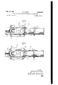
- the reference character IO designates a hopper of a railway car which has a fiat gate I! at the bottom for controlling the degree of opening therethrough.
- a rack l2 On the underside of the flat gate I I there is formed a rack l2 with which a pinion I3 engages for moving the gate from and to the closed position.
- the pinion I3 is fast on a shaft M which, as shown in Figure 1, has a square shank at its left hand end for receiving an operating head, shown generally at 15,
- the operating head I 5 includes a sleeve portion it which telescopes over the shank of the shaft [4.
- the sleeve portion It has asquare opening I! therethrough for non-rotatably receiving the square shank of the shaft I4.
- a pin or rivet- 8 extends rransverseiy through the sleevei't and the shaft l for-holding them" inseparable.
- A'- flange l9, formed integrally with the sleeve portion i6, is arranged tobear against acollar 20 extending sidewise from the lower portion of the hopper H]; as 'shownfto space the operating head 15 and act as a guide therefor.
- the operating head l5-- has an operating bar receiving portion that is indicated; generally, at 23 and shownmore clearlyin Figure 2.
- The-opcrating bar receiving portion 23 includes four angled shaped sections 24, Figure 3,--which extend lengthwise of the head 15 and shaft M in back tobackrelation and-they arespaced apart so as to .provide four sockets: or pockets 25 for receiving anoperating bar 26 at ninety degree intervals.
- Wall means 21 are provided on the respective sides of the axis of rotation of the operating head l5 and of the shaft M for interconnecting the respective angle shaped sections 24.
- these wall means or connecting sections are spaced lengthwise from each other so as to present axially spaced sections of the pockets 25 for receiving the operating bar 26 at an angle to the axis of rotation of the operating head [5 or the shaft Hi. It will be observed that this construction and arrangement of the sockets or pockets 25 is such that the operating bar 26 extends a substantial distance across the axis of rotation of the operating head l5 or the shaft [4 so that it can engage the former on opposite sides of said axis and provide a more certain operative interconnection therebetween.
- the angle of inclination of the four sockets or pockets 25 with respect to the axis of rotation of the operating head 15 is such that in any of them the operating bar 26 can be positioned substantially parallel to the adjacent side of the hopper ID as illustrated in Figure 1.
- a transverse wall 28 is formed integrally with the operating bar receiving portion 23 at the bottom of each of the sockets or pockets 25.
- a rectangular section 29 can be provided at the outermost end of the operating bar receiving portion 23 to permit the application thereto of a wrench or like tool if desired.
- means for rotating said shaft including an operating head adapted to be non-rotatably mounted on one end of said shaft with its longitudinal axis coincident with the axis of rotation thereof and including an operating bar receiving portion formed.
- each of said sections having an operating bar receiving pocket extending at an acute angle to the axis of rotation of said head and into and at least partly through the opposite section whereby two pairs of operating bar receiving pockets are provided in planes intersecting at right angles along said longitudinal axis and the exterior surface of each section containing two apertures, and wall means between the apertures in each section on one side defining a part of one of said operating bar receiving pockets of a pair and on the other side defining a part of the other bar receiving pocket of the same pair.
- means for rotating said shaft including an operating head adapted to be non-rotatably mounted on one end of said shaft with its longitudinal axis coincident with the axis of rotation thereof and including an operating bar receiving portion formed by four sections spaced 90 apart around and constituting an integral part of and extending lengthwise of said head, each of said sections having an operating bar receiving pocket extending at an acute angle to the axis of rotation of said head and into and at least partly through the opposite section whereby two pairs of operating bar receiving pockets are provided in planes intersecting at right angles along said longitudinal axis and the exterior surface of each section containing two apertures, wall means between the apertures in each section on one side defining a part of one of said operating bar receiving pockets of a pair and on the other side defining a part of the other bar receiving pocket of the same pair, and a transverse wall at the inner end of each pocket to limit the extent that
Description
G. B. DOREY Feb. 17, 1953 HEAD FOR GATE OPERATING MECHANISM FOR HOPPER CARS Filed Aug. 24, 1949 I 2 SHEETS-SHEET 1 I N V EN TOR. 060C965. florg,
Feb. 17, 1953 cs. B. DOREY 2,628,574
HEAD FOR GATE' OPERATING MECHANISM FOR HOPPER CARS Filed Aug. 24, 1949 2 SHEETS-SHEET 2 IN V EN TOR.
660696 5 Janey Patented Feb. 17, 1953 UNITEE PATENT HEAD FOR GATE: ornan'rnscliiiiaoniimsiu FOR HOPPER CABS I 4 dag ii]. btii w'tmoum; Quebec; allads, assignor; to Jlnterbrise Railway Equipment 0 m'pan'y', Chicago, 111., a corporation of Illinois Applicatien Aiigiist 2 1, 1949;; s'r a in). 112,031
ThisinVentiOn relates, erally, to gate openating. inechanisrris for hopper, type ,r'ailway cars, and it has particular) relation; to the head at.- t'ach'ed to the shaft rbrreqeivmg an operating bar toro'tate the same for opening and closing the gate. a
Among the objects of this invention are? To provide for receiving the operating bar on both sides of the axisof rotation of the shaft in order to provide a more certain operative connection therebetween; to receive. the ioperatingflbarain any one of a plurality of sockets oinpocketa which extend at an angle, across said a x L c f rotation; and to liniit' the extent that the operating bar can be inserted into any of the sockets or pockets. I I
Other objects of this invention will, in part, be obvious and in part appear hereinafter.
This invention is disclosed in the embodiment thereof shown in the accompanying drawing and it comprisesthe features of o'ns'tructiom combination of elements and arrangements of parts which will be exemplifiedin the construction hereinafter set forth and the scope of the application of which will be indicated in the appended Figure 3 is a view, in end elevation, of the operating head shown in Figure 2; and
Figures 4 and 5 are views in top plan and side elevation, respectively, of the operating head.
Referring now to the drawing it will be observed that the reference character IO designates a hopper of a railway car which has a fiat gate I! at the bottom for controlling the degree of opening therethrough. On the underside of the flat gate I I there is formed a rack l2 with which a pinion I3 engages for moving the gate from and to the closed position. The pinion I3 is fast on a shaft M which, as shown in Figure 1, has a square shank at its left hand end for receiving an operating head, shown generally at 15,
2 eatin (01. 105-365) which is constructe'd in accordance with this avenues.
The operating head I 5 includes a sleeve portion it which telescopes over the shank of the shaft [4. The sleeve portion It has asquare opening I! therethrough for non-rotatably receiving the square shank of the shaft I4. In addition a pin or rivet- 8 extends rransverseiy through the sleevei't and the shaft l for-holding them" inseparable. A'- flange l9, formed integrally with the sleeve portion i6, is arranged tobear against acollar 20 extending sidewise from the lower portion of the hopper H]; as 'shownfto space the operating head 15 and act as a guide therefor.
The operating head l5--has an operating bar receiving portion that is indicated; generally, at 23 and shownmore clearlyin Figure 2. The-opcrating bar receiving portion 23 includes four angled shaped sections 24, Figure 3,--which extend lengthwise of the head 15 and shaft M in back tobackrelation and-they arespaced apart so as to .provide four sockets: or pockets 25 for receiving anoperating bar 26 at ninety degree intervals. Wall means 21 are provided on the respective sides of the axis of rotation of the operating head l5 and of the shaft M for interconnecting the respective angle shaped sections 24. It will be observed that these wall means or connecting sections are spaced lengthwise from each other so as to present axially spaced sections of the pockets 25 for receiving the operating bar 26 at an angle to the axis of rotation of the operating head [5 or the shaft Hi. It will be observed that this construction and arrangement of the sockets or pockets 25 is such that the operating bar 26 extends a substantial distance across the axis of rotation of the operating head l5 or the shaft [4 so that it can engage the former on opposite sides of said axis and provide a more certain operative interconnection therebetween. This makes it unlikely that the operating bar 26 will slip out of the operating head l5 as might be the case if it were permitted to extend into the same only a limited extent such as to a position which does not go substantially beyond said axis of rotation. The angle of inclination of the four sockets or pockets 25 with respect to the axis of rotation of the operating head 15 is such that in any of them the operating bar 26 can be positioned substantially parallel to the adjacent side of the hopper ID as illustrated in Figure 1.
In order to limit the extent that the operating bar 26 can be inserted in any of the four sockets or pockets 25, a transverse wall 28 is formed integrally with the operating bar receiving portion 23 at the bottom of each of the sockets or pockets 25. Thus, while the construction is such as to permit the operating bar 26 to extend well beyond the axis of rotation of the operating head [5, there is a definite limit as to how far it can be inserted therethrough.
For convenience a rectangular section 29 can be provided at the outermost end of the operating bar receiving portion 23 to permit the application thereto of a wrench or like tool if desired.
Since certain changes can be made in the foregoing construction and different embodiments of the invention can be made without departing from the spirit and scope thereof, it is intended that all matter shown in the accompanying drawing and described hereinbefore shall be interpreted as illustrative and not in a limiting sense.
What is claimed as new is:
1. For combination with a shaft carrying pinion means cooperating with rack means on a gate used for controlling the opening through a hopper of a railway hopper type car, means for rotating said shaft including an operating head adapted to be non-rotatably mounted on one end of said shaft with its longitudinal axis coincident with the axis of rotation thereof and including an operating bar receiving portion formed. by four sections spaced 90 apart around and constituting an integral part of and extending lengt wise of said head, each of said sections having an operating bar receiving pocket extending at an acute angle to the axis of rotation of said head and into and at least partly through the opposite section whereby two pairs of operating bar receiving pockets are provided in planes intersecting at right angles along said longitudinal axis and the exterior surface of each section containing two apertures, and wall means between the apertures in each section on one side defining a part of one of said operating bar receiving pockets of a pair and on the other side defining a part of the other bar receiving pocket of the same pair.
2. For combination with a shaft carrying pinion means cooperating with rack means on a gate used for controlling the opening through a hopper of a railway hopper type car, means for rotating said shaft including an operating head adapted to be non-rotatably mounted on one end of said shaft with its longitudinal axis coincident with the axis of rotation thereof and including an operating bar receiving portion formed by four sections spaced 90 apart around and constituting an integral part of and extending lengthwise of said head, each of said sections having an operating bar receiving pocket extending at an acute angle to the axis of rotation of said head and into and at least partly through the opposite section whereby two pairs of operating bar receiving pockets are provided in planes intersecting at right angles along said longitudinal axis and the exterior surface of each section containing two apertures, wall means between the apertures in each section on one side defining a part of one of said operating bar receiving pockets of a pair and on the other side defining a part of the other bar receiving pocket of the same pair, and a transverse wall at the inner end of each pocket to limit the extent that the operating bar can be inserted therein.
GEORGE B. DOREY.
REFERENCES CITED The following references are of record in the file of this patent:
UNITED STATES PATENTS Number Name Date 687,947 Weston Dec. 3, 1901 904,819 Troeller Nov. 24, 1908 1,307,140 Morgans June 17, 1919 2,072,292 Campbell Mar. 2, 1937 2,300,406 Curtis Nov. 3, 1942 2,306,148 Woodruff Dec. 22, 1942 2,361,559 Mekelburg Oct. 31, 1944 2,386,702 McBride Oct. 9, 1945
Priority Applications (1)
| Application Number | Priority Date | Filing Date | Title |
|---|---|---|---|
| US112031A US2628574A (en) | 1949-08-24 | 1949-08-24 | Head for gate operating mechanism for hopper cars |
Applications Claiming Priority (1)
| Application Number | Priority Date | Filing Date | Title |
|---|---|---|---|
| US112031A US2628574A (en) | 1949-08-24 | 1949-08-24 | Head for gate operating mechanism for hopper cars |
Publications (1)
| Publication Number | Publication Date |
|---|---|
| US2628574A true US2628574A (en) | 1953-02-17 |
Family
ID=22341755
Family Applications (1)
| Application Number | Title | Priority Date | Filing Date |
|---|---|---|---|
| US112031A Expired - Lifetime US2628574A (en) | 1949-08-24 | 1949-08-24 | Head for gate operating mechanism for hopper cars |
Country Status (1)
| Country | Link |
|---|---|
| US (1) | US2628574A (en) |
Cited By (2)
| Publication number | Priority date | Publication date | Assignee | Title |
|---|---|---|---|---|
| US2869480A (en) * | 1950-03-20 | 1959-01-20 | Entpr Railway Equipment Co | Operating mechanism for closure member of a discharge outlet assembly |
| EP3548355A4 (en) * | 2016-12-02 | 2020-08-05 | Chambers, Quintin | Rail car key adaptor tool |
Citations (8)
| Publication number | Priority date | Publication date | Assignee | Title |
|---|---|---|---|---|
| US687947A (en) * | 1898-02-19 | 1901-12-03 | Thomas A Weston | Wrench. |
| US904819A (en) * | 1907-07-17 | 1908-11-24 | Wilhelm Troeller | Means for attaching stirring-arms to shafts in mechanical roasting-furnace. |
| US1307140A (en) * | 1919-06-17 | Printer s furniture | ||
| US2072292A (en) * | 1933-06-23 | 1937-03-02 | Entpr Railway Equipment Co | Load discharging car |
| US2300406A (en) * | 1940-08-02 | 1942-11-03 | Sullivan Machinery Co | Operating handle |
| US2306148A (en) * | 1941-07-16 | 1942-12-22 | Lcl Corp | Freight container |
| US2361559A (en) * | 1943-10-28 | 1944-10-31 | Cutler Hammer Inc | Handle attaching device |
| US2386702A (en) * | 1942-06-27 | 1945-10-09 | American Car & Foundry Co | Hopper discharge |
-
1949
- 1949-08-24 US US112031A patent/US2628574A/en not_active Expired - Lifetime
Patent Citations (8)
| Publication number | Priority date | Publication date | Assignee | Title |
|---|---|---|---|---|
| US1307140A (en) * | 1919-06-17 | Printer s furniture | ||
| US687947A (en) * | 1898-02-19 | 1901-12-03 | Thomas A Weston | Wrench. |
| US904819A (en) * | 1907-07-17 | 1908-11-24 | Wilhelm Troeller | Means for attaching stirring-arms to shafts in mechanical roasting-furnace. |
| US2072292A (en) * | 1933-06-23 | 1937-03-02 | Entpr Railway Equipment Co | Load discharging car |
| US2300406A (en) * | 1940-08-02 | 1942-11-03 | Sullivan Machinery Co | Operating handle |
| US2306148A (en) * | 1941-07-16 | 1942-12-22 | Lcl Corp | Freight container |
| US2386702A (en) * | 1942-06-27 | 1945-10-09 | American Car & Foundry Co | Hopper discharge |
| US2361559A (en) * | 1943-10-28 | 1944-10-31 | Cutler Hammer Inc | Handle attaching device |
Cited By (2)
| Publication number | Priority date | Publication date | Assignee | Title |
|---|---|---|---|---|
| US2869480A (en) * | 1950-03-20 | 1959-01-20 | Entpr Railway Equipment Co | Operating mechanism for closure member of a discharge outlet assembly |
| EP3548355A4 (en) * | 2016-12-02 | 2020-08-05 | Chambers, Quintin | Rail car key adaptor tool |
Similar Documents
| Publication | Publication Date | Title |
|---|---|---|
| US2628574A (en) | Head for gate operating mechanism for hopper cars | |
| US2155463A (en) | Freight car | |
| DE2133901A1 (en) | Engine suspension for aircraft | |
| DE461050C (en) | Coupling head for automatic railway center buffer couplings | |
| CH263453A (en) | Ampoule packaging. | |
| DE540786C (en) | Brush holder for electrical machines with at least one brush guided in a brush pocket with brush edges parallel to the barrel axis | |
| US2869480A (en) | Operating mechanism for closure member of a discharge outlet assembly | |
| US1955803A (en) | Printing device | |
| US2915860A (en) | Journal bearing lubricators | |
| DE905001C (en) | Drilling tool, especially for rock | |
| USD65219S (en) | Stanley g | |
| Mayerova | Work motivation in some railway transport professions. | |
| DE673454C (en) | Direction indicators, in particular for motor vehicles | |
| US1869945A (en) | Holder for socket wrench sets | |
| DE397263C (en) | Flat bottom self unloader | |
| USD192063S (en) | Bulk lading car | |
| DE758100C (en) | Composite excavator for high and low cut | |
| US2626716A (en) | Car coupler centering device | |
| US1468359A (en) | Closure for discharge apertures in packages | |
| USD193286S (en) | Railway car for transporting vehicles | |
| USD159044S (en) | Bushnell impact wrench power unit | |
| DE938492C (en) | Movable rerailing device for conveyor, field and railway wagons | |
| US1512030A (en) | System of transportation | |
| DE815440C (en) | Envelope | |
| US2605669A (en) | Draft key retainer lock |