US2626711A - Adjustable peg rack - Google Patents
Adjustable peg rack Download PDFInfo
- Publication number
- US2626711A US2626711A US63818A US6381848A US2626711A US 2626711 A US2626711 A US 2626711A US 63818 A US63818 A US 63818A US 6381848 A US6381848 A US 6381848A US 2626711 A US2626711 A US 2626711A
- Authority
- US
- United States
- Prior art keywords
- peg
- supporting
- flanges
- rack
- spaced
- Prior art date
- Legal status (The legal status is an assumption and is not a legal conclusion. Google has not performed a legal analysis and makes no representation as to the accuracy of the status listed.)
- Expired - Lifetime
Links
- 238000003754 machining Methods 0.000 description 2
- 239000000463 material Substances 0.000 description 2
- 230000004048 modification Effects 0.000 description 2
- 238000012986 modification Methods 0.000 description 2
- 238000005452 bending Methods 0.000 description 1
- 230000015572 biosynthetic process Effects 0.000 description 1
- 239000011248 coating agent Substances 0.000 description 1
- 238000000576 coating method Methods 0.000 description 1
- 238000005553 drilling Methods 0.000 description 1
- 230000001788 irregular Effects 0.000 description 1
- 239000004922 lacquer Substances 0.000 description 1
- 239000010687 lubricating oil Substances 0.000 description 1
- 238000004519 manufacturing process Methods 0.000 description 1
- 239000002184 metal Substances 0.000 description 1
- 230000000284 resting effect Effects 0.000 description 1
Images

Classifications
-
- B—PERFORMING OPERATIONS; TRANSPORTING
- B62—LAND VEHICLES FOR TRAVELLING OTHERWISE THAN ON RAILS
- B62B—HAND-PROPELLED VEHICLES, e.g. HAND CARTS OR PERAMBULATORS; SLEDGES
- B62B3/00—Hand carts having more than one axis carrying transport wheels; Steering devices therefor; Equipment therefor
- B62B3/006—Hand carts having more than one axis carrying transport wheels; Steering devices therefor; Equipment therefor for stacking objects like trays, bobbins, chains
-
- F—MECHANICAL ENGINEERING; LIGHTING; HEATING; WEAPONS; BLASTING
- F16—ENGINEERING ELEMENTS AND UNITS; GENERAL MEASURES FOR PRODUCING AND MAINTAINING EFFECTIVE FUNCTIONING OF MACHINES OR INSTALLATIONS; THERMAL INSULATION IN GENERAL
- F16B—DEVICES FOR FASTENING OR SECURING CONSTRUCTIONAL ELEMENTS OR MACHINE PARTS TOGETHER, e.g. NAILS, BOLTS, CIRCLIPS, CLAMPS, CLIPS OR WEDGES; JOINTS OR JOINTING
- F16B2200/00—Constructional details of connections not covered for in other groups of this subclass
- F16B2200/20—Connections with hook-like parts gripping behind a blind side of an element to be connected
Definitions
- This invention trlates to a peg rack for use in .handling materials, and, more particularly, to an improved peg rack structure on which the position of article supporting pegs may be readily adjusted in accordance with the size and shape of the articles to be mounted on the pegs.
- one of 'the principal objects of this invention is to provide a peg rack in which the position of article supporting pegs thereon may be readily adjusted.
- Another object of this invention is to provide a novel form of peg rack having peg supporting members in vertically extending spaced parallel planes, the spaced peg supporting members having pairs of aligned openings therein in which the end of the peg is receivable to provide a support for the peg at points spaced from each other and adjacent the end thereof.
- a further object of the invention is to provide a novel peg rack in which the peg "supporting members are provided by a plurality of U -'shaped channels having spaced flanges in which a plurality of pairs of aligned openings are formed for the reception of the end of .an articl supporting peg to be mounted thereon.
- a still further object of this invention is to provide a novel form of peg structure for limiting its movement in an endwise direction with respect to supporting structure therefor.
- Another object of the invention is to provide a peg structure of the character just referred to in which the structure for limiting endwise movement of the peg comprises an abutting shoulder on the peg and a releasable detent both en a eable with the peg supporting structure on which Cal 2 r the peg is mounted and which are respectively operable to prevent endwise movement of the peg in opposite directions.
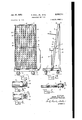
- Fig. l is a front "elevational viewoi a peg rack. constructed in accordance with the principlesoi this invention
- Fig. 2 is a side elevational View of the rack shown in Fig. 1:;
- Fig. 3 is an enlarged iragmentary plan view illustrating the preferred embodiment "of peg structure; r
- Fig. 4 is a fragmentary sectional view or the peg structure shown in Fig. 3.; N
- Fig. 5 is a fragmentary sectional View showing the manner in which the peg structure of Figs. 3 and 4 is received in a pair of aligned openings formed in the flanges of one of theipeg supporting channels shown inFigs. 1 and'2;
- Fig. '6 is an elevational View of a'modified form of peg structure
- Fig. 7 is an end view of the peg'shown in Fig. 6.
- Fig. .8 is a fragmentary elevational View of a peg supporting channel illustrating the shape of the peg supporting openings therein for the peg shown in Fig. 6 and 7;
- Figs. '9 and 10 are, respectively, fragmentary side and elevational views of modified structures for securing the pegs in position with respect to supporting channels. 7
- the structure of the peg rack isshown-in Figs. 1 and v2 in which the numeral l desig-nates a reinforced base mounted on casters 2, and having .a handle 3 pivoted thereto for facilitating its movement from one position to another.
- a vertically extending support 4 is mounted on the base I and comprises side angle sections 5 connected at their upper ends by a top angle section 6, the angle sections 5 and 6 being preferably formed from a common strip of angle section stock.
- the peg supporting structure is designated as a whole by thenumeral l and comprises aplurality of spaced, parallel U-shaped channels '8.
- the channel sections '8 have their upper ends secured in spaced relation to an angle section '9 and their lower ends similarly secured insp'aced relation to an angle section It.
- the channei sections 8 are braced by a center strip l l welded to the front 'flanges [2 or th channels 8 and an angle section l3 Welded to the back flanges I 4 of the channels 8.
- the peg supporting structure 'I thus constitutes a unit comprising the parallel channel sections 3 and their securing parts 9, I0, I I, and I3.
- the peg supporting structure I is mounted in an inclined position on the portable base I, as shown in Fig. 2, by securing the angle section It to the base I at a point spaced from the lower end of the vertically extending support 4.
- the angle section 9 at the upper end of the peg supporting structure I is secured to the angle section of the vertical supporting structure 4 thus providing 'a support for the upper ends of the peg supporting structure I.
- Bracin members I5 are secured to the center portion of the channels 8 defining the sides of the supporting structure I and to the center portion of the flanges 5 of the vertically extending support 4 for preventing movement of the supporting structure I out of its inclined position with respect to the support 4.
- the flanges I2 and I4 of the channel sections 8 providevsupporting members in spaced parallel plane which extend substantially vertically upward from the base I.
- the spaced parallel supporting members I2 and I4 provide a peg support which has supporting engagement with the peg at spaced points adjacent one end thereof.
- the use of the channels 8 providing the spaced parallel supporting members I2 and I4 illustrates the preferred embodiment of the invention, and that such spaced supporting members may be provided by modified structures without departing from the principles of this invention. More particularly, and by way of example, the spaced supporting members I 2 and I 4 may be provided by two spaced parallel sheet-metal plates mounted in spaced relation. However, the use of channels 8 is preferred by reason of the rigidity provided thereby.
- each of the channels 8 is provided with a plurality of pairs of aligned openings I6, formed respectively in the flanges I2 and I4, for the reception of an end of the peg, the aligned relation of the openings I6 being best shown in Fig. 5.
- the opening in the front flange I2 has a larger diameter than the opening in the back flange I4.
- the opening in the flange I2 preferably has a diameter such that a peg I'I inserted therethrough has a close fit in the flange I2.
- the end I8 of the peg I I has a reduced diameter corresponding to the size of the opening in the back flange I4 of the channel 8.
- a shoulder or abutment I9 is provided on the peg II for engagement with the flange I4 in the area about the opening I6 therein through which the small end I8 of the peg IT projects.
- the shoulder I9 thus acts as an abutment for limiting endwise movement of the peg II to the right as viewed in Fig. 5.
- a releasable detent 20 is provided on the small end I8 for preventing accidental movement of the peg II to the left as viewed in Fig. 5.
- the detent 20 is a sphere or ball having a spring 2! for biasing it to an upper position with respect to an opening 22 drilled in the end iii.
- the detent is constructed by first drilling the cylindrical opening 22 into which the spring 2
- the small end I8 is moved endwise through any selected pair of openings I6 to the position shown in Fig. 5.
- the ball detent 20 is forced inwardly against the action of its biasing spring 2
- the ball detent 20 is moved by its biasing spring to its outer position in which it becomes operable to prevent accidental movement of the small end I 8 to the left as viewed in Figure 5.
- the peg I! may be withdrawn intentionally from the aligned openings I 6 by applying sufficient force thereto to cam the detent 20 inwardly against the action of its spring 2I so that the part I3 may be withdrawn from the opening in the flange I4.
- the rack support I provides a support for a large number of pegs corresponding to the number of aligned openings I6 in the flanges of the channel sections 8. Obviously, a lesser number of pegs [I may be provided.
- the positional arrangement of a peg may be adjusted quite easily on the support I in accordance with the selection of the aligned open ings in which the peg is entered. Attention is particularly invited to the fact that the provision of the shoulder I 9 on the peg I! and the detent 25 cooperate to limit endwise movement of the pe when mounted on a rack.
- a heavy weight may be mounted on the peg without distorting the structure of the supporting members I2 and I4 and Without damage to its supporting connection on the rack.
- This spacedv supporting arrangement is also effective to prevent bending of the peg between its points of support in such manner as to interfere with removal of the peg from the support.
- the mounting of the supporting rack I on the base I provides a portable support by which the rack I, with or without articles supported thereon, may be readily moved from one position to another.
- the peg illustrated in Figs. 6, 7, and 8 may be employed in place of the cylindrical pegs II described above.
- the peg illustrated in Figs. 6 and '7 comprises an angle section 25 which i rigidly secured to a rod 26 having a reduced end 21 for reception in a pair of aligned openings 28 formed in the flanges of a channel support 8.
- the reduced end 21 is a cylindrical section having a segmental portion removed to provide a flat 29 extending axially along one side thereof.
- the aligned openings 22 are shaped with a flat surface 30 to conform with the shape of the reduced end 21 so that, when the end, 21 is inserted through the openings 28, the surfaces 29 and 30 will engage to prevent turning :movement of the part 21 in the openings 28.
- the angle section 25 supported on the rod 25 will thus be effectively prevented from turning or changing its angular position on the supporting structure.
- Figs. 9 and 10 there is shown a modified form of detent mechanism for securing the pegs against movement out of a position supported by channels 8.
- the structure shown in these fi ures is essentially the same as that described in connection with Figs. 1 through 5 and like numerals have been employed to designate like parts.
- the function of the ball detent is performed by locking bars 32.
- the locking bars 32 have their ends supported in brackets 33 secured to the end channel members 8 and are provided with a notch 34 for interlocking engagement with the bottom portion 35 of the brackets 33 to prevent endwise movement of the locking bars 32.
- the lower edge 36 will be positioned in front of the openings I6 in the back flange M.
- the small end 18 of the peg I1 is undercut as at 31 to provide a recess into which the lower edge 36 of the locking bar 32 may move.
- movement of the peg I! to the left as viewed in Fig. 9 will be prevented.
- a slat-like supporting structure comprising a pair of spaced end angle sections each having a flange in a common plane and an upstanding flange in spaced parallel planes which are substantially normal to said common plane, a plurality of parallel U-shaped channel sections extending between and normal to said angle sections with the ends thereof connected to said upstanding flanges, said channel sections having parallel webs perpendicular to said common plane with each channel section web having upper and lower parallel flanges, the ends of each of said lower flanges resting on one of said angle section flanges in said common plane, said channel sections being spaced with their upper flanges forming parallel supporting surfaces having narrow elongated slot therebetween, said parallel supporting surfaces cooperating to provide a slatlike support on which an article may be supported by a plurality of said parallel supporting surfaces, said upper and lower flanges on each of said channel sections having a plurality of pairs of aligned openings therein, said openings in said upper f
- a slat-like supporting structure comprising a pair of transversely extending end structural sections, a plurality of parallel U-shaped channel sections extending between and normal to said structural sections, the ends of said channel sections being rigidly secured to said structural sections, said channel sections having parallel webs with each web having upper and lower parallel flanges, all of said upper flanges and all of said lower flanges being respectively positioned in spaced parallel planes, said channel sections being spaced with their upper flanges forming parallel supporting surfaces having elongated slots therebetween, said parallel supporting surfaces cooperating to provide a slatlike support on which an article may be supported by a plurality of said parallel supporting surfaces, said upper and lower flanges on each of said channel sections having a plurality of pairs of aligned openings therein, and a peg support movable axially endwise through a selected pair of said openings to a position supported by the flanges of one of said channel sections so that an article may be
Landscapes
- Engineering & Computer Science (AREA)
- Chemical & Material Sciences (AREA)
- Combustion & Propulsion (AREA)
- Transportation (AREA)
- Mechanical Engineering (AREA)
- Warehouses Or Storage Devices (AREA)
Description
Jan. 27, 1953 s. SAUL, JR., ETAL 7 2,626,711
ADJUSTABLE PEG RACK Filed Dec. 6, 1948 2 SHEETS-SHEET 1 INVENTORS SAMUEL SAUL JR. LLOYD H.FENSTERMAKER.
ATTORNEYS.
Jan. 27, 1953 Filed Dec. 6, 1948 s. SAUL, JR. ETAL ADJUSTABLE PEG RACK 2 SHEETSSHEET 2 Fi .7. Fig.5.
INVENTORS.
SAMUEL SAUL JR LLOYD H. FENSTERMAKER.
ATTORNEYS.
Patented Jan. 27, 1953 ADJU STABLE PEG BACK Samuel Saul, Lin, and Lloyd H Ferrsterma ker,
Pittsburgh-Pa; said Fenstermairer assignor to said Saul Appiicationllecember c, 1948, semi-aim. 63,818
(01. err- 12 2 Claims.
This inventiontrlates to a peg rack for use in .handling materials, and, more particularly, to an improved peg rack structure on which the position of article supporting pegs may be readily adjusted in accordance with the size and shape of the articles to be mounted on the pegs.
In industrial operations, articles are "frequently encountered which have such an irregular size and shape that they may not be conveniently supported on a fiat surface. It frequently hapfpens that such articles have openings therein by which they may be readily supported 'by hanging on a peg. Such articles are commonly encountered .in "machine shops where a plurality of machining operations are to be performed on the article in its fabrication. In addition to forming "a convenient support for such articles, a'pe'g has the additional advantage 'of enabling ade- .quate drainage of lubricating oil therefrom while being transported between machines for successive machining operations. :Peg supports are also desirable from the standpoint of "drainage where articles have been provided with :aprotec- 'tive coating of lacquer or other materials.
Since the number and arrangement of -pegs necessary on'a'r'ack will vary with the size, weight, and shape of the articles being handled, one of 'the principal objects of this invention is to provide a peg rack in which the position of article supporting pegs thereon may be readily adjusted.
Another object of this invention is to provide a novel form of peg rack having peg supporting members in vertically extending spaced parallel planes, the spaced peg supporting members having pairs of aligned openings therein in which the end of the peg is receivable to provide a support for the peg at points spaced from each other and adjacent the end thereof.
A further object of the invention is to provide a novel peg rack in which the peg "supporting members are provided by a plurality of U -'shaped channels having spaced flanges in which a plurality of pairs of aligned openings are formed for the reception of the end of .an articl supporting peg to be mounted thereon.
A still further object of this invention is to provide a novel form of peg structure for limiting its movement in an endwise direction with respect to supporting structure therefor.
Another object of the invention is to provide a peg structure of the character just referred to in which the structure for limiting endwise movement of the peg comprises an abutting shoulder on the peg and a releasable detent both en a eable with the peg supporting structure on which Cal 2 r the peg is mounted and which are respectively operable to prevent endwise movement of the peg in opposite directions.
"Other objects and advantages of the'invention will become apparent from the following description.
In the drawings, there is sh'owna prefer-red embodiment of the invention. In this showing:
Fig. l is a front "elevational viewoi a peg rack. constructed in accordance with the principlesoi this invention;
Fig. 2 is a side elevational View of the rack shown in Fig. 1:; I
Fig. 3 is an enlarged iragmentary plan view illustrating the preferred embodiment "of peg structure; r
Fig. 4 is a fragmentary sectional view or the peg structure shown in Fig. 3.; N
Fig. 5 is a fragmentary sectional View showing the manner in which the peg structure of Figs. 3 and 4 is received in a pair of aligned openings formed in the flanges of one of theipeg supporting channels shown inFigs. 1 and'2;
Fig. '6 is an elevational View of a'modified form of peg structure; n
Fig. 7 is an end view of the peg'shown in Fig. 6.;
Fig. .8 is a fragmentary elevational View of a peg supporting channel illustrating the shape of the peg supporting openings therein for the peg shown in Fig. 6 and 7; and
Figs. '9 and 10 are, respectively, fragmentary side and elevational views of modified structures for securing the pegs in position with respect to supporting channels. 7
The structure of the peg rack isshown-in Figs. 1 and v2 in which the numeral l desig-nates a reinforced base mounted on casters 2, and having .a handle 3 pivoted thereto for facilitating its movement from one position to another. A vertically extending support 4 is mounted on the base I and comprises side angle sections 5 connected at their upper ends by a top angle section 6, the angle sections 5 and 6 being preferably formed from a common strip of angle section stock.
The peg supporting structure is designated as a whole by thenumeral l and comprises aplurality of spaced, parallel U-shaped channels '8. The channel sections '8 have their upper ends secured in spaced relation to an angle section '9 and their lower ends similarly secured insp'aced relation to an angle section It. The channei sections 8 are braced by a center strip l l welded to the front 'flanges [2 or th channels 8 and an angle section l3 Welded to the back flanges I 4 of the channels 8. The peg supporting structure 'I thus constitutes a unit comprising the parallel channel sections 3 and their securing parts 9, I0, I I, and I3.
The peg supporting structure I is mounted in an inclined position on the portable base I, as shown in Fig. 2, by securing the angle section It to the base I at a point spaced from the lower end of the vertically extending support 4. The angle section 9 at the upper end of the peg supporting structure I is secured to the angle section of the vertical supporting structure 4 thus providing 'a support for the upper ends of the peg supporting structure I. Bracin members I5 are secured to the center portion of the channels 8 defining the sides of the supporting structure I and to the center portion of the flanges 5 of the vertically extending support 4 for preventing movement of the supporting structure I out of its inclined position with respect to the support 4. The flanges I2 and I4 of the channel sections 8 providevsupporting members in spaced parallel plane which extend substantially vertically upward from the base I. In a manner to be described, the spaced parallel supporting members I2 and I4 provide a peg support which has supporting engagement with the peg at spaced points adjacent one end thereof. It will be understood that the use of the channels 8 providing the spaced parallel supporting members I2 and I4 illustrates the preferred embodiment of the invention, and that such spaced supporting members may be provided by modified structures without departing from the principles of this invention. More particularly, and by way of example, the spaced supporting members I 2 and I 4 may be provided by two spaced parallel sheet-metal plates mounted in spaced relation. However, the use of channels 8 is preferred by reason of the rigidity provided thereby.
In order to provide a support for pegs, each of the channels 8 is provided with a plurality of pairs of aligned openings I6, formed respectively in the flanges I2 and I4, for the reception of an end of the peg, the aligned relation of the openings I6 being best shown in Fig. 5. Referring specifically to Fig. 5, it will be noted that the opening in the front flange I2 has a larger diameter than the opening in the back flange I4. The opening in the flange I2 preferably has a diameter such that a peg I'I inserted therethrough has a close fit in the flange I2. The end I8 of the peg I I has a reduced diameter corresponding to the size of the opening in the back flange I4 of the channel 8. In this manner, a shoulder or abutment I9 is provided on the peg II for engagement with the flange I4 in the area about the opening I6 therein through which the small end I8 of the peg IT projects. The shoulder I9 thus acts as an abutment for limiting endwise movement of the peg II to the right as viewed in Fig. 5. A releasable detent 20 is provided on the small end I8 for preventing accidental movement of the peg II to the left as viewed in Fig. 5.
The structure of the releasable detent 20 will be best understood by referring to the showings of Figs. 3 and 4. From this showing it will be noted that the detent 20 is a sphere or ball having a spring 2! for biasing it to an upper position with respect to an opening 22 drilled in the end iii. The detent is constructed by first drilling the cylindrical opening 22 into which the spring 2| is placed. The balldetentZU is then forced into the opening 22 bycompressing the spring 2|. To
hold-the'detent against movement completely 4 out of the opening 22, the surface of the small end I8 is notched, as at 23, on opposite sides of the opening 22. This provides a restriction at the mouth of the opening 22 for limiting movement of the ball detent 20 out of the opening 22 by the biasing spring 2 I.
To mount the peg II on the supporting rack I, the small end I8 is moved endwise through any selected pair of openings I6 to the position shown in Fig. 5. As the small end I8 moves through the opening in the back flange I4, the ball detent 20 is forced inwardly against the action of its biasing spring 2|. After the ball detent has moved to a position behind the flange I4 and with the shoulder IS in abutting engagement with the flange I4, the ball detent 20 is moved by its biasing spring to its outer position in which it becomes operable to prevent accidental movement of the small end I 8 to the left as viewed in Figure 5. The peg I! may be withdrawn intentionally from the aligned openings I 6 by applying sufficient force thereto to cam the detent 20 inwardly against the action of its spring 2I so that the part I3 may be withdrawn from the opening in the flange I4.
From the foregoing, it will be apparent that the rack support I provides a support for a large number of pegs corresponding to the number of aligned openings I6 in the flanges of the channel sections 8. Obviously, a lesser number of pegs [I may be provided. In addition, it will be apparent that the positional arrangement of a peg may be adjusted quite easily on the support I in accordance with the selection of the aligned open ings in which the peg is entered. Attention is particularly invited to the fact that the provision of the shoulder I 9 on the peg I! and the detent 25 cooperate to limit endwise movement of the pe when mounted on a rack. Attention is also directed to the fact that the provision of the spaced parallel supporting members I2 and I4 provides a peg support which has supporting engagement with the peg at spaced points along its length. By providing a support having supporting engagement with the peg at spaced points, a heavy weight may be mounted on the peg without distorting the structure of the supporting members I2 and I4 and Without damage to its supporting connection on the rack. This spacedv supporting arrangement is also effective to prevent bending of the peg between its points of support in such manner as to interfere with removal of the peg from the support. It will also be apparent that the mounting of the supporting rack I on the base I provides a portable support by which the rack I, with or without articles supported thereon, may be readily moved from one position to another.
In the case of articles which must be supported in a predetermined position, the structure illustrated in Figs. 6, 7, and 8 may be employed in place of the cylindrical pegs II described above. The peg illustrated in Figs. 6 and '7 comprises an angle section 25 which i rigidly secured to a rod 26 having a reduced end 21 for reception in a pair of aligned openings 28 formed in the flanges of a channel support 8. The reduced end 21 is a cylindrical section having a segmental portion removed to provide a flat 29 extending axially along one side thereof. The aligned openings 22 are shaped with a flat surface 30 to conform with the shape of the reduced end 21 so that, when the end, 21 is inserted through the openings 28, the surfaces 29 and 30 will engage to prevent turning :movement of the part 21 in the openings 28. The angle section 25 supported on the rod 25 will thus be effectively prevented from turning or changing its angular position on the supporting structure.
In Figs. 9 and 10, there is shown a modified form of detent mechanism for securing the pegs against movement out of a position supported by channels 8. The structure shown in these fi ures is essentially the same as that described in connection with Figs. 1 through 5 and like numerals have been employed to designate like parts. In the modification shown in Figs. 9 and 10, the function of the ball detent is performed by locking bars 32. The locking bars 32 have their ends supported in brackets 33 secured to the end channel members 8 and are provided with a notch 34 for interlocking engagement with the bottom portion 35 of the brackets 33 to prevent endwise movement of the locking bars 32. When the locking bars 32 are mounted on the brackets 33, as shown in Figs. 9 and 10, the lower edge 36 will be positioned in front of the openings I6 in the back flange M. The small end 18 of the peg I1 is undercut as at 31 to provide a recess into which the lower edge 36 of the locking bar 32 may move. When the bar 32 is positioned in the recess 31, movement of the peg I! to the left as viewed in Fig. 9 will be prevented. In order to withdraw the peg [1, it is first necessary to elevate the locking bar 32 to move the lower edge 36 out of the recess 31.
While we have illustrated and described one specific embodiment of our invention, it will be understood that this is merely by way of illustration, and that various changes and modifications may be made therein within the contemplation of our invention and under the scope of the following claims.
We claim:
1. In a peg rack, a slat-like supporting structure comprising a pair of spaced end angle sections each having a flange in a common plane and an upstanding flange in spaced parallel planes which are substantially normal to said common plane, a plurality of parallel U-shaped channel sections extending between and normal to said angle sections with the ends thereof connected to said upstanding flanges, said channel sections having parallel webs perpendicular to said common plane with each channel section web having upper and lower parallel flanges, the ends of each of said lower flanges resting on one of said angle section flanges in said common plane, said channel sections being spaced with their upper flanges forming parallel supporting surfaces having narrow elongated slot therebetween, said parallel supporting surfaces cooperating to provide a slatlike support on which an article may be supported by a plurality of said parallel supporting surfaces, said upper and lower flanges on each of said channel sections having a plurality of pairs of aligned openings therein, said openings in said upper flanges being larger than the openings in said lower flanges, and a peg support movable endwise through a selected pair of said openings to a position supported by the flanges of one of said channel sections so that an article may be hung thereon and prevented from sliding movement over said slat-like supporting surface, said peg having a body portion of a size such that it will move through said larger openings but have a snug fit therein, and a reduced end projecting from said body portion for movement through said smaller openings, the formation of said peg with a reduced end providing ashoulder at the end of said peg body portion engageable with one of said lower flanges in an area around an opening therein to limit endwise movement of said peg to a mounted position.
2. In a peg rack, a slat-like supporting structure comprising a pair of transversely extending end structural sections, a plurality of parallel U-shaped channel sections extending between and normal to said structural sections, the ends of said channel sections being rigidly secured to said structural sections, said channel sections having parallel webs with each web having upper and lower parallel flanges, all of said upper flanges and all of said lower flanges being respectively positioned in spaced parallel planes, said channel sections being spaced with their upper flanges forming parallel supporting surfaces having elongated slots therebetween, said parallel supporting surfaces cooperating to provide a slatlike support on which an article may be supported by a plurality of said parallel supporting surfaces, said upper and lower flanges on each of said channel sections having a plurality of pairs of aligned openings therein, and a peg support movable axially endwise through a selected pair of said openings to a position supported by the flanges of one of said channel sections so that an article may be hung thereon and prevented from sliding over said slat-like supporting surface.
SAMUEL SAUL, JR. LLOYD H. FENSTERMAKER.
REFERENCES CITED The following references are of record in the file of this patent:
UNITED STATES PATENTS Number Name Date 504,729 Keller Sept. 12, 1893 613,760 Cronin Nov. 8, 1898 670,144 Bond Mar. 19, 1901 686,063 Hecker Nov. 5, 1901 931,669 Babcock Aug. 17, 1909 1,380,570 Lehman June 7, 1921 1,698,318 Norton Jan. 8, 1929 1,867,611 Borrmann July 19, 1932 1,888,155 Biedinger Nov. 15, 1932 1,992,901 McIntosh Feb. 26, 1935 2,043,841 Stevens June 9, 1936 2,100,421 Wupper Nov. 30, 1937 2,246,692 Ohme June 24, 1941 2,421,894 Lee June 10, 1947 2,451,674 Hade Oct. 19, 1948
Priority Applications (1)
| Application Number | Priority Date | Filing Date | Title |
|---|---|---|---|
| US63818A US2626711A (en) | 1948-12-06 | 1948-12-06 | Adjustable peg rack |
Applications Claiming Priority (1)
| Application Number | Priority Date | Filing Date | Title |
|---|---|---|---|
| US63818A US2626711A (en) | 1948-12-06 | 1948-12-06 | Adjustable peg rack |
Publications (1)
| Publication Number | Publication Date |
|---|---|
| US2626711A true US2626711A (en) | 1953-01-27 |
Family
ID=22051700
Family Applications (1)
| Application Number | Title | Priority Date | Filing Date |
|---|---|---|---|
| US63818A Expired - Lifetime US2626711A (en) | 1948-12-06 | 1948-12-06 | Adjustable peg rack |
Country Status (1)
| Country | Link |
|---|---|
| US (1) | US2626711A (en) |
Cited By (16)
| Publication number | Priority date | Publication date | Assignee | Title |
|---|---|---|---|---|
| US2814402A (en) * | 1955-01-07 | 1957-11-26 | Harold J Schaefer | Apparatus for handling block-type material |
| US3064992A (en) * | 1960-03-31 | 1962-11-20 | Hoof Products Company | Utility carts with article supporting racks |
| US3291318A (en) * | 1965-02-24 | 1966-12-13 | United States Steel Corp | Apparatus for storing hoisting equipment |
| US3442396A (en) * | 1966-09-26 | 1969-05-06 | Eckrich Peter & Sons | Fixture for displaying packaged products |
| US3567036A (en) * | 1969-03-06 | 1971-03-02 | Hormel & Co Geo A | Reseal product display rack |
| US3844231A (en) * | 1971-05-14 | 1974-10-29 | Myers Ind Inc | Sandwich panel structures for supporting shelves |
| US4221395A (en) * | 1978-11-24 | 1980-09-09 | James Carte | Hurdle hauler |
| US4223862A (en) * | 1978-11-20 | 1980-09-23 | Doughty Val J | Patient support apparatus |
| US4606466A (en) * | 1984-04-02 | 1986-08-19 | Cannon Equipment Company | Pegbar display device having a carrier for graphic identification |
| US5094352A (en) * | 1991-05-06 | 1992-03-10 | Green Sr James F | Portable rack for holding pots and pans and the like |
| US20040130113A1 (en) * | 2003-01-06 | 2004-07-08 | Iwanicki Mark A. | Segmented cart for storage and transport of container doors |
| US20080217269A1 (en) * | 2006-06-28 | 2008-09-11 | Rtc Industries, Inc. | Angled Support for Displaying Products |
| USD582699S1 (en) | 2006-12-06 | 2008-12-16 | Nelson Arlyn D | Rolling pegboard |
| US20130082450A1 (en) * | 2011-09-30 | 2013-04-04 | General Medical Systems Global Technology Company | Collimator Exchanging Cart for Exchanging Collimators in a Detector |
| US8739982B2 (en) * | 2012-10-16 | 2014-06-03 | Theodore J. Werner | Shelf-mounted handgun rack |
| CN103027697B (en) * | 2011-09-30 | 2016-11-30 | Ge医疗系统环球技术有限公司 | More change trains for changing the collimator of the collimator in detector |
Citations (15)
| Publication number | Priority date | Publication date | Assignee | Title |
|---|---|---|---|---|
| US504729A (en) * | 1893-09-12 | Chimney-rack | ||
| US613760A (en) * | 1898-11-08 | Creel-frame | ||
| US670144A (en) * | 1900-12-22 | 1901-03-19 | Charles E Bond | Camp-fire-utensil holder. |
| US686063A (en) * | 1900-08-21 | 1901-11-05 | Guido Hecker | Display-rack. |
| US931669A (en) * | 1908-12-22 | 1909-08-17 | Sheridan Babcock | Storage-cabinet for seed-corn. |
| US1380570A (en) * | 1918-09-21 | 1921-06-07 | Berger Mfg Co | Bar-rack |
| US1698318A (en) * | 1927-08-03 | 1929-01-08 | Palmer M Norton | Railway tool rack |
| US1867611A (en) * | 1931-10-23 | 1932-07-19 | George R Borrmann | Storage rack |
| US1888155A (en) * | 1930-02-13 | 1932-11-15 | Carthage Mills Inc | Rack |
| US1992901A (en) * | 1932-10-24 | 1935-02-26 | Imp Brass Mfg Co | Cock for gas stoves |
| US2043841A (en) * | 1934-06-04 | 1936-06-09 | Ealy T Stevens | Rack |
| US2100421A (en) * | 1932-03-14 | 1937-11-30 | Benjamin F Wupper | Game |
| US2246692A (en) * | 1937-08-16 | 1941-06-24 | Walter F Ohme | Bag rack |
| US2421894A (en) * | 1944-09-04 | 1947-06-10 | Lee Jess Max | Furnace truck |
| US2451674A (en) * | 1945-01-22 | 1948-10-19 | Hade Emile | Clothes drier |
-
1948
- 1948-12-06 US US63818A patent/US2626711A/en not_active Expired - Lifetime
Patent Citations (15)
| Publication number | Priority date | Publication date | Assignee | Title |
|---|---|---|---|---|
| US504729A (en) * | 1893-09-12 | Chimney-rack | ||
| US613760A (en) * | 1898-11-08 | Creel-frame | ||
| US686063A (en) * | 1900-08-21 | 1901-11-05 | Guido Hecker | Display-rack. |
| US670144A (en) * | 1900-12-22 | 1901-03-19 | Charles E Bond | Camp-fire-utensil holder. |
| US931669A (en) * | 1908-12-22 | 1909-08-17 | Sheridan Babcock | Storage-cabinet for seed-corn. |
| US1380570A (en) * | 1918-09-21 | 1921-06-07 | Berger Mfg Co | Bar-rack |
| US1698318A (en) * | 1927-08-03 | 1929-01-08 | Palmer M Norton | Railway tool rack |
| US1888155A (en) * | 1930-02-13 | 1932-11-15 | Carthage Mills Inc | Rack |
| US1867611A (en) * | 1931-10-23 | 1932-07-19 | George R Borrmann | Storage rack |
| US2100421A (en) * | 1932-03-14 | 1937-11-30 | Benjamin F Wupper | Game |
| US1992901A (en) * | 1932-10-24 | 1935-02-26 | Imp Brass Mfg Co | Cock for gas stoves |
| US2043841A (en) * | 1934-06-04 | 1936-06-09 | Ealy T Stevens | Rack |
| US2246692A (en) * | 1937-08-16 | 1941-06-24 | Walter F Ohme | Bag rack |
| US2421894A (en) * | 1944-09-04 | 1947-06-10 | Lee Jess Max | Furnace truck |
| US2451674A (en) * | 1945-01-22 | 1948-10-19 | Hade Emile | Clothes drier |
Cited By (20)
| Publication number | Priority date | Publication date | Assignee | Title |
|---|---|---|---|---|
| US2814402A (en) * | 1955-01-07 | 1957-11-26 | Harold J Schaefer | Apparatus for handling block-type material |
| US3064992A (en) * | 1960-03-31 | 1962-11-20 | Hoof Products Company | Utility carts with article supporting racks |
| US3291318A (en) * | 1965-02-24 | 1966-12-13 | United States Steel Corp | Apparatus for storing hoisting equipment |
| US3442396A (en) * | 1966-09-26 | 1969-05-06 | Eckrich Peter & Sons | Fixture for displaying packaged products |
| US3567036A (en) * | 1969-03-06 | 1971-03-02 | Hormel & Co Geo A | Reseal product display rack |
| US3844231A (en) * | 1971-05-14 | 1974-10-29 | Myers Ind Inc | Sandwich panel structures for supporting shelves |
| US4223862A (en) * | 1978-11-20 | 1980-09-23 | Doughty Val J | Patient support apparatus |
| US4221395A (en) * | 1978-11-24 | 1980-09-09 | James Carte | Hurdle hauler |
| US4606466A (en) * | 1984-04-02 | 1986-08-19 | Cannon Equipment Company | Pegbar display device having a carrier for graphic identification |
| US5094352A (en) * | 1991-05-06 | 1992-03-10 | Green Sr James F | Portable rack for holding pots and pans and the like |
| US20040130113A1 (en) * | 2003-01-06 | 2004-07-08 | Iwanicki Mark A. | Segmented cart for storage and transport of container doors |
| US20080217269A1 (en) * | 2006-06-28 | 2008-09-11 | Rtc Industries, Inc. | Angled Support for Displaying Products |
| US8360254B2 (en) * | 2006-06-28 | 2013-01-29 | Rtc Industries Inc. | Angled support for displaying products |
| US9003629B2 (en) | 2006-06-28 | 2015-04-14 | Rtc Industries, Inc. | Angled support for displaying products |
| US9693642B2 (en) | 2006-06-28 | 2017-07-04 | Rtc Industries, Inc. | Angled support for displaying products |
| USD582699S1 (en) | 2006-12-06 | 2008-12-16 | Nelson Arlyn D | Rolling pegboard |
| US20130082450A1 (en) * | 2011-09-30 | 2013-04-04 | General Medical Systems Global Technology Company | Collimator Exchanging Cart for Exchanging Collimators in a Detector |
| CN103027697A (en) * | 2011-09-30 | 2013-04-10 | Ge医疗系统环球技术有限公司 | Collimator changing vehicle for changing collimators in detector |
| CN103027697B (en) * | 2011-09-30 | 2016-11-30 | Ge医疗系统环球技术有限公司 | More change trains for changing the collimator of the collimator in detector |
| US8739982B2 (en) * | 2012-10-16 | 2014-06-03 | Theodore J. Werner | Shelf-mounted handgun rack |
Similar Documents
| Publication | Publication Date | Title |
|---|---|---|
| US2626711A (en) | Adjustable peg rack | |
| US3533502A (en) | Shipping rack | |
| US4630550A (en) | Prefabricated knock-down metal-frame work table | |
| US2983352A (en) | Wheel conveyor | |
| US3512653A (en) | Support for loading pallets and the like | |
| US2598614A (en) | Belt hanger | |
| US3589525A (en) | Glass case storage rack | |
| US2966991A (en) | Rack for holding manufactured parts separated during transfer | |
| US2247024A (en) | Portable support | |
| US5383320A (en) | Tool for positioning joist hanger on header | |
| US3502292A (en) | Joint for merchandise display unit | |
| US2262794A (en) | Article handling and storing apparatus | |
| US3403777A (en) | Crate for shipping glass and like frangible materials | |
| US2644691A (en) | Roller device for moving loads | |
| US2647642A (en) | Folding rack | |
| US5092252A (en) | Transport pallet | |
| US20180370258A1 (en) | Textile pallet with adjustable frame | |
| US2411121A (en) | Metal framed wood container | |
| US2751088A (en) | Adjustable partition clip for trays and shelving | |
| US1930076A (en) | Beam truck | |
| US2612272A (en) | Bookcase | |
| US2720354A (en) | Adjustable ladder for washing windows | |
| EP3683173B1 (en) | A transportable harp rack for panels | |
| US2161629A (en) | Carrying tray | |
| US2399527A (en) | Carrying means for radio chassis and the like |