US2624513A - Draft control - Google Patents
Draft control Download PDFInfo
- Publication number
- US2624513A US2624513A US133575A US13357549A US2624513A US 2624513 A US2624513 A US 2624513A US 133575 A US133575 A US 133575A US 13357549 A US13357549 A US 13357549A US 2624513 A US2624513 A US 2624513A
- Authority
- US
- United States
- Prior art keywords
- gate
- arm
- weight
- disposed
- control
- Prior art date
- Legal status (The legal status is an assumption and is not a legal conclusion. Google has not performed a legal analysis and makes no representation as to the accuracy of the status listed.)
- Expired - Lifetime
Links
Images

Classifications
-
- F—MECHANICAL ENGINEERING; LIGHTING; HEATING; WEAPONS; BLASTING
- F23—COMBUSTION APPARATUS; COMBUSTION PROCESSES
- F23L—SUPPLYING AIR OR NON-COMBUSTIBLE LIQUIDS OR GASES TO COMBUSTION APPARATUS IN GENERAL ; VALVES OR DAMPERS SPECIALLY ADAPTED FOR CONTROLLING AIR SUPPLY OR DRAUGHT IN COMBUSTION APPARATUS; INDUCING DRAUGHT IN COMBUSTION APPARATUS; TOPS FOR CHIMNEYS OR VENTILATING SHAFTS; TERMINALS FOR FLUES
- F23L13/00—Construction of valves or dampers for controlling air supply or draught
- F23L13/02—Construction of valves or dampers for controlling air supply or draught pivoted about a single axis but having not other movement
-
- Y—GENERAL TAGGING OF NEW TECHNOLOGICAL DEVELOPMENTS; GENERAL TAGGING OF CROSS-SECTIONAL TECHNOLOGIES SPANNING OVER SEVERAL SECTIONS OF THE IPC; TECHNICAL SUBJECTS COVERED BY FORMER USPC CROSS-REFERENCE ART COLLECTIONS [XRACs] AND DIGESTS
- Y10—TECHNICAL SUBJECTS COVERED BY FORMER USPC
- Y10T—TECHNICAL SUBJECTS COVERED BY FORMER US CLASSIFICATION
- Y10T137/00—Fluid handling
- Y10T137/7722—Line condition change responsive valves
- Y10T137/7837—Direct response valves [i.e., check valve type]
- Y10T137/7898—Pivoted valves
- Y10T137/7903—Weight biased
Definitions
- This invention relates to improvements in draft controls.
- the main objects of the invention are:
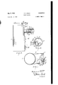
- Fig. 1 is a side elevational view of a furnace, mainly shown conventionally with the draft control of the invention installed in the flue thereof.
- Fig. 2 is a front elevational View of the control with portions broken away.
- Fig. 3 a view generally in vertical section on the line 33 of Fig. 2, the gate being shown in closed position in full lines and in open position in dotted lines.
- Fig. 4 is a fragmentary view showing a structural detail on the line 44 of Fig. 2.
- Fig. 5 is a view of another embodiment of the invention showing in side elevation a boile'r'and the draft control installed in the flue of the heatin equipment thereof.
- Fig. 6 is a front elevational view of the control of Fig. 5.
- Fig. '7 shows in section the flue of the furnace and in side elevation the housing and control applied to the flue.
- I designates the furnace, 2 the chimney and 3 the flue connectingthe furnace and chimney.
- the flue is provided with a laterally projecting housing 4 opening thereto.
- An annular F igate frame 5 is fitted in the outer end of the housing and is provided with an outwardly projecting flange G which serves as locating and reinforcing means for the gate frame.
- This frame is desirably formed of a sheet metal stamping.
- the gate frame 5 is provided at its inner end with a radially inwardly projecting flange I having on the opposite sides thereof the segmental portions 8 provided at their inner edges with wings 9 projecting inwardly of the housing.
- These wings are disposed in spaced parallel relation to swingably receive the gate'or damper 10 between them, the wings serve to substantially reduce or minimize passage of air around the sides of the gate, thus providing a much more uniform control or regulation than would be possible without the same.
- the gate iii is provided with a pintle or pivot rod ll arranged substantially below the center of the gate.
- the wings 9 are provided with bearing openings I2 of substantial size, as shown in Fig. 4, so that the pintle may have rolling contact with the lower edge thereof.
- the pintle H is attached to the rear side of the gate by means of the plate l3 secured by rivets I4 to the gate.
- the gate is weighted for barometric draft-control as follows: A threaded counterweight arm l5 projects through the offset 16 of the gate so that the arm is in the desired angular relation to the gate. A balancing weight I1 is threadedly 5'filconnected to the inner end of the arm, and a weight i8 is threadedly connected to the outer. end of the arm. The weight I8 is adjustable on the arm to provide suitable barometric control, as is old in the art.
- a control spring designated generally by the numeral l9 and comprising a coiled portion 20 terminating at one end in a tendency of any rocking motion of the loops about the bolt 25.
- the opposite end of the coiled portion 20 terminates in a rearwardly and upwardly projecting arm 26 terminating in a loop 21 normally engaging the gate to press the same inwardly into open position as shown by dotted lines in Fig. 3.
- a cable or chain 29 To a loop 28 intermediate the ends of the arm 26 is connected a cable or chain 29 by means of which the arm 26 may be raised so that the loop 21 no longer engages the gate to hold the same in open position.
- FIG. 3 shows in full lines, the arm 26 raised from engagement with the gate and out of the path of movement thereof, thereby permitting the same to freely swing against the force of the weight of the counterbalancing mechanism, for barometric draft control.
- and 26 are disposed in crossing relation, as shown in Fig. 3. It will be noted by reference Fig. 2 that the end portion of the arm 26 to which the cable is connected is offset laterally so as to be substantially in the same vertical plane with end coil opposit that from which the arm projects. This tends to prevent any distortion of the coiled portion when the cable is pulled upwardly.
- the arm 26 swings about the axis of the coil 20.
- the cable 29 When it is desired to check or bank the furnace fire the cable 29 is released. This permits the loop 21 of the control spring to engage gate and open the same into the dotted line position shown in Fig. 3. When there is need for heat the cable is pulled upwardly which releases the control spring from engagement of the gate as shown in full lines Fig. 3 which permits the gate to close under the force of the weight of the counterbalancing mechanism and to be thereafter automatically controlled by variations of pressure on the opposite sides of the gate.
- the cable may be operated by any suitable means either manual or automatic not shown. If the cable should break the control spring automatically opens the damper to check the fire. In other words the mechanism is such that it fails safe.
- a control lever designated generally by the numeral 30 is formed of a wire or rod circular in cross section and bent to provide a gate engaging arm 3
- the shaft portion is pivotally mounted in a bracket 34 secured by screws 35 to the gate frame as shown in Figs. 6 and '7. This permits the bracket and control lever to be connected to the gate frame when installed.
- the arm 32 is provided with a loop 36 to which is pivotally connected the weight 31.
- a cable or chain 38 engaging in loop 36 connects the arm 32 to a hook 39 on the end of lever 40.
- connects the hook 39 to the ash pit draft damper 42.
- the construction of the embodiment of Figs. 5, 6 and '7 is otherwise similar to that of the embodiment of Figs. 1 to 4.
- the lever 40 When it is desired to check or bank the fire of the boiler, the lever 40 is operated to lower the cable 38. This permits the weight 3,1,to pull down on the arm 32 of the lever 30 and thereby force the arm 3
- the lever 40 When there is need for heat the lever 40 is operated to pull the cable 38 upwardly. This raises the weight 31 and operates the lever 30 into such position that arm 3
- the cables 38 and ll being connected to the lever 43 and to the control lever 30 and ash pit draft damper 42 as shown and described, when the lever 40 is operated so as to open the gate or damper l0 then the ash pit draft damper 42 is simultaneously closed so as to check the fire, and when the lever 40 is operated to permit closing of the damper It) then the damper 42 is simultaneously opened so as to provide more heat. Should the cable 38 break, the control lever 30 under the influence of the weight 31 operates to open the damper l0 and thereby check the fire, the mechanism thus being such that it fails safe.
- the lever 40 obviously may be operated either manually or automatically by any suitable means, not shown.
- a draft control a housing, a gate frame disposed within said housing and defining a gate opening, a gate pivotally connected to said frame and disposed in said opening, a weight on said gate disposed to close the same for barometric draft control, means for opening the gate and holding the same in open position against the return action of its weight, said means including a coiled spring terminating at each end in a projecting arm, one arm being fixedly connected to said gate frame, the other arm being disposed to yieldingly press against the gate to open the gate and hold the same open against the return action of its weight, and a cable connected to said last named arm and disposed to pull the same away from the gate against the stress of said spring to permit the gate to close under the influence of its weight for barometric draft control.
- a draft control a housing, a gate frame disposed within said housing and defining a gate opening, a gate pivotally connected to said frame and disposed in said opening, a weight on said gate disposed to close the same for barometric draft control, means for opening the gate and holding the same in open position against the return action of its weight, said means including a coiled spring terminating at each end in a projecting arm, one arm being fixedly connected to said gate frame, the other arm being disposed to yieldingly press against the gate to open the gate and hold the same open against the return action of its weight and having the outer end portion thereof disposed in substantially the same vertical plane with the first mentioned arm, and a cable connected to said other arm and disposed to pull the same away from the gate against the stress of said spring to permit the gate to close under the infiluence of its weight for barometric draft con- 3.
- a housing a gate frame disposed within said housing and defining a gate opening, a gate pivotally connected to said frame and disposed in said opening, a weight on said gate disposed to close the same for barometric draft control, means for opening the gate and holding the same in open position against the return action of its weight, said means including a coiled spring terminating at each end in a projecting arm, one arm being fixedly connected to said gate frame, the other arm being disposed to yieldingly press against the gate to open the gate and hold the same open against the return action of its weight, and means connected to said last named arm and disposed to move the same away from the gate against the stress of said spring to permit the gate to close under the influence of its weight for barometric draft control.
- a housing defining a gate opening, a pivoted gate disposed in said opening, a weight on said gate disposed to close the same for barometric draft control, means for holding the gate open against the return action. of its weight, said means including a spring having one end fixedly associated relative to said housing and its other end disposed to yieldingly urge said gate to an open position and hold the same open against the return action of its weight, and a cable connected to said last named arm and disposed to pull the same against the stress of the spring to render the spring inoperative in holding the gate in open position and to permit the gate to close under the influence of its Weight for barometric draft control.
- a housing definin a gate opening, a pivoted gate disposed in said opening, a weight on said gate disposed to close the same for barometric draft control, means for holding the gate open against the return action of its weight, said means including a coiled spring having one end fixedly associated relative to said housing and its other end constituting an arm springable about the axis of the coil and disposed to yieldingly urge said gate to an open position and hold the same open against the return action of its weight, and mean connected to said arm and disposed to move the same against the stress of the spring to render the spring inoperative in holding the gate in open position and to permit the gate to close under the influence of its Weight for barometric draft control.
- a housing defining a gate opening, a pivoted gate disposed in said opening, means for urging said gate toward a closed position for barometric draft control, resilient means disposed to open said gate and hold the same open against the return action of said first mentioned means, said resilient means including a coiled spring having two arms projecting therefrom, one arm being attached to the housing for supporting the coil and the other arm being disposed to engage the gate and hold the same open, and means connected to the last named arm for rendering the same inoperative in holding the gate open, to thereby permit the gate to close under the return action of the first mentioned means for barometric draft control, said arms being disposed in crossing relation to each other when the gate is closed.
- a housing defining a gate opening, a pivoted gate disposed in said opening, a weight on said gate disposed to urge the gate toward a closed position for barometric draft control, a first means disposed to open said gate and hold the gate open against the return action of its weight, and a second means connected to said first means and operable against the orce of the first means for rendering said first means inoperative in holding the gate open to thereby permit the gate to close under the influence of its weight for barometric draft control, said first means being supportingly connected to the housing at one side thereof adjacent an end of the pivotal axis of the gate, and including an arm disposed to swing towards and from the gate and to engage the gate in radially spaced relation from the axis of the gate to open the same, said arm and gate projecting from their axes of swinging movement in substantially the same general direction to facilitate the arm swinging in substantially general parallelism to the gate during substantially the entire opening movement of the gate, said first means including means tending to urge said arm
- a housing defining a gate opening, a pivoted gate disposed in said opening, a first means connected to said gate for urging the same towards a closed position-for barometric draft control, a second means disposed to open said gate and hold the same open against the return action of said first means and a third means connected to said second means operable against the force of the second means to render the second means inoperative in holding the gate open to thereby permit the gate to close under the return action of said first means for barometric draft control, said second means being supportingly connected to the housing at one side thereof adjacent an end of the pivotal axis of the gate and including an arm disposed to swing toward and from the gates and to engage the gate in radially spaced relation from the pivotal axis of the gate to open the same, said arm and gate projecting from their axes of swinging movement in substantially the same general direction to facilitate the arm swinging in substantially general parallelism to th gate during substantially the entire opening movement thereof, said second means including means tending to urge said arm in
- a draft control a housing, a gate frame disposed in said housing and defining a gate opening, a pivoted gate disposed in said opening and weighted to urge said gate toward a closed position for barometric draft control, means for opening said gate and holding the same open against the return action of its weight, said means including a lever formed of a rod bent to provide a first arm, a second arm and a shaft portion intermediate said arms, a bearing on said gate frame for said shaft portion, said first arm being disposed to move the gate to an open position, a weight mount-ed on said second arm, said Weight and second arm being disposed to move said first arm to open the gate and hold the same open against the return action of the weight on the gate, and a cable connected to said control lever for moving the same against the influence of the Weight supported by the control lever to render the control lever inoperative in holding the gate in open position and to permit the gate to close under influence of its own weight for barometric draft control, said lever being supportingly connected to the housing at one side thereof adjacent an end of
- said lever being supportingly'connected to the'houslng at one side thereof adjacent an-end of the pivotal axis of the gate and including'an arm disposed to swing towards and from the gate and to engage the gate in radially spaced relation from the pivotal axis of the gate to open the same, said arm and gate projecting from their axes of swinging movement in substantially the same general direction to facilitate the arm swinging in substantially general parallelism to :thevgate during substantially the entire opening movement thereof, said arm and weight being disposed relative .to said lever to urge said arm towards the gate. at all times.
Description
E. A. F lELD Jan. 6, 1953 2,624,513
DRAFT CONTROL Filed Dec. 17 1949 2 SHEETS-SHEET l a w i ,O O 70 5 4 i I a Q i I I I 'E 75 a i i z IN VEN TOR. zI/l/d/"d 4. f/e/d ATTORA/EZ.
Jan. 6, 1953 E. A. FIELD DRAFT CONTROL Filed Dec. 17, 1949 2 SHEETS Ida/45a A -SHEET 2 JNVENTOR. 776/4 ATTORNEY.
Patented Jan. 6, 1953 UNITED STATES PATENT OFFICE DRAFT CQNTROL Edward A. Field, Mendota, 111.
Application December 17, 1949, Serial No. 133,575
Claims.
This invention relates to improvements in draft controls.
The main objects of the invention are:
First, to provide an improved barometric draft control having provision for opening the gate or damper of such a ccntrol and holding the same open, to thereby render the barometric control inoperative and check the fire in a furnace, to the flue of which the control is applied.
Second, to provide a draft control of the character above described in which the means for opening the gate or damper and holding the same open is normally operative to prevent normal barometric control of the gate or damper, and in which such means may be either manually or automatically operated to render the same inoperative in holding the gate open, to thereby permit normal barometric control of the gate.
Third, to provide a draft control which may be very economically produced and may be readily installed, and one in which the parts are so arranged that the gate and its supports cannot be injured in the event of excessive force being applied to the control, and one in which on failure of such control the gate is automatically opened to check the fire of the furnace.
Objects relating to details and economies of the invention will appear from the description to follow. The invention is pointed out and defined in the claims.
Preferred embodiments of the invention are illustrated in the accompanying drawings, in which:
Fig. 1 is a side elevational view of a furnace, mainly shown conventionally with the draft control of the invention installed in the flue thereof.
Fig. 2 is a front elevational View of the control with portions broken away.
Fig. 3 a view generally in vertical section on the line 33 of Fig. 2, the gate being shown in closed position in full lines and in open position in dotted lines.
Fig. 4 is a fragmentary view showing a structural detail on the line 44 of Fig. 2.
Fig. 5 is a view of another embodiment of the invention showing in side elevation a boile'r'and the draft control installed in the flue of the heatin equipment thereof.
Fig. 6 is a front elevational view of the control of Fig. 5. v
Fig. '7 shows in section the flue of the furnace and in side elevation the housing and control applied to the flue.
Referring to the accompanying drawing and the embodiment of the invention shown in Figs.
1 to 4, I designates the furnace, 2 the chimney and 3 the flue connectingthe furnace and chimney. The flue is provided with a laterally projecting housing 4 opening thereto. An annular F igate frame 5 is fitted in the outer end of the housing and is provided with an outwardly projecting flange G which serves as locating and reinforcing means for the gate frame. This frame is desirably formed of a sheet metal stamping.
101 The gate frame 5 is provided at its inner end with a radially inwardly projecting flange I having on the opposite sides thereof the segmental portions 8 provided at their inner edges with wings 9 projecting inwardly of the housing.
These wings are disposed in spaced parallel relation to swingably receive the gate'or damper 10 between them, the wings serve to substantially reduce or minimize passage of air around the sides of the gate, thus providing a much more uniform control or regulation than would be possible without the same.
The gate iii is provided with a pintle or pivot rod ll arranged substantially below the center of the gate. The wings 9 are provided with bearing openings I2 of substantial size, as shown in Fig. 4, so that the pintle may have rolling contact with the lower edge thereof. The pintle H is attached to the rear side of the gate by means of the plate l3 secured by rivets I4 to the gate.
0": The gate is weighted for barometric draft-control as follows: A threaded counterweight arm l5 projects through the offset 16 of the gate so that the arm is in the desired angular relation to the gate. A balancing weight I1 is threadedly 5'filconnected to the inner end of the arm, and a weight i8 is threadedly connected to the outer. end of the arm. The weight I8 is adjustable on the arm to provide suitable barometric control, as is old in the art.
In operating a furnace, there are certain conditions when it is desirable to prevent or elimi--v nate barometric control of the gate, for example, when it is desired to bank or check the fire in the furnace to which the control is applied.
*To this end I provide a control spring designated generally by the numeral l9 and comprising a coiled portion 20 terminating at one end in a tendency of any rocking motion of the loops about the bolt 25. The opposite end of the coiled portion 20 terminates in a rearwardly and upwardly projecting arm 26 terminating in a loop 21 normally engaging the gate to press the same inwardly into open position as shown by dotted lines in Fig. 3. To a loop 28 intermediate the ends of the arm 26 is connected a cable or chain 29 by means of which the arm 26 may be raised so that the loop 21 no longer engages the gate to hold the same in open position. Fig. 3 shows in full lines, the arm 26 raised from engagement with the gate and out of the path of movement thereof, thereby permitting the same to freely swing against the force of the weight of the counterbalancing mechanism, for barometric draft control. The arms 2| and 26 are disposed in crossing relation, as shown in Fig. 3. It will be noted by reference Fig. 2 that the end portion of the arm 26 to which the cable is connected is offset laterally so as to be substantially in the same vertical plane with end coil opposit that from which the arm projects. This tends to prevent any distortion of the coiled portion when the cable is pulled upwardly. The arm 26 swings about the axis of the coil 20. This arm and the gate l both extending upwardly that is in substantially the same general direction from their axes of swinging movements, as shown in Figs. 2 and 3, facilitates the arm swinging in substantially general parallelism to the gate during substantially the entire opening movement of the gate, and facilitates opening the gate to a widely opened substantially horizontal position as shown in dotted outline in Fig. 3.
When it is desired to check or bank the furnace fire the cable 29 is released. This permits the loop 21 of the control spring to engage gate and open the same into the dotted line position shown in Fig. 3. When there is need for heat the cable is pulled upwardly which releases the control spring from engagement of the gate as shown in full lines Fig. 3 which permits the gate to close under the force of the weight of the counterbalancing mechanism and to be thereafter automatically controlled by variations of pressure on the opposite sides of the gate. The cable may be operated by any suitable means either manual or automatic not shown. If the cable should break the control spring automatically opens the damper to check the fire. In other words the mechanism is such that it fails safe.
Referring to the embodiment of the invention shown in Figs. 5, 6 and '7, a control lever designated generally by the numeral 30 is formed of a wire or rod circular in cross section and bent to provide a gate engaging arm 3|, a weight supporting arm 32 and a shaft portion 33 intermediate the arms. The shaft portion is pivotally mounted in a bracket 34 secured by screws 35 to the gate frame as shown in Figs. 6 and '7. This permits the bracket and control lever to be connected to the gate frame when installed. The arm 32 is provided with a loop 36 to which is pivotally connected the weight 31. A cable or chain 38 engaging in loop 36 connects the arm 32 to a hook 39 on the end of lever 40. Another cable 4| connects the hook 39 to the ash pit draft damper 42. The construction of the embodiment of Figs. 5, 6 and '7 is otherwise similar to that of the embodiment of Figs. 1 to 4.
When it is desired to check or bank the fire of the boiler, the lever 40 is operated to lower the cable 38. This permits the weight 3,1,to pull down on the arm 32 of the lever 30 and thereby force the arm 3| into engagement with the gate and open the same against the force of weight l8 of the gate into the position shown in dotted lines in Fig. '7. When there is need for heat the lever 40 is operated to pull the cable 38 upwardly. This raises the weight 31 and operates the lever 30 into such position that arm 3| is vertically disposed and out of engagement with the gate, which permits the gate to close under the influence of its weight and thereby be automatically controlled by variations in pressure on the opposite sides thereof. The cables 38 and ll being connected to the lever 43 and to the control lever 30 and ash pit draft damper 42 as shown and described, when the lever 40 is operated so as to open the gate or damper l0 then the ash pit draft damper 42 is simultaneously closed so as to check the fire, and when the lever 40 is operated to permit closing of the damper It) then the damper 42 is simultaneously opened so as to provide more heat. Should the cable 38 break, the control lever 30 under the influence of the weight 31 operates to open the damper l0 and thereby check the fire, the mechanism thus being such that it fails safe. The lever 40 obviously may be operated either manually or automatically by any suitable means, not shown.
I have illustrated and described highly practical embodiments of the invention. I have not attempted to illustrate or describe other embodiments or adaptations as it is believed this disclosure will enable those skilled in the art to embody or adapt the invention as may be desired.
Having thus described my invention, what I claim as new and desire to secure by Letters Patent is:
1. In a draft control, a housing, a gate frame disposed within said housing and defining a gate opening, a gate pivotally connected to said frame and disposed in said opening, a weight on said gate disposed to close the same for barometric draft control, means for opening the gate and holding the same in open position against the return action of its weight, said means including a coiled spring terminating at each end in a projecting arm, one arm being fixedly connected to said gate frame, the other arm being disposed to yieldingly press against the gate to open the gate and hold the same open against the return action of its weight, and a cable connected to said last named arm and disposed to pull the same away from the gate against the stress of said spring to permit the gate to close under the influence of its weight for barometric draft control.
2. In a draft control, a housing, a gate frame disposed within said housing and defining a gate opening, a gate pivotally connected to said frame and disposed in said opening, a weight on said gate disposed to close the same for barometric draft control, means for opening the gate and holding the same in open position against the return action of its weight, said means including a coiled spring terminating at each end in a projecting arm, one arm being fixedly connected to said gate frame, the other arm being disposed to yieldingly press against the gate to open the gate and hold the same open against the return action of its weight and having the outer end portion thereof disposed in substantially the same vertical plane with the first mentioned arm, and a cable connected to said other arm and disposed to pull the same away from the gate against the stress of said spring to permit the gate to close under the infiluence of its weight for barometric draft con- 3. Ina draft control, a housing, a gate frame disposed within said housing and defining a gate opening, a gate pivotally connected to said frame and disposed in said opening, a weight on said gate disposed to close the same for barometric draft control, means for opening the gate and holding the same in open position against the return action of its weight, said means including a coiled spring terminating at each end in a projecting arm, one arm being fixedly connected to said gate frame, the other arm being disposed to yieldingly press against the gate to open the gate and hold the same open against the return action of its weight, and means connected to said last named arm and disposed to move the same away from the gate against the stress of said spring to permit the gate to close under the influence of its weight for barometric draft control.
4. In a draft control, a housing defining a gate opening, a pivoted gate disposed in said opening, a weight on said gate disposed to close the same for barometric draft control, means for holding the gate open against the return action. of its weight, said means including a spring having one end fixedly associated relative to said housing and its other end disposed to yieldingly urge said gate to an open position and hold the same open against the return action of its weight, and a cable connected to said last named arm and disposed to pull the same against the stress of the spring to render the spring inoperative in holding the gate in open position and to permit the gate to close under the influence of its Weight for barometric draft control.
5. In a draft control, a housing definin a gate opening, a pivoted gate disposed in said opening, a weight on said gate disposed to close the same for barometric draft control, means for holding the gate open against the return action of its weight, said means including a coiled spring having one end fixedly associated relative to said housing and its other end constituting an arm springable about the axis of the coil and disposed to yieldingly urge said gate to an open position and hold the same open against the return action of its weight, and mean connected to said arm and disposed to move the same against the stress of the spring to render the spring inoperative in holding the gate in open position and to permit the gate to close under the influence of its Weight for barometric draft control.
6. In a draft control, a housing defining a gate opening, a pivoted gate disposed in said opening, means for urging said gate toward a closed position for barometric draft control, resilient means disposed to open said gate and hold the same open against the return action of said first mentioned means, said resilient means including a coiled spring having two arms projecting therefrom, one arm being attached to the housing for supporting the coil and the other arm being disposed to engage the gate and hold the same open, and means connected to the last named arm for rendering the same inoperative in holding the gate open, to thereby permit the gate to close under the return action of the first mentioned means for barometric draft control, said arms being disposed in crossing relation to each other when the gate is closed.
'7. In a draft control, a housing defining a gate opening, a pivoted gate disposed in said opening, a weight on said gate disposed to urge the gate toward a closed position for barometric draft control, a first means disposed to open said gate and hold the gate open against the return action of its weight, and a second means connected to said first means and operable against the orce of the first means for rendering said first means inoperative in holding the gate open to thereby permit the gate to close under the influence of its weight for barometric draft control, said first means being supportingly connected to the housing at one side thereof adjacent an end of the pivotal axis of the gate, and including an arm disposed to swing towards and from the gate and to engage the gate in radially spaced relation from the axis of the gate to open the same, said arm and gate projecting from their axes of swinging movement in substantially the same general direction to facilitate the arm swinging in substantially general parallelism to the gate during substantially the entire opening movement of the gate, said first means including means tending to urge said arm inwardly towards the gate at all times, said second means in its entirety being a separate means from thefirst means.
8. In a draft control, a housing defining a gate opening, a pivoted gate disposed in said opening, a first means connected to said gate for urging the same towards a closed position-for barometric draft control, a second means disposed to open said gate and hold the same open against the return action of said first means and a third means connected to said second means operable against the force of the second means to render the second means inoperative in holding the gate open to thereby permit the gate to close under the return action of said first means for barometric draft control, said second means being supportingly connected to the housing at one side thereof adjacent an end of the pivotal axis of the gate and including an arm disposed to swing toward and from the gates and to engage the gate in radially spaced relation from the pivotal axis of the gate to open the same, said arm and gate projecting from their axes of swinging movement in substantially the same general direction to facilitate the arm swinging in substantially general parallelism to th gate during substantially the entire opening movement thereof, said second means including means tending to urge said arm inwardly towards the gate at all times, said third means in its entirety being a separate means from said second means.
9. In a draft control, a housing, a gate frame disposed in said housing and defining a gate opening, a pivoted gate disposed in said opening and weighted to urge said gate toward a closed position for barometric draft control, means for opening said gate and holding the same open against the return action of its weight, said means including a lever formed of a rod bent to provide a first arm, a second arm and a shaft portion intermediate said arms, a bearing on said gate frame for said shaft portion, said first arm being disposed to move the gate to an open position, a weight mount-ed on said second arm, said Weight and second arm being disposed to move said first arm to open the gate and hold the same open against the return action of the weight on the gate, and a cable connected to said control lever for moving the same against the influence of the Weight supported by the control lever to render the control lever inoperative in holding the gate in open position and to permit the gate to close under influence of its own weight for barometric draft control, said lever being supportingly connected to the housing at one side thereof adjacent an end of 'the vpivotal axis of the gate, said'firstarm being disposed to swing -towards and from thegate and to engage the gate-in radially spaced relation from its 1 pivotal axis to open the same, said first arm andzgate projecting from their axes of 'swinging movement in substantially the samegeneral direction to'facilitate said first arm swinging in substantially generalzparallelism to thegate during-subcontrol, acontrol lever disposed for opening said gate and holding the same open against thereturn actionof the weight on the gate, a weight on said control lever disposed to turn the lever toopen -.the gate, the force of "the last named weight in turning the control leverbeing such thatthe-gate is opened and held open by the lever: against the closing action of the weight .on
the gate, and means connected to said control lever for turning the same againstthe force of the weight thereon to render the control lever inoperative in holding the gate open to permit Jthe=gate to close by the force of the weight-on the .gate for I barometric 7 draft control, said lever being supportingly'connected to the'houslng at one side thereof adjacent an-end of the pivotal axis of the gate and including'an arm disposed to swing towards and from the gate and to engage the gate in radially spaced relation from the pivotal axis of the gate to open the same, said arm and gate projecting from their axes of swinging movement in substantially the same general direction to facilitate the arm swinging in substantially general parallelism to :thevgate during substantially the entire opening movement thereof, said arm and weight being disposed relative .to said lever to urge said arm towards the gate. at all times.
EDWARD A. FIELD.
REFERENCES CITED The following references are of record-1n the file of this patent:
UNITED STATES PATENTS Number Name Date 840,520 Scharf Jan. 8, 1907 1,775,065 Brown Sept. 2, 1930 2,211,501 Goodhart Aug. 13, 1940 2,259,973 Firehammer Oct.21,'1941 2,269,932 Field Jan. 13, 1942 2,291,884 Den Besten et al.- i Aug. 4, 1942 2,417,571 Short Mar. 18, 1947 2,422,496 Morrow June-17, 1947 2,514,446 Field 1 -Ju1y-11, 1950
Priority Applications (1)
| Application Number | Priority Date | Filing Date | Title |
|---|---|---|---|
| US133575A US2624513A (en) | 1949-12-17 | 1949-12-17 | Draft control |
Applications Claiming Priority (1)
| Application Number | Priority Date | Filing Date | Title |
|---|---|---|---|
| US133575A US2624513A (en) | 1949-12-17 | 1949-12-17 | Draft control |
Publications (1)
| Publication Number | Publication Date |
|---|---|
| US2624513A true US2624513A (en) | 1953-01-06 |
Family
ID=22459284
Family Applications (1)
| Application Number | Title | Priority Date | Filing Date |
|---|---|---|---|
| US133575A Expired - Lifetime US2624513A (en) | 1949-12-17 | 1949-12-17 | Draft control |
Country Status (1)
| Country | Link |
|---|---|
| US (1) | US2624513A (en) |
Cited By (5)
| Publication number | Priority date | Publication date | Assignee | Title |
|---|---|---|---|---|
| US2825506A (en) * | 1953-05-11 | 1958-03-04 | William F Steinen | Draft regulator |
| US2840317A (en) * | 1953-06-24 | 1958-06-24 | Joseph P Kozak | Draft regulator |
| US2990118A (en) * | 1956-12-20 | 1961-06-27 | William F Steinen | Draft regulator construction |
| US3982560A (en) * | 1974-05-13 | 1976-09-28 | Fred Dibert | Ventilating apparatus for heat transfer systems |
| US5169498A (en) * | 1991-09-03 | 1992-12-08 | Kamyr, Inc. | Atmospheric pre-steaming chip bin vacuum and pressure relief device |
Citations (9)
| Publication number | Priority date | Publication date | Assignee | Title |
|---|---|---|---|---|
| US840520A (en) * | 1905-03-11 | 1907-01-08 | Gregory H Scharf | Draft-regulator for furnaces. |
| US1775065A (en) * | 1929-07-12 | 1930-09-02 | Herbert J Brown | Check damper |
| US2211501A (en) * | 1937-07-17 | 1940-08-13 | Charles I Goodhart | Furnace regulating system |
| US2259973A (en) * | 1939-10-09 | 1941-10-21 | Welton E Firehammer | Furnace control |
| US2269932A (en) * | 1939-07-28 | 1942-01-13 | Jr Edward A Field | Draft control |
| US2291884A (en) * | 1938-07-02 | 1942-08-04 | Besten Gilbert Den | Draft regulating device |
| US2417571A (en) * | 1944-08-07 | 1947-03-18 | Hotstream Heater Co | Draft control mechanism |
| US2422496A (en) * | 1945-01-04 | 1947-06-17 | Hotstream Heater Co | Control device for draft regulators |
| US2514446A (en) * | 1947-02-28 | 1950-07-11 | Jr Edward A Field | Draft limiting damper |
-
1949
- 1949-12-17 US US133575A patent/US2624513A/en not_active Expired - Lifetime
Patent Citations (9)
| Publication number | Priority date | Publication date | Assignee | Title |
|---|---|---|---|---|
| US840520A (en) * | 1905-03-11 | 1907-01-08 | Gregory H Scharf | Draft-regulator for furnaces. |
| US1775065A (en) * | 1929-07-12 | 1930-09-02 | Herbert J Brown | Check damper |
| US2211501A (en) * | 1937-07-17 | 1940-08-13 | Charles I Goodhart | Furnace regulating system |
| US2291884A (en) * | 1938-07-02 | 1942-08-04 | Besten Gilbert Den | Draft regulating device |
| US2269932A (en) * | 1939-07-28 | 1942-01-13 | Jr Edward A Field | Draft control |
| US2259973A (en) * | 1939-10-09 | 1941-10-21 | Welton E Firehammer | Furnace control |
| US2417571A (en) * | 1944-08-07 | 1947-03-18 | Hotstream Heater Co | Draft control mechanism |
| US2422496A (en) * | 1945-01-04 | 1947-06-17 | Hotstream Heater Co | Control device for draft regulators |
| US2514446A (en) * | 1947-02-28 | 1950-07-11 | Jr Edward A Field | Draft limiting damper |
Cited By (5)
| Publication number | Priority date | Publication date | Assignee | Title |
|---|---|---|---|---|
| US2825506A (en) * | 1953-05-11 | 1958-03-04 | William F Steinen | Draft regulator |
| US2840317A (en) * | 1953-06-24 | 1958-06-24 | Joseph P Kozak | Draft regulator |
| US2990118A (en) * | 1956-12-20 | 1961-06-27 | William F Steinen | Draft regulator construction |
| US3982560A (en) * | 1974-05-13 | 1976-09-28 | Fred Dibert | Ventilating apparatus for heat transfer systems |
| US5169498A (en) * | 1991-09-03 | 1992-12-08 | Kamyr, Inc. | Atmospheric pre-steaming chip bin vacuum and pressure relief device |
Similar Documents
| Publication | Publication Date | Title |
|---|---|---|
| US2299833A (en) | Louver mechanism for attic ventilation | |
| US2624513A (en) | Draft control | |
| US2259973A (en) | Furnace control | |
| US2388253A (en) | Barometric draft control | |
| US2652200A (en) | Barometric draft regulator | |
| US2514446A (en) | Draft limiting damper | |
| US2101315A (en) | Automatic check damper | |
| US2793580A (en) | Ventilating device | |
| US2234259A (en) | Door construction | |
| US2650029A (en) | Barometric draft regulator | |
| US2126994A (en) | Automatic draft controller | |
| US1594219A (en) | Oven-door-operating mechanism | |
| US1830036A (en) | Draft regulator | |
| US2484674A (en) | Garage door | |
| US2724857A (en) | Control arm and counterbalance for overhead door | |
| US2291018A (en) | Draft regulator | |
| US2253290A (en) | Draft control | |
| GB683922A (en) | A new or improved apparatus for controlling the draught produced by the chimneys or flues of furnaces, boilers, stoves or kilns | |
| US1574711A (en) | Automatic draft control | |
| US2056410A (en) | Damper | |
| US2974751A (en) | Door clutch mechanism | |
| US1079824A (en) | Automatic furnace-damper. | |
| US1975214A (en) | Flushing device | |
| US2278927A (en) | Thermostatic controlling device for furnaces | |
| US2652584A (en) | Garage door supporting hardware |