US2575201A - Curved track overhead door - Google Patents
Curved track overhead door Download PDFInfo
- Publication number
- US2575201A US2575201A US639854A US63985446A US2575201A US 2575201 A US2575201 A US 2575201A US 639854 A US639854 A US 639854A US 63985446 A US63985446 A US 63985446A US 2575201 A US2575201 A US 2575201A
- Authority
- US
- United States
- Prior art keywords
- door
- panel
- tracks
- trolleys
- track
- Prior art date
- Legal status (The legal status is an assumption and is not a legal conclusion. Google has not performed a legal analysis and makes no representation as to the accuracy of the status listed.)
- Expired - Lifetime
Links
- 238000010276 construction Methods 0.000 description 9
- 239000000725 suspension Substances 0.000 description 6
- 238000013459 approach Methods 0.000 description 2
- 230000004048 modification Effects 0.000 description 1
- 238000012986 modification Methods 0.000 description 1
Images


Classifications
-
- E—FIXED CONSTRUCTIONS
- E05—LOCKS; KEYS; WINDOW OR DOOR FITTINGS; SAFES
- E05D—HINGES OR SUSPENSION DEVICES FOR DOORS, WINDOWS OR WINGS
- E05D15/00—Suspension arrangements for wings
- E05D15/40—Suspension arrangements for wings supported on arms movable in vertical planes
- E05D15/406—Suspension arrangements for wings supported on arms movable in vertical planes with pivoted arms and sliding guides
- E05D15/408—Suspension arrangements for wings supported on arms movable in vertical planes with pivoted arms and sliding guides with sliding guides fixed to the wing
-
- E—FIXED CONSTRUCTIONS
- E05—LOCKS; KEYS; WINDOW OR DOOR FITTINGS; SAFES
- E05D—HINGES OR SUSPENSION DEVICES FOR DOORS, WINDOWS OR WINGS
- E05D15/00—Suspension arrangements for wings
- E05D15/36—Suspension arrangements for wings moving along slide-ways so arranged that one guide-member of the wing moves in a direction substantially perpendicular to the movement of another guide member
- E05D15/38—Suspension arrangements for wings moving along slide-ways so arranged that one guide-member of the wing moves in a direction substantially perpendicular to the movement of another guide member for upwardly-moving wings, e.g. up-and-over doors
-
- E—FIXED CONSTRUCTIONS
- E05—LOCKS; KEYS; WINDOW OR DOOR FITTINGS; SAFES
- E05Y—INDEXING SCHEME ASSOCIATED WITH SUBCLASSES E05D AND E05F, RELATING TO CONSTRUCTION ELEMENTS, ELECTRIC CONTROL, POWER SUPPLY, POWER SIGNAL OR TRANSMISSION, USER INTERFACES, MOUNTING OR COUPLING, DETAILS, ACCESSORIES, AUXILIARY OPERATIONS NOT OTHERWISE PROVIDED FOR, APPLICATION THEREOF
- E05Y2900/00—Application of doors, windows, wings or fittings thereof
- E05Y2900/10—Application of doors, windows, wings or fittings thereof for buildings or parts thereof
- E05Y2900/13—Type of wing
- E05Y2900/132—Doors
Definitions
- Doors of great width are necessary in certain types of industrial buildings, 'for example, airplane hangars, in which it is necessary to pro ⁇ v vide a wide span free from obstructions to permit the entry and exit of aircraft having 'a long Wing spread.
- Many lof these doors are of the tilting-lift type, i. e., they are supported adjacent their upper corners by trolleys secured near the upper edge and travel-ing on' substantially horizontal tracks. Additional' trolleys pi'vted to the sides of the door on a horizontal axis parallel to the bottom edge of the door and spaced theres above, travel on tracks curving upwardly and.
- I provide suspension members see cured at their ends to the door panel adjacent the upper and lower edges thereof, and traveling,
- the suspension members may be in the form effarigid curved track or a flexible cable and, in either case, serve to support the door panel 'in'- tei-mediate its side -edges and yavc'nid v excessive deflection'thereof.
- Figure 1 is a diagrammatic. elevation of a building having a door embodying. the invention, the,
- Figure 2 ⁇ is a partial section taken .along the plane of line AII--fII of Figure 1; .Y
- Figure-3 is asimilar sectiontaken along theplane of yline III-#II'I-.jof Figure 1, parts beyond the plane'of section being omitted;
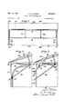
- Figure 4 is a section similar to Figure 3 shows ing parts beyond the vplane of section, the door being in closed position;
- Figure 5 va vview similar .to Figure .4 showing the door in open position;
- Figure .6 is a .diagrammatic perspective view showing a modied construction with the door closed; and v Figure 7 is a similar View showing the door Open;
- a building I0 for example, an .airplane hangar
- a :roof covering I4 is carried .by purlins I5 extending across the trusses ..I3.
- a tilting-lift door panel I8 is adaptaV ed to close the open side of the building.
- the panel I8 Vhas trolleys vI.9 ⁇ secured thereto adjacent ⁇ the ⁇ upper" corners.
- the curvature of the tracks 25 is such that the rollers 25 will carry a lportion of the weight of the panel at all points in its upward tilting movement to open position. That is to say, the curvature of the beams is dened by the locus of the axis of rollers 26, if the ldoor were held stationary and the building revolved relative thereto.
- Cables 21 secured to the upper edge of the door panel are taken up by motor-driven winches 28 when it is desired to open the door.
- the Winches may conveniently be carried by the roof trusses I3.
- the upperv edge or head of the door panel is drawn inwardly from the position shown in Figure 4 to the lintermediate position shown in Figures, l through 3 and, finally, to the fully open position shown in Figure 5.
- rollers 26 support a portionof the weight of the panel I8, thus reducing the span between points of support from the distance between the tracks 20 to the distance between them and the suspension means or beams 24. This materiallyreduces the deflection of the. panel between supports and permits a much lighter construction to be employed than would otherwise be necessaryto keep the deflection below the permissible maximum.
- the support afforded by the rollers 26 is applied adjacent the lower edge of the panel.
- will support the upper edge of the panel in open position.
- the winches 28 may be disposed as shown in the drawings so thatwhen the door is open, the vcables 21 exert asubstantial vertical component. of force on the suspension means or beams 25, thus making it unnecessary to provide ⁇ the tracks 2l and trolleys cooperating therewith.
- FIG. 6 and '1 show a modified construction of. the door panel 30 adapted to close the open side of a building 3
- the panel has cables 32 secured adjacent the lower edge thereof at points spaced across its width.- The cables are trained around sheaves 33 journaled inside the building adjacent openings 34 through which the cables extend. The other ends of the cables are secured to the upper edge of the panel as at 35. Rollers 31 at the upper corners of the panel travel in horizontal tracks 38.
- the invention is characterized by important advantages over tilting-lift doors as previously constructed, particularly in the case of doors having va large span, such as those required for airplane hangars.
- the intermediate supports are effective at the upper edge of the door in the beginning of f the tilting movement of thefpanel but remain xed as the panel continues to move and approach the lower edge as the panel moves into substantially horizontal position in which the deflection thereof between supports under its own weight is a maximum.
- the invention is simple and inexpensive, the acl,- ditional parts and structural members required being simply the suspending beams or cables with their supporting rollers or sheaves.
- the door may be made lighter and less rigid than heretofore since the possible deflection of the panel when in horizontal position is greatly reduced by the intermediate suspension means.
- a tilting-door assembly for wide panel doors or the like supported in a structure and adapted to be in generally vertical position when closedand to be tiltable inwardly and upwardly into generally Vhorizontal position when opened to providea clear opening, Vin combination, inter-i engagingqmeans,respectively connected to the door adjacent the upper edge thereof and to theV structure Vfor guidably supporting said door inwardly upon being opened, a rigid curved track fixed on the outside of said door and bowing outwardly intermediate the sides thereof and spaced laterally relative said interengaging means, said curved track lying in a substantially vertical plane,.a depending, laterally projecting member connected to said structure and supportably engaging 'said track, the engagement of said track and projecting member and said interengaging meansA dening the position of said door, and means connected to said door adjacent the upper portion thereof to move said ⁇ upper portion inwardly upon the opening of saidl door, whereby wide panel doors or the like receive laterally intermediate support during the opening and closingY thereof without requiring any obstruction in the doorway.
- interengaging means respectively connected to the door adjacent the upper edge thereof and to the structure for guidably supporting said door inwardly upon being opened, a rigid bow-shaped track fixed on the outside of said door intermediate the sides thereof and spaced from said interengaging means, said bow-shaped track lying in a substantially vertical plane and bowing outwardly and downwardly, said bow-shaped track further having the channel thereof facing one of the sides of said door, a relatively fixed hookshaped member connected to said structure and supportedly engaging said channel of said bowshaped track, the engagement of said bowshaped track and hook-shaped member and said interengaging means defining the position of said door, and means connected to said door inwardly of and above said door to move the upper portion of said door inwardly upon the opening thereof, whereby wide panel doors or the like receive laterally intermediate support during
- a tilting-lift door assembly for wide panel doors or the like supported in a structure and adapted to be in generally vertical position when closed and to be tiltable inwardly and upwardly into generally horizontal position when opened to provide a clear opening
- spaced trolleys respectively connected to the door adjacent the upper edge thereof, generally horizontal tracks for said trolleys connected to the structure adjacent the upper edges of said doors and adapted to engage said trolleys to guide the upper portion of said door
- a rigid bow-shaped and laterally channeled track fixed on the outside of said door intermediate the sides thereof and spaced from said trolleys, said bow-shaped track lying in a substantially vertical plane
- a relatively fixed trolley depending from said structure and supportably engaging the channel in said bowshaped track
- said tracks and said trolleys respectively dening the position of said door
- a tilting-lift door assembly for wide panel doors or the like supported in a structure and adapted to be in generally vertical position when closed and to be tiltable inwardly and upwardly into generally horizontal position when opened to provide a clear opening
- spaced trolleys respectively connected to the door adjacent the upper edge thereof, generally horizontal tracks for said trolleys connected to the structure adjacent the upper edges of said doors and adapted to engage said trolleys to guide the upper portion of said door
- trolleys connected to said door adjacent the lower portions of the respective sides thereof, upwardly and inwardly curved tracks connected to said structure adjacent the respective sides of said door and adapted to engage said last-mentioned trolleys
- said respective tracks and trolleys defining the position of and guiding said door during the movements thereof, at least one rigid bow-shaped and laterally channeled track fixed on the outside of said door intermediate said respective first-mentioned tracks and trolleys, said rigid bow-shaped track lying in a substantially vertical plane, a xed trolley connected to said structure and supportably engaging the channel of said bow-shaped track in
Landscapes
- Engineering & Computer Science (AREA)
- Mechanical Engineering (AREA)
- Support Devices For Sliding Doors (AREA)
Description
Nov. 13, 1951 .1. E. TlLLoTsoN 2,575,201
cum/ED TRACK OVERHEAD nooR INVENTO R i NOV- 13, 1951 J. E. TlLLoTsoN 2,575,201
cuRvED TRACK OVERHEAD DooR Filed Jan. 8, 1946 l 3 Sheets-Sheet 2 INVENTOR dared/5 77//0f50/7 NOV- 13, 1951 J. E. TaLLoTsoN cuRvED TRACK OVERHEAD DooR 3 Sheets-Sheet 3 Filed Jan. 8, 1946 INVENTOR dared'. 777/0750/7 7 A? Patented Nov. 13, 1951 oonvno TRACK OVRHEAD DOOR V` Jared E. Tillot'son, Allison Pai-k, Pa., assigner to .Blaw-Knox Company," Pittsburgh, Pa., a corporation of New J ersey Application January s, 1946, serial Nq. c3a's54 l This invention relates to a tilting-lift door and, in particular, to a dooradapted for buildings Where a very Wide, unobstructed opening de@- sired. a
Doors of great width are necessary in certain types of industrial buildings, 'for example, airplane hangars, in which it is necessary to pro`v vide a wide span free from obstructions to permit the entry and exit of aircraft having 'a long Wing spread. Many lof these doors are of the tilting-lift type, i. e., they are supported adjacent their upper corners by trolleys secured near the upper edge and travel-ing on' substantially horizontal tracks. Additional' trolleys pi'vted to the sides of the door on a horizontal axis parallel to the bottom edge of the door and spaced theres above, travel on tracks curving upwardly and.
ection when disposed in a vertical plane and. supported at their ends, by reason of their cone siderable height. When tilted'to' open position, however, objectionable deection may occur un= less special precautions are taken in the design. Usually these result in a heavy massive con.; struction. While additional supporting rollers traveling on horizontal tracks .between the side edges of the door may be provided.. forA supporte' ing the upper edge, the lower. edge of the .door
is without support between the upwardly and in= wardly curving guide tracks `at the extreme sides of the opening in the building wall.
I have invented a novel .form of .tilting-liftk door provided with auxiliary Ysuspension meme.
bers for supporting the door paneliat points ine termediate the side edges thereof, wherebyex cessive deflection is avoided without `requiring the construction to be such as to increase. thev weight of the door as -a whole. Invarpreferre'd embodiment, I provide suspension members see cured at their ends to the door panel adjacent the upper and lower edges thereof, and traveling,
on fixed rollers. The portions of the 4suspension members intermediate their ends are spaced from the door panel on the external side thereof.v The suspension members may be in the form effarigid curved track or a flexible cable and, in either case, serve to support the door panel 'in'- tei-mediate its side -edges and yavc'nid v excessive deflection'thereof. i
'.5 claims.. (o1. L20-.19)
2 A. complete understanding 'of the inventi may be obtained from the following detailed .dee scription which refers to vthe accompanying' drawings illustrating a preferred embodiment and a modication. In the drawings,
Figure 1 is a diagrammatic. elevation of a building having a door embodying. the invention, the,
door being shown in partlyopen position;
:Figure 2` is a partial section taken .along the plane of line AII--fII of Figure 1; .Y
. Figure-3 is asimilar sectiontaken along theplane of yline III-#II'I-.jof Figure 1, parts beyond the plane'of section being omitted;
lFigure 4 is a section similar to Figure 3 shows ing parts beyond the vplane of section, the door being in closed position; Figure 5 va vview similar .to Figure .4 showing the door in open position;
Figure .6 isa .diagrammatic perspective view showing a modied construction with the door closed; and v Figure 7 is a similar View showing the door Open;
Referring now in detail to the drawingsv and, for the present to Figures 1 through 5', a building I0, for example, an .airplane hangar, `comprises structural columns' Ill, lintelbeam's I2 carried thereby and roof trusses .I3 .extending between the beams. A :roof covering I4 is carried .by purlins I5 extending across the trusses ..I3. The
ends I6 andone sidev I'I .of the building .may 'be' closed by any desired construction. The .other side of the building -is .open between corner columns I I. A tilting-lift door panel I8 is adaptaV ed to close the open side of the building.
The panel I8 Vhas trolleys vI.9`secured thereto adjacent `the` upper" corners. The trolleys :Il
travel on tracks 20 extending inwardly from `.the
My improvement in the meansforisupporting the panel I8 `czornprises one .orlmore suspension means 24, preferably vspaced inwardly freni-tile side edges ofthe panel. ln the form of .the in` vention illustrated in llguresI l through 5;;.each suspensionmeans comprises .a curved track 25' secured to the panel adjacent the upper and lower edges thereof but spaced from the panel at points between said edges. Specifically, the tracks 25 are curved beams bowed outwardly from the door panel on the external side thereof. The tracks 25 ride on xed trolleys 26 carried by the building frame. The curvature of the tracks 25 is such that the rollers 25 will carry a lportion of the weight of the panel at all points in its upward tilting movement to open position. That is to say, the curvature of the beams is dened by the locus of the axis of rollers 26, if the ldoor were held stationary and the building revolved relative thereto.
n.It will be appreciated that the rollers 26 support a portionof the weight of the panel I8, thus reducing the span between points of support from the distance between the tracks 20 to the distance between them and the suspension means or beams 24. This materiallyreduces the deflection of the. panel between supports and permits a much lighter construction to be employed than would otherwise be necessaryto keep the deflection below the permissible maximum. As the panel I8 approaches the fully open position of Figure .5, the support afforded by the rollers 26 is applied adjacent the lower edge of the panel. The trolleys like those shown at I9 cooperating with the intermediate horizontal tracks 2| will support the upper edge of the panel in open position. Instead of relying on tracks 2 l the winches 28 may be disposed as shown in the drawings so thatwhen the door is open, the vcables 21 exert asubstantial vertical component. of force on the suspension means or beams 25, thus making it unnecessary to provide `the tracks 2l and trolleys cooperating therewith. A
VWhen it is desired .to close the door, operation of the Winches 28 to pay out the cables 21 permitsthe panel to travel downwardly in the tracks 23vr and tilt back to vertical position as it descends. The beams 24 continue to support the panel intermediate the tracks 23 particularly in that portion of the travel of the panel before it reachesv substantially vertical position. It will be evident that the beams 24 may be provided with lattice members to constitute a truss, instead of using the simple bow-shaped beams illustrated in the y drawings.
Y Figures 6 and '1 show a modified construction of. the door panel 30 adapted to close the open side of a building 3|.A The panel has cables 32 secured adjacent the lower edge thereof at points spaced across its width.- The cables are trained around sheaves 33 journaled inside the building adjacent openings 34 through which the cables extend. The other ends of the cables are secured to the upper edge of the panel as at 35. Rollers 31 at the upper corners of the panel travel in horizontal tracks 38.
It will be apparent that when the upper edge of the door panel is drawn inwardly as by the cable and winch arrangement referred to above, the cables 32 will support the panel at the extreme side edges thereof and also at the intermediate positions occupied by the cables and sheaves. In other words, the construction of Figures 6 and '1 dispenses with the necessity for the trolleys 22 and the guide tracks 23 of the construction first described, yet supports the panel at intermediate points as well as the side edges thereby `materially reducing the span between points of support and likewise reducing the maximum deflection of the panel between supports.
It will be apparent from the foregoing that the invention is characterized by important advantages over tilting-lift doors as previously constructed, particularly in the case of doors having va large span, such as those required for airplane hangars. By means of the construction de- .,scribed, such doors are supported at points between the side edges thereof. The intermediate supports are effective at the upper edge of the door in the beginning of f the tilting movement of thefpanel but remain xed as the panel continues to move and approach the lower edge as the panel moves into substantially horizontal position in which the deflection thereof between supports under its own weight is a maximum. The invention is simple and inexpensive, the acl,- ditional parts and structural members required being simply the suspending beams or cables with their supporting rollers or sheaves. By virtue of these intermediate supports the door may be made lighter and less rigid than heretofore since the possible deflection of the panel when in horizontal position is greatly reduced by the intermediate suspension means.
Although I have illustrated and described but a preferred embodiment of the invention and a modification, it will be recognized that changes in the arrangement of the parts or details of construction may be made without departing from the spirit of the invention or the scope of the appended claims.
I claim: 1 p
1. In a tilting-door assembly for wide panel doors or the like supported in a structure and adapted to be in generally vertical position when closedand to be tiltable inwardly and upwardly into generally Vhorizontal position when opened to providea clear opening, Vin combination, inter-i engagingqmeans,respectively connected to the door adjacent the upper edge thereof and to theV structure Vfor guidably supporting said door inwardly upon being opened, a rigid curved track fixed on the outside of said door and bowing outwardly intermediate the sides thereof and spaced laterally relative said interengaging means, said curved track lying in a substantially vertical plane,.a depending, laterally projecting member connected to said structure and supportably engaging 'said track, the engagement of said track and projecting member and said interengaging meansA dening the position of said door, and means connected to said door adjacent the upper portion thereof to move said` upper portion inwardly upon the opening of saidl door, whereby wide panel doors or the like receive laterally intermediate support during the opening and closingY thereof without requiring any obstruction in the doorway. Y
v2.1In a tilting-lift door assembly for wide panel doors or the like supported in a structure and adapted to be in generally vertical position when closed and to be tiltable inwardly and upwardly into generally horizontal positionvwhen opened terengaging means respectively connected to the door respectively adjacent the upper and lower tojprovide a clearropening, in combination, in-- edges thereof and to the structure for guiding said door upon movement thereof, a rigid curved track fixed on the outside of said door and bowing outwardly intermediate the sides thereof and spaced laterally relative said interengaging means, said curved track lying in a substantially Vertical plane, a depending, laterally projecting member connected to said structure and supportably engaging said track, the engagement of said track and projecting member and said interengaging means dening the position of said door, and means connected to said door adjacent the upper portion thereof to move said upper portion inwardly upon the opening of said door, whereby wide panel doors or the like receive laterally intermediate support during the opening and closing thereof without requiring any obstruction in the doorway.
3. In a tilting-lift door assembly for wide panel doors or the like supported in a structure and adapted to be in generally vertical position when closed and to be tiltable inwardly and upwardly into generally horizontal position when opened to provide a clear opening, in combination, interengaging means respectively connected to the door adjacent the upper edge thereof and to the structure for guidably supporting said door inwardly upon being opened, a rigid bow-shaped track fixed on the outside of said door intermediate the sides thereof and spaced from said interengaging means, said bow-shaped track lying in a substantially vertical plane and bowing outwardly and downwardly, said bow-shaped track further having the channel thereof facing one of the sides of said door, a relatively fixed hookshaped member connected to said structure and supportedly engaging said channel of said bowshaped track, the engagement of said bowshaped track and hook-shaped member and said interengaging means defining the position of said door, and means connected to said door inwardly of and above said door to move the upper portion of said door inwardly upon the opening thereof, whereby wide panel doors or the like receive laterally intermediate support during the opening and closing thereof without requiring any obstruction in the doorway.
4. In a tilting-lift door assembly for wide panel doors or the like supported in a structure and adapted to be in generally vertical position when closed and to be tiltable inwardly and upwardly into generally horizontal position when opened to provide a clear opening, in combination, spaced trolleys respectively connected to the door adjacent the upper edge thereof, generally horizontal tracks for said trolleys connected to the structure adjacent the upper edges of said doors and adapted to engage said trolleys to guide the upper portion of said door, a rigid bow-shaped and laterally channeled track fixed on the outside of said door intermediate the sides thereof and spaced from said trolleys, said bow-shaped track lying in a substantially vertical plane, a relatively fixed trolley depending from said structure and supportably engaging the channel in said bowshaped track, said tracks and said trolleys respectively dening the position of said door, and means connected to said door inwardly thereof and adjacent the upper portion of said door to move said door at least upon the opening thereof, whereby wide panel doors or the like receive laterally intermediate support during the opening and closing thereof without requiring any obstruction in the doorway.
5. In a tilting-lift door assembly for wide panel doors or the like supported in a structure and adapted to be in generally vertical position when closed and to be tiltable inwardly and upwardly into generally horizontal position when opened to provide a clear opening, in combination, spaced trolleys respectively connected to the door adjacent the upper edge thereof, generally horizontal tracks for said trolleys connected to the structure adjacent the upper edges of said doors and adapted to engage said trolleys to guide the upper portion of said door, trolleys connected to said door adjacent the lower portions of the respective sides thereof, upwardly and inwardly curved tracks connected to said structure adjacent the respective sides of said door and adapted to engage said last-mentioned trolleys, said respective tracks and trolleys defining the position of and guiding said door during the movements thereof, at least one rigid bow-shaped and laterally channeled track fixed on the outside of said door intermediate said respective first-mentioned tracks and trolleys, said rigid bow-shaped track lying in a substantially vertical plane, a xed trolley connected to said structure and supportably engaging the channel of said bow-shaped track in substantially all of the positions of said door determined by said respective guiding tracks and trolleys, and means connected to said door inwardly and adjacent the upper portion thereof to move said door at least during the opening thereof, whereby wide panel doors or the like receive laterally intermediate support during the opening and closing thereof without requiring any obstruction in the doorway and a regulator roof may be provided on said structure.
J ARED E. TILLOTSON.
REFERENCES CITED The following references are of record in the le of this patent:
UNITED STATES PATENTS Number Name Date 965,940 Ritter Aug. 2, 1910 1,216,202 Boughton Feb. 13, 1917 2,151,845 Goodrich Mar. 28, 1939 FOREIGN PATENTS Number Country Date 57,548 Sweden of 1923 164,103 Switzerland of 1933 195,565 Great Britain of 1923 641,981 France of 1928 810,561 France of 1936
Priority Applications (1)
| Application Number | Priority Date | Filing Date | Title |
|---|---|---|---|
| US639854A US2575201A (en) | 1946-01-08 | 1946-01-08 | Curved track overhead door |
Applications Claiming Priority (1)
| Application Number | Priority Date | Filing Date | Title |
|---|---|---|---|
| US639854A US2575201A (en) | 1946-01-08 | 1946-01-08 | Curved track overhead door |
Publications (1)
| Publication Number | Publication Date |
|---|---|
| US2575201A true US2575201A (en) | 1951-11-13 |
Family
ID=24565833
Family Applications (1)
| Application Number | Title | Priority Date | Filing Date |
|---|---|---|---|
| US639854A Expired - Lifetime US2575201A (en) | 1946-01-08 | 1946-01-08 | Curved track overhead door |
Country Status (1)
| Country | Link |
|---|---|
| US (1) | US2575201A (en) |
Cited By (14)
| Publication number | Priority date | Publication date | Assignee | Title |
|---|---|---|---|---|
| DE1026195B (en) * | 1954-08-07 | 1958-03-13 | Umberto Alessandro Ziletti | Rigid wing that can be pivoted up, especially for garage doors |
| US3022817A (en) * | 1958-07-22 | 1962-02-27 | Paschal P Cafardi | Three-way double garage door |
| US3195615A (en) * | 1963-02-07 | 1965-07-20 | Ray H Neiscwander | Retractable guide post for overhead doors |
| US3346238A (en) * | 1965-12-01 | 1967-10-10 | William B Jaspert | Combined wall and awning structure |
| DE9202302U1 (en) * | 1992-02-22 | 1993-01-28 | Möller, Walter Jürgen, 5000 Köln | Suspension arrangement for a rigid gate leaf |
| US6536084B2 (en) * | 2001-01-30 | 2003-03-25 | Ideal Fastener Corporation | Low profile integrated omega zipper closure system |
| US20100319258A1 (en) * | 2009-06-23 | 2010-12-23 | Betker Roland W | Tilt-up door |
| US9091107B2 (en) | 2009-06-23 | 2015-07-28 | Hp Doors, Llc | Tilt-up door |
| US9428951B2 (en) | 2009-06-23 | 2016-08-30 | Hp Doors, Llc | Tilt-up door |
| US9567789B2 (en) | 2014-06-25 | 2017-02-14 | Phillip A. Crown | Hydraulically operated overhead tilt-up door |
| US9631418B2 (en) | 2014-06-25 | 2017-04-25 | Phillip A. Crown | Hydraulically operated overhead tilt-up door with stabilizer |
| US10208529B2 (en) * | 2009-06-23 | 2019-02-19 | Higher Power Hydraulic Doors, Llc | Tilt-up door |
| US20190162001A1 (en) * | 2017-11-29 | 2019-05-30 | Hermel R. Cloutier | Garage door carrier system |
| US20220127887A1 (en) * | 2020-10-26 | 2022-04-28 | Well Bilt Industries Usa, Llc | Tilting door system, method and device |
Citations (7)
| Publication number | Priority date | Publication date | Assignee | Title |
|---|---|---|---|---|
| US965940A (en) * | 1909-06-23 | 1910-08-02 | Adam Ritter | Lifting door. |
| US1216202A (en) * | 1915-02-05 | 1917-02-13 | Fred W Boughton | Slide-up turnover door. |
| GB195565A (en) * | 1922-07-25 | 1923-04-05 | Ernest Ross Lancaster | Improvements in doors, gates, shutters or the like |
| FR641981A (en) * | 1926-08-06 | 1928-08-14 | Door device for long span constructions | |
| CH164103A (en) * | 1932-08-10 | 1933-09-30 | Tschappu Jun Franz | Tilting garage door. |
| FR810561A (en) * | 1935-09-12 | 1937-03-24 | Door for large bay | |
| US2151845A (en) * | 1937-01-21 | 1939-03-28 | Goodrich Chauncey Marsh | Overhead door |
-
1946
- 1946-01-08 US US639854A patent/US2575201A/en not_active Expired - Lifetime
Patent Citations (7)
| Publication number | Priority date | Publication date | Assignee | Title |
|---|---|---|---|---|
| US965940A (en) * | 1909-06-23 | 1910-08-02 | Adam Ritter | Lifting door. |
| US1216202A (en) * | 1915-02-05 | 1917-02-13 | Fred W Boughton | Slide-up turnover door. |
| GB195565A (en) * | 1922-07-25 | 1923-04-05 | Ernest Ross Lancaster | Improvements in doors, gates, shutters or the like |
| FR641981A (en) * | 1926-08-06 | 1928-08-14 | Door device for long span constructions | |
| CH164103A (en) * | 1932-08-10 | 1933-09-30 | Tschappu Jun Franz | Tilting garage door. |
| FR810561A (en) * | 1935-09-12 | 1937-03-24 | Door for large bay | |
| US2151845A (en) * | 1937-01-21 | 1939-03-28 | Goodrich Chauncey Marsh | Overhead door |
Cited By (21)
| Publication number | Priority date | Publication date | Assignee | Title |
|---|---|---|---|---|
| DE1026195B (en) * | 1954-08-07 | 1958-03-13 | Umberto Alessandro Ziletti | Rigid wing that can be pivoted up, especially for garage doors |
| US3022817A (en) * | 1958-07-22 | 1962-02-27 | Paschal P Cafardi | Three-way double garage door |
| US3195615A (en) * | 1963-02-07 | 1965-07-20 | Ray H Neiscwander | Retractable guide post for overhead doors |
| US3346238A (en) * | 1965-12-01 | 1967-10-10 | William B Jaspert | Combined wall and awning structure |
| DE9202302U1 (en) * | 1992-02-22 | 1993-01-28 | Möller, Walter Jürgen, 5000 Köln | Suspension arrangement for a rigid gate leaf |
| US6536084B2 (en) * | 2001-01-30 | 2003-03-25 | Ideal Fastener Corporation | Low profile integrated omega zipper closure system |
| US9015996B2 (en) | 2009-06-23 | 2015-04-28 | Hp Doors, Llc | Tilt-up door |
| US9428951B2 (en) | 2009-06-23 | 2016-08-30 | Hp Doors, Llc | Tilt-up door |
| US8539716B2 (en) | 2009-06-23 | 2013-09-24 | Hp Doors, Llc | Tilt-up door |
| US8769871B2 (en) | 2009-06-23 | 2014-07-08 | Hp Doors, Llc | Tilt-up door |
| US20100319258A1 (en) * | 2009-06-23 | 2010-12-23 | Betker Roland W | Tilt-up door |
| US9091107B2 (en) | 2009-06-23 | 2015-07-28 | Hp Doors, Llc | Tilt-up door |
| US9404301B2 (en) | 2009-06-23 | 2016-08-02 | Hp Doors, Llc | Tilt-up door |
| US8245446B2 (en) | 2009-06-23 | 2012-08-21 | Hp Doors, Llc | Tilt-up door |
| US10208529B2 (en) * | 2009-06-23 | 2019-02-19 | Higher Power Hydraulic Doors, Llc | Tilt-up door |
| US9631418B2 (en) | 2014-06-25 | 2017-04-25 | Phillip A. Crown | Hydraulically operated overhead tilt-up door with stabilizer |
| US9567789B2 (en) | 2014-06-25 | 2017-02-14 | Phillip A. Crown | Hydraulically operated overhead tilt-up door |
| US20190162001A1 (en) * | 2017-11-29 | 2019-05-30 | Hermel R. Cloutier | Garage door carrier system |
| US10767408B2 (en) * | 2017-11-29 | 2020-09-08 | Hermel R. Cloutier | Garage door carrier system |
| US20220127887A1 (en) * | 2020-10-26 | 2022-04-28 | Well Bilt Industries Usa, Llc | Tilting door system, method and device |
| US11898389B2 (en) * | 2020-10-26 | 2024-02-13 | Mark MacDonald | Tilting door system |
Similar Documents
| Publication | Publication Date | Title |
|---|---|---|
| US2575201A (en) | Curved track overhead door | |
| RU2107798C1 (en) | System with travelling member | |
| CA1237976A (en) | Roll-up door | |
| US2966212A (en) | Extra wide vertically sliding doors | |
| US3105272A (en) | Closure means for elevators | |
| US2090146A (en) | Closure | |
| US2015402A (en) | Overhead door construction for garages and other buildings | |
| JPS6245154B2 (en) | ||
| US2162381A (en) | Swinging closure mounting | |
| US2532456A (en) | Airplane hangar door construction | |
| US2171194A (en) | Overhead door structure | |
| US10597925B1 (en) | Mechanical mono-fold door | |
| US2222151A (en) | Operating means for canopy doors | |
| US2175323A (en) | Elevator closure | |
| US1990470A (en) | Sliding door construction | |
| US3103969A (en) | Aircraft hangar door | |
| US2196903A (en) | Overhead door track construction | |
| US2916089A (en) | Articulated door | |
| US2664597A (en) | Counterbalanced door construction | |
| US2008959A (en) | Sliding door construction | |
| US2409037A (en) | Door construction | |
| US2322377A (en) | Door | |
| US1839045A (en) | Door and operating means therefor | |
| US11002058B1 (en) | Mechanical mono-fold door | |
| US2339569A (en) | Door |