US2558024A - Mortar base plate - Google Patents
Mortar base plate Download PDFInfo
- Publication number
- US2558024A US2558024A US715782A US71578246A US2558024A US 2558024 A US2558024 A US 2558024A US 715782 A US715782 A US 715782A US 71578246 A US71578246 A US 71578246A US 2558024 A US2558024 A US 2558024A
- Authority
- US
- United States
- Prior art keywords
- socket
- mortar
- ball
- base plate
- ring
- Prior art date
- Legal status (The legal status is an assumption and is not a legal conclusion. Google has not performed a legal analysis and makes no representation as to the accuracy of the status listed.)
- Expired - Lifetime
Links
- 239000004570 mortar (masonry) Substances 0.000 title description 30
- 238000010276 construction Methods 0.000 description 4
- 210000005069 ears Anatomy 0.000 description 2
- 238000010304 firing Methods 0.000 description 2
- 230000000717 retained effect Effects 0.000 description 2
- 238000000926 separation method Methods 0.000 description 2
- 206010010254 Concussion Diseases 0.000 description 1
- 241001080526 Vertica Species 0.000 description 1
- 230000009514 concussion Effects 0.000 description 1
- 230000000994 depressogenic effect Effects 0.000 description 1
- 239000002184 metal Substances 0.000 description 1
- 230000004048 modification Effects 0.000 description 1
- 238000012986 modification Methods 0.000 description 1
- 230000002093 peripheral effect Effects 0.000 description 1
- 230000035939 shock Effects 0.000 description 1
- 238000003466 welding Methods 0.000 description 1
Images

Classifications
-
- F—MECHANICAL ENGINEERING; LIGHTING; HEATING; WEAPONS; BLASTING
- F41—WEAPONS
- F41A—FUNCTIONAL FEATURES OR DETAILS COMMON TO BOTH SMALLARMS AND ORDNANCE, e.g. CANNONS; MOUNTINGS FOR SMALLARMS OR ORDNANCE
- F41A23/00—Gun mountings, e.g. on vehicles; Disposition of guns on vehicles
- F41A23/52—Base plates for gun mountings
- F41A23/54—Base plates for gun mountings for mortars
Definitions
- the invention described herein may be manu- This invention relates to improvements in mortar socket base plates whereby the mortar may be traversed inits socket 360.
- Another object is to provide an improved ball socket means which will permit an almost instantaneous 360 traverse of the mortar while the mortar remains in its'socket.
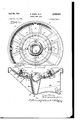
- Figure 1 is a fragmentary top plan view of the invention as applied to a mortar base plate
- Figure 2 is a vertical cross-sectional view of the same
- Figure 3 is a top plan view to an enlarged scale of an azimuth indicator with the mortar in maximum or substantially 90 elevation.
- FIG 4 is a cross sectional view of the indicator of Figure 3 taken in a vertical plane extending centrally and longitudinally of the indicator
- the preferred embodiment of this invention depicted in the accompanying drawings includes a circular metal socket base plate member I, having a circular concave platform 2, provided with a downwardly extending circumferential apron 3 and having a central open portion 4 in which there is rigidly secured a stationary socket or lower section'5 having an integral or radially extending flange 6.
- a rotatable socket cap or upper section 1 which is movably secured in position by means of a retainer ring 8 having a raised offset inner portion 9 which overlaps a circular outwardly extending flange I0 formed integral with the socket cap.
- the construction is such that the upper section 1 may at all times be freely rotated upon and with relation to lower section 5.
- a circular supporting member II is mounted above the retainer ring and the socket flange 6 and together with each of these members is rigidly secured by cap screws l2 to the platform 2 in a manner which may be readily understood by referring to Figure 2.
- This supporting member has two spaced cylindrical coaxial flanges I3 and I4 extending upwardly from its peripheral portion and having respectively, outwardly and inwardly extending fiat rim portions [5 and "5. These flat rim portions (see Figure 2) extend toward but are spaced apart from each other to provide a base for an azimuth ring I! having any suitable indicia l8. The space between the rims defines a circular slot l9.
- extend through the azimuth ring and the slot I9 in a manner whereby the azimuth ring may be readily rotated to any desired angular position with reference to the base plate and then rigidly clamped to the rim portions l5 and I6 by tightening nuts 2
- the socket cap I has a right-angular cut away upper portion 22 which serves to admit a ball 23 having parallel opposite flats 24.
- This ball forms the extreme end portion of the conventional mortar indicated in broken lines in Figures 4 and 5.
- the ball is inserted in the socket by holding the planes of its flats? parallel to the planes of the vertical edges 25 of the cutaway portion of the socket cap and pushing the ball into the socket.
- the ball is now rotated to thereby secure the mortar against removal from the'base plate.
- the ball may be secured against removal from its socket by rotating cap or ring I.
- an azimuth indicator 26 having a circular band segment 21 which may be secured to the shank 28 of the mortar by any suitable means such as screws 29.
- Segment 2'! is provided with two perforated integral spaced apart ears 30 and a perforated lug 3
- the azimuth indicator also includes outwardly and parallelly extending bars 32, 33 which are operatively connected with each other in such a man ner that the outer bar 33 can be moved radially n the bar 32 and clamped in the desired position of radial adjustment by a nut. and bolt. means 34, the shank 35 of which extends through an opening 36 provided in the bar 33 and an elongated slot 31 provided in the bar 32.
- the inner portion of the bar 32 is slotted at 88 and perforated at 39 for the purpose of permitting a coiled spring 4!! to be operatively connected to the perforated lug 3
- this outer end M of the bar 33 has an opening 42' and is also provided with an inner pointer 63 and an outer pointer 44 whereby the angular position of'the mortar may be easily read on the azimuth ring regardless of theamount of theelevati'on or depression of the mortar.
- the bar 32 is provided with cars 55 which are pivotally secured to the ears of the band segment 2'! by means of a rivet 46.
- the socket platform may, if desired, be formed in any suitable manner adapted to provide a support for the socket and its rotatably mounted cap. However, it may be advantageously provided with suitable ground engaging means, such as for instance, fixedly secured spades 11' and 48, a spadeshield 49 and a central hollow post or spike 53'. This spike is preferably provided with a.- pointed plug.
- ground engaging means are preferably welded to the plate in a manner adapted to make a strong integral supporting base capable of withstanding the shocks and concussions incident to mortar firing.
- the heads 52 of the bolts 20- are wider than the slot through which the shanks of these bolts extend.
- suitable aligned openings 53 and 54 are provided in the base plate and in the arm Id.
- the opposite sides of the shanks of the bolts are preferably flattened as is indicated at 55, Figure 1.
- a mounting base for a mortar barrel provided with a mounting ball, having diametrically opposite parallel flats, a generally circular base plate, means carried by said plate centrally thereof forming a generally spherical socket comprising a lower hemispherical portion fixed to said plate and an upper ring portion, means securing said ring portion on said lower portion for rotation thereon, said portions being divided on a normally horizontal equatorial plane of saidsocket, said ring portion having oppositely disposed portions cut away to form notches whose side edges are defined by the intersection with said ring of normally vertical parallel planes spaced a distance equal to the separation of the flats on said mounting ball, whereby said ball may be inserted into said socket when said flats thereon are coplanar with the corresponding side edges of said cut away portions, said ball being retained in said socket against removal therefrom, by relative angular movement of said ball and ring portion about an axis normal to said equatorial plane.
- a barrel having a mounting ball rigid therewith, a circular dished base plate, means forming a spherical socket secured to said base plate centrally thereof, said socket comprising a lower hemispherical portion rigid with said base plate, and an upper ring portion rotatable on said lower portion about a normally vertical axis, said ring portion being cut away to coact' with diametrically opposite flats on said ball to pass said ball into said socket only for a definite angular relation of said ball and ring portion, whereby said ball may be inserted into said socket for one rotational position only of said ball relatively to said ring portion, and secured therein by relative rotation of said ball and ring about said normally vertical axis.
- a base plate means fixed to said plate and forming a hemispherical upWardly-facing socket in which said ball fits smoothly
- a ring carried by said base plate for rotation about the normally vertical axis of said socket, said ring having an internal partly-spherical surface forming a continuation of the hemispherical surface of said socket, there being a pair of diametrically-opposite notches in said ring having their sides defined by the intersection with said ring of apair of parallel planes symmetrically disposed on opposite sides of said normally-vertical axis and spaced by a distance substantially equal to the distance between the flats on said ball, whereby said ball may be inserted into said socket with its fiats parallel with said planes, and held against removal from said socket by rotation of said ring.
- a mounting ball attached to the breech end of the barrel and having a pair of diametrically opposite parallel flats, a base plate, a first member having a hemispherical upwardly-facing socket secured to said base plate, a ring member equal to the separation of the flats on said wall,
- said ball may be freely inserted into said socket and retained therein by relative rotation about a normally vertical axis between said ball and ring.
Landscapes
- Engineering & Computer Science (AREA)
- General Engineering & Computer Science (AREA)
- Road Signs Or Road Markings (AREA)
Description
S. WEISS ETAL June 26, 1951 MORTAR BASE PLATE 2 Sheets-Sheet 1 Filed Dec. 12, 1946 \EI-ALILWEISS, 6/ EDGAR LlEuaER -rs, /i 4ZM%%MW%HMJLM m 1951 s. WEISS ETAL 2,558,024
MORTAR BASE PLATE Filed Dec. 12, 1946 2 Sheets-Sheet 2 EDGAR ELRDEBE TE,
Patented June 26, 1951 MORTAR BASE PLATE Saul Weiss and Edgar G. Roberts, Arlington County, Va.
Application December 12, 1946, Serial No. 715,782
(Granted under the act of March 3, 1883, as
4 Claims.
amended April 30, 1928; 370 0. G. 757) The invention described herein may be manu- This invention relates to improvements in mortar socket base plates whereby the mortar may be traversed inits socket 360.
' Since the introduction of paratroopers and airborne infantry into warfare, it has become of utmost importance that combatant personnel be provided with weapons adapted to repel sudden attacks by the enemy from the rear. However, the conventional light high angle fire mortar is ill adapted for this purpose for the reason that its rear and lower end portion terminates in a ball which is mounted in a socket, the construction of which is such that it permits only a limited traverse of the mortar. Hence it has heretofore been necessary, before the direction of fire could be reversed or even changed through a substantial angle in azimuth, to change the position of the base plate or make other time consuming readjustments while heavy casualties could be inflicted.
It is therefore a major purpose of this invention to provide a mortar base plate which will permit the mortar to be rapidly rotated without changing the position of the base plate or removing the mortar from its socket.
Another object is to provide an improved ball socket means which will permit an almost instantaneous 360 traverse of the mortar while the mortar remains in its'socket.
The additional objects, advantages and features of this invention reside in the construction, arrangement and combination of parts involved in the preferred embodiment of the invention illustrated in the accompanying drawings, in which:
Figure 1 is a fragmentary top plan view of the invention as applied to a mortar base plate,
Figure 2 is a vertical cross-sectional view of the same,
Figure 3 is a top plan view to an enlarged scale of an azimuth indicator with the mortar in maximum or substantially 90 elevation.
Figure 4 is a cross sectional view of the indicator of Figure 3 taken in a vertical plane extending centrally and longitudinally of the indicator The preferred embodiment of this invention depicted in the accompanying drawings includes a circular metal socket base plate member I, having a circular concave platform 2, provided with a downwardly extending circumferential apron 3 and having a central open portion 4 in which there is rigidly secured a stationary socket or lower section'5 having an integral or radially extending flange 6. On this socket there is mounted a rotatable socket cap or upper section 1 which is movably secured in position by means of a retainer ring 8 having a raised offset inner portion 9 which overlaps a circular outwardly extending flange I0 formed integral with the socket cap. The construction is such that the upper section 1 may at all times be freely rotated upon and with relation to lower section 5.
A circular supporting member II is mounted above the retainer ring and the socket flange 6 and together with each of these members is rigidly secured by cap screws l2 to the platform 2 in a manner which may be readily understood by referring to Figure 2.
This supporting member has two spaced cylindrical coaxial flanges I3 and I4 extending upwardly from its peripheral portion and having respectively, outwardly and inwardly extending fiat rim portions [5 and "5. These flat rim portions (see Figure 2) extend toward but are spaced apart from each other to provide a base for an azimuth ring I! having any suitable indicia l8. The space between the rims defines a circular slot l9. oppositely positioned bolts 20 provided with knurled nuts 2| extend through the azimuth ring and the slot I9 in a manner whereby the azimuth ring may be readily rotated to any desired angular position with reference to the base plate and then rigidly clamped to the rim portions l5 and I6 by tightening nuts 2|.
Referring now to Figure 2, it will be noted that the socket cap I has a right-angular cut away upper portion 22 which serves to admit a ball 23 having parallel opposite flats 24. This ball forms the extreme end portion of the conventional mortar indicated in broken lines in Figures 4 and 5. In mounting the mortar on the plate, the ball is inserted in the socket by holding the planes of its flats? parallel to the planes of the vertical edges 25 of the cutaway portion of the socket cap and pushing the ball into the socket. The ball is now rotated to thereby secure the mortar against removal from the'base plate. Alternatively the ball may be secured against removal from its socket by rotating cap or ring I.
Referring to Figures 3, 4, and 5, it will be seen that there is also provided an azimuth indicator 26 having a circular band segment 21 which may be secured to the shank 28 of the mortar by any suitable means such as screws 29. Segment 2'! is provided with two perforated integral spaced apart ears 30 and a perforated lug 3|. The azimuth indicator also includes outwardly and parallelly extending bars 32, 33 which are operatively connected with each other in such a man ner that the outer bar 33 can be moved radially n the bar 32 and clamped in the desired position of radial adjustment by a nut. and bolt. means 34, the shank 35 of which extends through an opening 36 provided in the bar 33 and an elongated slot 31 provided in the bar 32. The inner portion of the bar 32 is slotted at 88 and perforated at 39 for the purpose of permitting a coiled spring 4!! to be operatively connected to the perforated lug 3| on the band segment and to the bar 32 to urge the outer end 4| of bar 33against the fiat upper surface of the azimuth ring l1.
Referring now particularly to Figures 3 and 4, it will be noted that this outer end M of the bar 33 has an opening 42' and is also provided with an inner pointer 63 and an outer pointer 44 whereby the angular position of'the mortar may be easily read on the azimuth ring regardless of theamount of theelevati'on or depression of the mortar. It will also be'noted that the bar 32 is provided with cars 55 which are pivotally secured to the ears of the band segment 2'! by means of a rivet 46.
The socket platform may, if desired, be formed in any suitable manner adapted to provide a support for the socket and its rotatably mounted cap. However, it may be advantageously provided with suitable ground engaging means, such as for instance, fixedly secured spades 11' and 48, a spadeshield 49 and a central hollow post or spike 53'. This spike is preferably provided with a.- pointed plug Each of the above mentioned ground engaging means are preferably welded to the plate in a manner adapted to make a strong integral supporting base capable of withstanding the shocks and concussions incident to mortar firing.
From. Figure 2, it will be noted that the heads 52 of the bolts 20- are wider than the slot through which the shanks of these bolts extend. In order that the head of these bolts may be inserted beneath this slot, suitable aligned openings 53 and 54 are provided in the base plate and in the arm Id. In order to prevent these bolts from turning in this slot, the opposite sides of the shanks of the bolts are preferably flattened as is indicated at 55, Figure 1.
Referring now particularly to Figure 5, it will be noted that, as the muzzle of the mortar is lowered into position for firing; its shank 28 must be depressed in the cut-away portion 22' of the mortar cap, and therefore only a limited traverse is possible between the mortar and the vertical edges 25 of the cut-away portion 1. However, since the cap is rotatably mounted on its socket, it in no'way prevents the rotation of the mortar three hundred and sixty degrees. The term normally as used in the claims is to be interpreted to mean the position or relation of the parts referred to when the mortar is in actual use on substantially level terrain.
The above described invention is disclosed in the best construction known to the inventors but it is' to be understood that this is purely exemplary and that other modifications may be '4 made, such, as for instance, forming or welding the socket and its cap integral with each other and rotatably mounting the combined socket and cap structure on the base plate in any suitable manner without departing from the spirit of the invention or the scope of the appended claims. In the claims, the terms normally horizonta and normally vertica refer to the positions of the parts as shown upon the drawing.
We claim:
1. In a mounting base for a mortar barrel provided with a mounting ball, having diametrically opposite parallel flats, a generally circular base plate, means carried by said plate centrally thereof forming a generally spherical socket comprising a lower hemispherical portion fixed to said plate and an upper ring portion, means securing said ring portion on said lower portion for rotation thereon, said portions being divided on a normally horizontal equatorial plane of saidsocket, said ring portion having oppositely disposed portions cut away to form notches whose side edges are defined by the intersection with said ring of normally vertical parallel planes spaced a distance equal to the separation of the flats on said mounting ball, whereby said ball may be inserted into said socket when said flats thereon are coplanar with the corresponding side edges of said cut away portions, said ball being retained in said socket against removal therefrom, by relative angular movement of said ball and ring portion about an axis normal to said equatorial plane.
2. In a mortar, a barrel having a mounting ball rigid therewith, a circular dished base plate, means forming a spherical socket secured to said base plate centrally thereof, said socket comprising a lower hemispherical portion rigid with said base plate, and an upper ring portion rotatable on said lower portion about a normally vertical axis, said ring portion being cut away to coact' with diametrically opposite flats on said ball to pass said ball into said socket only for a definite angular relation of said ball and ring portion, whereby said ball may be inserted into said socket for one rotational position only of said ball relatively to said ring portion, and secured therein by relative rotation of said ball and ring about said normally vertical axis.
3. In a mounting for a mortar barrel provided with a mounting ball having diametrically opposite parallel fiats formed thereon, a base plate, means fixed to said plate and forming a hemispherical upWardly-facing socket in which said ball fits smoothly, a ring carried by said base plate for rotation about the normally vertical axis of said socket, said ring having an internal partly-spherical surface forming a continuation of the hemispherical surface of said socket, there being a pair of diametrically-opposite notches in said ring having their sides defined by the intersection with said ring of apair of parallel planes symmetrically disposed on opposite sides of said normally-vertical axis and spaced by a distance substantially equal to the distance between the flats on said ball, whereby said ball may be inserted into said socket with its fiats parallel with said planes, and held against removal from said socket by rotation of said ring.
4. In a ball and socket mounting for a mortar barrel, a mounting ball attached to the breech end of the barrel and having a pair of diametrically opposite parallel flats, a base plate, a first member having a hemispherical upwardly-facing socket secured to said base plate, a ring member equal to the separation of the flats on said wall,
whereby said ball may be freely inserted into said socket and retained therein by relative rotation about a normally vertical axis between said ball and ring.
SAUL WEISS. EDGAR C. ROBERTS.
REFERENCES CITED The following references are of record in the file of this patent:
UNITED STATES PATENTS Number Number Name Date Goddard Apr. 21, 1874 Spiller Aug. 2, 1892 Ehrhart June 23, 1903 Joyce July '7, 1936 Denoix Mar. 26, 1940 Caulkins June 29, 1948 FOREIGN PATENTS Country Date Great Britain of 1915 France Mar. 11, 1920 Germany July 5, 1920 Germany Nov. 2, 1920 Great Britain Oct. 6, 1921 France Jan. 18, 1924 France Sept. 14, 1935 France Apr. 26, 1937 Great Britain Oct. 25, 1938
Priority Applications (1)
| Application Number | Priority Date | Filing Date | Title |
|---|---|---|---|
| US715782A US2558024A (en) | 1946-12-12 | 1946-12-12 | Mortar base plate |
Applications Claiming Priority (1)
| Application Number | Priority Date | Filing Date | Title |
|---|---|---|---|
| US715782A US2558024A (en) | 1946-12-12 | 1946-12-12 | Mortar base plate |
Publications (1)
| Publication Number | Publication Date |
|---|---|
| US2558024A true US2558024A (en) | 1951-06-26 |
Family
ID=24875456
Family Applications (1)
| Application Number | Title | Priority Date | Filing Date |
|---|---|---|---|
| US715782A Expired - Lifetime US2558024A (en) | 1946-12-12 | 1946-12-12 | Mortar base plate |
Country Status (1)
| Country | Link |
|---|---|
| US (1) | US2558024A (en) |
Cited By (11)
| Publication number | Priority date | Publication date | Assignee | Title |
|---|---|---|---|---|
| US2694342A (en) * | 1948-08-04 | 1954-11-16 | Brandt Edgar Ets | Base-plate device for mortars and other guns |
| US2765707A (en) * | 1953-05-12 | 1956-10-09 | Soltam Ltd | Base plate of grenade mortar |
| US2780964A (en) * | 1952-12-24 | 1957-02-12 | Brandt Soc Nouv Ets | Base plate for mortars and like apparatuses |
| US2818780A (en) * | 1954-12-27 | 1958-01-07 | Saloranta Arvo Ensio | Coupling devices of mortar-type guns |
| DE1087045B (en) * | 1957-11-13 | 1960-08-11 | Baronin Ilyana Von Thyssen Bor | Locking the base of a grenade launcher tube with a base plate |
| US4026190A (en) * | 1975-09-22 | 1977-05-31 | Oather Blair | Mortar sighting device |
| US4864912A (en) * | 1988-03-31 | 1989-09-12 | Esperanza Y Cia., S.A. | Breechblock with firing pin for mortars |
| US8277141B1 (en) * | 2011-01-04 | 2012-10-02 | The United States Of America As Represented By The Secretary Of The Army | Ball and socket joint for indirect fire weapon |
| US8707849B1 (en) * | 2011-06-20 | 2014-04-29 | The United States Of America As Represented By The Secretary Of The Army | Modular mortar baseplate |
| WO2019068952A1 (en) * | 2017-10-06 | 2019-04-11 | New Technologies Global Systems, S.L. | Device for securing the ball joint of a mortar barrel |
| US11300389B1 (en) * | 2018-05-04 | 2022-04-12 | The United States Of America As Represented By The Secretary Of The Army | Slip baseplate |
Citations (15)
| Publication number | Priority date | Publication date | Assignee | Title |
|---|---|---|---|---|
| DE303927C (en) * | ||||
| DE300702C (en) * | ||||
| US150024A (en) * | 1874-04-21 | Improvement in ordnance | ||
| US480215A (en) * | 1892-08-02 | Mortar-carriage | ||
| US731874A (en) * | 1903-02-20 | 1903-06-23 | Gustav Ehrhardt | Locking device for gun-pivots. |
| GB191516280A (en) * | 1916-06-19 | 1919-03-27 | Gogu Constantinesco | Improvements in and relating to Ordnance. |
| FR503207A (en) * | 1917-02-27 | 1920-06-05 | Comp Generale Electricite | Grenade launcher |
| GB146900A (en) * | 1915-12-29 | 1921-10-06 | Alfred Wolff Maschf | Improvements in and relating to bed plates, more particularly for trench mortars |
| FR570613A (en) * | 1923-09-03 | 1924-05-05 | New cannon | |
| FR786952A (en) * | 1935-03-08 | 1935-09-14 | Improvements in artillery equipment | |
| US2046518A (en) * | 1935-05-25 | 1936-07-07 | American Armament Corp | Separable gun mount |
| FR816093A (en) * | 1936-04-06 | 1937-07-29 | Platform for artillery pieces | |
| GB494355A (en) * | 1937-04-08 | 1938-10-25 | Albrecht Mueller | Improvements in and relating to light bomb throwers, trench mortars and the like weapons |
| US2194849A (en) * | 1936-12-31 | 1940-03-26 | Sageb Sa | Piece of ordnance |
| US2444334A (en) * | 1945-02-14 | 1948-06-29 | American Ordnance Corp | Mortar mount |
-
1946
- 1946-12-12 US US715782A patent/US2558024A/en not_active Expired - Lifetime
Patent Citations (15)
| Publication number | Priority date | Publication date | Assignee | Title |
|---|---|---|---|---|
| DE300702C (en) * | ||||
| US150024A (en) * | 1874-04-21 | Improvement in ordnance | ||
| US480215A (en) * | 1892-08-02 | Mortar-carriage | ||
| DE303927C (en) * | ||||
| US731874A (en) * | 1903-02-20 | 1903-06-23 | Gustav Ehrhardt | Locking device for gun-pivots. |
| GB146900A (en) * | 1915-12-29 | 1921-10-06 | Alfred Wolff Maschf | Improvements in and relating to bed plates, more particularly for trench mortars |
| GB191516280A (en) * | 1916-06-19 | 1919-03-27 | Gogu Constantinesco | Improvements in and relating to Ordnance. |
| FR503207A (en) * | 1917-02-27 | 1920-06-05 | Comp Generale Electricite | Grenade launcher |
| FR570613A (en) * | 1923-09-03 | 1924-05-05 | New cannon | |
| FR786952A (en) * | 1935-03-08 | 1935-09-14 | Improvements in artillery equipment | |
| US2046518A (en) * | 1935-05-25 | 1936-07-07 | American Armament Corp | Separable gun mount |
| FR816093A (en) * | 1936-04-06 | 1937-07-29 | Platform for artillery pieces | |
| US2194849A (en) * | 1936-12-31 | 1940-03-26 | Sageb Sa | Piece of ordnance |
| GB494355A (en) * | 1937-04-08 | 1938-10-25 | Albrecht Mueller | Improvements in and relating to light bomb throwers, trench mortars and the like weapons |
| US2444334A (en) * | 1945-02-14 | 1948-06-29 | American Ordnance Corp | Mortar mount |
Cited By (11)
| Publication number | Priority date | Publication date | Assignee | Title |
|---|---|---|---|---|
| US2694342A (en) * | 1948-08-04 | 1954-11-16 | Brandt Edgar Ets | Base-plate device for mortars and other guns |
| US2780964A (en) * | 1952-12-24 | 1957-02-12 | Brandt Soc Nouv Ets | Base plate for mortars and like apparatuses |
| US2765707A (en) * | 1953-05-12 | 1956-10-09 | Soltam Ltd | Base plate of grenade mortar |
| US2818780A (en) * | 1954-12-27 | 1958-01-07 | Saloranta Arvo Ensio | Coupling devices of mortar-type guns |
| DE1087045B (en) * | 1957-11-13 | 1960-08-11 | Baronin Ilyana Von Thyssen Bor | Locking the base of a grenade launcher tube with a base plate |
| US4026190A (en) * | 1975-09-22 | 1977-05-31 | Oather Blair | Mortar sighting device |
| US4864912A (en) * | 1988-03-31 | 1989-09-12 | Esperanza Y Cia., S.A. | Breechblock with firing pin for mortars |
| US8277141B1 (en) * | 2011-01-04 | 2012-10-02 | The United States Of America As Represented By The Secretary Of The Army | Ball and socket joint for indirect fire weapon |
| US8707849B1 (en) * | 2011-06-20 | 2014-04-29 | The United States Of America As Represented By The Secretary Of The Army | Modular mortar baseplate |
| WO2019068952A1 (en) * | 2017-10-06 | 2019-04-11 | New Technologies Global Systems, S.L. | Device for securing the ball joint of a mortar barrel |
| US11300389B1 (en) * | 2018-05-04 | 2022-04-12 | The United States Of America As Represented By The Secretary Of The Army | Slip baseplate |
Similar Documents
| Publication | Publication Date | Title |
|---|---|---|
| US2558024A (en) | Mortar base plate | |
| US2807904A (en) | Folding bipod assembly | |
| US4202539A (en) | Engine work stand | |
| US3958904A (en) | Ball-and-socket joint | |
| US2743525A (en) | Telescope sight mount | |
| US2557960A (en) | Base plate for mortars | |
| EP1538351A1 (en) | Wheel nut locking assembly | |
| US4423850A (en) | Fine adjusting mechanism for a level platform | |
| US2643920A (en) | Turret roller bearing | |
| US9902440B2 (en) | Adjustable spare tire carrier | |
| US2323624A (en) | Swivel | |
| US1335403A (en) | Machine-gun tripod | |
| US4339097A (en) | Target seeking head for a missile | |
| US1466913A (en) | Peep sight for firearms | |
| US4787290A (en) | Support apparatus for a grenade thrower tube | |
| US2441874A (en) | Gun mount for land and water vehicles | |
| US2694342A (en) | Base-plate device for mortars and other guns | |
| DE3722380C2 (en) | ||
| US1903326A (en) | Front sight for rifles | |
| US1374862A (en) | Machine-gun mount | |
| DK151727B (en) | THIRD LED CONNECTION | |
| US1939540A (en) | Mechanism for angular adjustment of gun sights | |
| US3523670A (en) | Coupling device for a tripod | |
| US4703636A (en) | Center locking device of the intermediary plate type for a disc wheel of motor vehicle | |
| US3581596A (en) | Balancing apparatus for a rotating element |