US2540887A - Cable-anchoring and -tightening device - Google Patents
Cable-anchoring and -tightening device Download PDFInfo
- Publication number
- US2540887A US2540887A US68611A US6861148A US2540887A US 2540887 A US2540887 A US 2540887A US 68611 A US68611 A US 68611A US 6861148 A US6861148 A US 6861148A US 2540887 A US2540887 A US 2540887A
- Authority
- US
- United States
- Prior art keywords
- casing
- cable
- lever
- post
- engagement
- Prior art date
- Legal status (The legal status is an assumption and is not a legal conclusion. Google has not performed a legal analysis and makes no representation as to the accuracy of the status listed.)
- Expired - Lifetime
Links
- 238000004873 anchoring Methods 0.000 title description 13
- 230000006835 compression Effects 0.000 description 1
- 238000007906 compression Methods 0.000 description 1
- 230000003247 decreasing effect Effects 0.000 description 1
- 230000000994 depressogenic effect Effects 0.000 description 1
- 230000000977 initiatory effect Effects 0.000 description 1
- 230000037431 insertion Effects 0.000 description 1
- 238000003780 insertion Methods 0.000 description 1
- 125000006850 spacer group Chemical group 0.000 description 1
Images
Classifications
-
- F—MECHANICAL ENGINEERING; LIGHTING; HEATING; WEAPONS; BLASTING
- F16—ENGINEERING ELEMENTS AND UNITS; GENERAL MEASURES FOR PRODUCING AND MAINTAINING EFFECTIVE FUNCTIONING OF MACHINES OR INSTALLATIONS; THERMAL INSULATION IN GENERAL
- F16G—BELTS, CABLES, OR ROPES, PREDOMINANTLY USED FOR DRIVING PURPOSES; CHAINS; FITTINGS PREDOMINANTLY USED THEREFOR
- F16G11/00—Means for fastening cables or ropes to one another or to other objects; Caps or sleeves for fixing on cables or ropes
- F16G11/04—Means for fastening cables or ropes to one another or to other objects; Caps or sleeves for fixing on cables or ropes with wedging action, e.g. friction clamps
- F16G11/044—Means for fastening cables or ropes to one another or to other objects; Caps or sleeves for fixing on cables or ropes with wedging action, e.g. friction clamps friction clamps deforming the cable, wire, rope or cord
- F16G11/046—Means for fastening cables or ropes to one another or to other objects; Caps or sleeves for fixing on cables or ropes with wedging action, e.g. friction clamps friction clamps deforming the cable, wire, rope or cord by bending the cable around a surface
-
- B—PERFORMING OPERATIONS; TRANSPORTING
- B64—AIRCRAFT; AVIATION; COSMONAUTICS
- B64F—GROUND OR AIRCRAFT-CARRIER-DECK INSTALLATIONS SPECIALLY ADAPTED FOR USE IN CONNECTION WITH AIRCRAFT; DESIGNING, MANUFACTURING, ASSEMBLING, CLEANING, MAINTAINING OR REPAIRING AIRCRAFT, NOT OTHERWISE PROVIDED FOR; HANDLING, TRANSPORTING, TESTING OR INSPECTING AIRCRAFT COMPONENTS, NOT OTHERWISE PROVIDED FOR
- B64F1/00—Ground or aircraft-carrier-deck installations
- B64F1/12—Ground or aircraft-carrier-deck installations for anchoring aircraft
-
- F—MECHANICAL ENGINEERING; LIGHTING; HEATING; WEAPONS; BLASTING
- F16—ENGINEERING ELEMENTS AND UNITS; GENERAL MEASURES FOR PRODUCING AND MAINTAINING EFFECTIVE FUNCTIONING OF MACHINES OR INSTALLATIONS; THERMAL INSULATION IN GENERAL
- F16G—BELTS, CABLES, OR ROPES, PREDOMINANTLY USED FOR DRIVING PURPOSES; CHAINS; FITTINGS PREDOMINANTLY USED THEREFOR
- F16G11/00—Means for fastening cables or ropes to one another or to other objects; Caps or sleeves for fixing on cables or ropes
- F16G11/12—Connections or attachments, e.g. turnbuckles, adapted for straining of cables, ropes, or wire
-
- Y—GENERAL TAGGING OF NEW TECHNOLOGICAL DEVELOPMENTS; GENERAL TAGGING OF CROSS-SECTIONAL TECHNOLOGIES SPANNING OVER SEVERAL SECTIONS OF THE IPC; TECHNICAL SUBJECTS COVERED BY FORMER USPC CROSS-REFERENCE ART COLLECTIONS [XRACs] AND DIGESTS
- Y10—TECHNICAL SUBJECTS COVERED BY FORMER USPC
- Y10T—TECHNICAL SUBJECTS COVERED BY FORMER US CLASSIFICATION
- Y10T24/00—Buckles, buttons, clasps, etc.
- Y10T24/21—Strap tighteners
- Y10T24/2175—Cargo tie down
-
- Y—GENERAL TAGGING OF NEW TECHNOLOGICAL DEVELOPMENTS; GENERAL TAGGING OF CROSS-SECTIONAL TECHNOLOGIES SPANNING OVER SEVERAL SECTIONS OF THE IPC; TECHNICAL SUBJECTS COVERED BY FORMER USPC CROSS-REFERENCE ART COLLECTIONS [XRACs] AND DIGESTS
- Y10—TECHNICAL SUBJECTS COVERED BY FORMER USPC
- Y10T—TECHNICAL SUBJECTS COVERED BY FORMER US CLASSIFICATION
- Y10T24/00—Buckles, buttons, clasps, etc.
- Y10T24/39—Cord and rope holders
- Y10T24/3936—Pivoted part
- Y10T24/394—Cam lever
-
- Y—GENERAL TAGGING OF NEW TECHNOLOGICAL DEVELOPMENTS; GENERAL TAGGING OF CROSS-SECTIONAL TECHNOLOGIES SPANNING OVER SEVERAL SECTIONS OF THE IPC; TECHNICAL SUBJECTS COVERED BY FORMER USPC CROSS-REFERENCE ART COLLECTIONS [XRACs] AND DIGESTS
- Y10—TECHNICAL SUBJECTS COVERED BY FORMER USPC
- Y10T—TECHNICAL SUBJECTS COVERED BY FORMER US CLASSIFICATION
- Y10T24/00—Buckles, buttons, clasps, etc.
- Y10T24/39—Cord and rope holders
- Y10T24/3996—Sliding wedge
Definitions
- This invention deals with anchoring and tightening devices for flexible cable, ropes, and the like, and more particularly with an improved apparatus operable to simultaneously anchor the free end of a flexible cable and to tighten the same throughout its length.
- the present invention contemplates an improved type of mooring or tie-down device for use in securing or anchoring aircraft in a fixed position upon a flying field or upon the deck of an aircraft carrier in a quick and facile manner. It should be understood, however, that the usage of the present improved cable anchoring apparatus is in no way restricted to the above mentioned use, the same being adapted for use in various capacities requiring a connecting link between a flexible cable and a stationary member, or between the free ends of two or more cables.
- the primary object of the present invention is to provide an improved cable-anchoring device capable of fast and facile action in securely clamping the free end portion of a cable and simultaneously decreasing the effective length thereof with relation to a stationary object, whereby to tighten the connection between the cable and such an object.
- Fig. 1 is an elevational view of the present mooring apparatus operatively connected between a stationary ground support and a relatively movable object, such as the wing of an airplane or the like;
- Fig. 2 is a medial longitudinal vertical sectional view taken through the present cable-anchoring and tightening device
- Fig. 3 is a transverse vertical sectional view taken along the line 3-3 of Fig. 2;
- Fig. 4 is a horizontal sectional view taken along the line 4-4 of Fig. 2;
- Fig. 5 is a side elevational view of a combination handle and clip device which may be advantageously used in connection with the mooring apparatus of the present invention
- Fig. 6 is an edge elevational view of the combination handle and clip device.
- the numeral I generally designates a casing which advantageously may comprise a pair of spaced complemental side plates ll secured to one another by means of rivets or other suitable fastening devices, as at I2, and normally spaced from one another by the remaining operating elements making up the present invention, and to be hereinafter more fully described.
- a pair of relatively spaced and acutely angularly related blocks or abutments l3 Disposed adjacent the lower end of the casing and separating the side plates thereof are a pair of relatively spaced and acutely angularly related blocks or abutments l3 which may constitute separable members with respect to the casing, or which may be formed integral therewith.
- the inner or adjacent edges of the blocks l3 define a tapered socket which opens :at its smaller end at one end of the casing, as at l4.
- a combination cable-receiving post and wedging member [5 which is formed with a centrally disposed slot [6 through which a spacer pin ll extends, the latter being secured at its respective ends to the side walls I! of the casing.
- the connection between the slidable cable-receiving post I5 and the casing 10 thus provides for limited longitudinal movement of the post into and out of the tapered socket defined by the blocks l3, and into and out of substantial wedging engagement with the inner edges of the blocks.
- a coil compression spring I8 Interposed between the pin I! and one end of the slot 16 of the post is a coil compression spring I8 which resiliently urges the post out of wedging engagement with the inner surfaces or edges of the blocks I3.
- the post :5 in side elevation, is substantially coneshaped with one end thereof being rounded through approximately while the side edges thereof are disposed in acutely angular relationship corresponding to the inner surfaces or edges of the blocks It.
- the entire marginal edge portion of the post I5 may be arcuately grooved so as to provide a cable-receiving surface corresponding to the contour of a given size cable.
- the inner edges of the blocks l3 are preferably arcuately grooved so as to conform to the curvature of a given size cable, and thereby provide an increased contacting surface between the cable, the blocks 53, and the post l5.
- i is a sliding block it which has its side edges arcuately recessed, as at 25, in substantially concentric relation to the arcuately rounded porthe casing it between the side walls thereof;
- a hand-operated lever 24 which is mounted for swinging movement into substantially abutting relation to one of the sides of the casing It;
- the lever 24 may advantageously be iormed upon its inner surface so as to conform to the shape of the outeredgeof the casing it whereby to.lie in substantially flat compact relation thereto when occupying its position alongside the casing.
- the inner end of the lever 24 is formed so as to provide a substantially enlarged eccentrically dis.- posed cam face 25' which, upon swinging movement of the lever 24,.ri'desl in sliding engagement with one of 'the arcuately-recessed edges of the slidable block it.
- the contour of the cam face 25' is such that upon swinging movement of the lever 24 to' a position alongside of the casing i as shown in Fig. 2, thelblock Mlwillbe forced. to itsinnermost position within the casing whereby to force the-post member l5 into substantial wed'ging engagement with the inner. edges ofthe blocks l3. Movementof the lever 24in a clock wise direction, as. viewed from Fig. 2;, permits the block H) to move upwardly within the casing. and out of relative engagement with the post l5.
- the camportion of; the lever 24 is also formed with a relatively short arcuate slot 25 threugh which extends a pin 2? which is slidably carried transversely of a relatively elongated arcuate slot 28 formed irrand through the side walls I I of the casing; Pivotally connected with the respective ends of the pin 2'! are the ends of a bifurcated link 29 which normally extends outwardly from the opposite end of the casing, with its" opposite end pivotally'carrying a hook device 33 for attachment'to' a ring or bail 31', such as are normally carried upon the wing or tail portions of an-aircraft;
- the arcuate slot 28" formed within the side walls i of the'casing has one of its ends terminatingfsubstantially.at the outer end of the casing; and its opposite end terminating just beyond the centerline of the casing below the pivot pin 23;
- the lever 24' is swung in a counterclockwise direction, aslviewed in Fig 2,.to its abutting-position with respect to the edgeof the casing, the'pi'n 27 is forced from the outer to the inner endof. the slot 28 todraw the link 29 in-- wardlyf of the casing, whereby todecrease the distance between the casingv and the outer end of *thelink.
- the free end portion 32 of a flexible cable or rope having its opposite end 33 securedby suitable means. such as a hook link 34 to a relatively stationary objecttfi, is directed inwardly through the opening M at the bottom of the casing in), and in a counterclockwise direction, as shown in Fig. 2, around the marginal edges of the post l5, and back outwardly through the opening M.
- suitable means such as a hook link 34 to a relatively stationary objecttfi
- a combination handle and clip device 36 having a central con! nection opening 3?, is connected to the free end of the cable to provide a convenient handle to pull upon the free end portion of the cable and thereby initially remove slack therefrom between the casing 10 and its" ground support 35.
- Figs. 5 and 6 of the drawinggdiscloserqin. detail 5, ratus, and" which comprises a relatively elongated bail portion 38 which is bent backw-ardly at either end to provide a central opening for hooking engagement with the body portion of the flexible cable, as'shown in Fig. 1, or with any suitable stationary object, to prevent dangling or free movement of the free end of the cable.
- a resiliently flexible spring strip 39 Attached to one of the ends of the bail portion 38, and spanning the openin between such ends, is a resiliently flexible spring strip 39 which, in the normal manner, may be depressed to permit of the entrance of an associated connecting member, and which requires manual depression to re-' lease such connecting member.
- the present invention provides an improved mechanically efiicient cable-anchoring and tightening device which is characterized by its quick and easy action in simultaneously clamping an associated flexible cable, and removing the slack therefrom when interposed between two relatively stationary objects or structures.
- Clamping devices formed in accordance with the present invention are further characterized by their compactness and relatively light weight, made possible through the simplicity and efficient arrangement of the working members of the device.
- a post member slidably carried within said casing for relative wedging movement with respect to said abutments, said post member being formed along the marginal edge thereof with a surface for the looped reception of an intermediate portion of a flexible cable; means in said casing in engagement with said post member for resiliently urging the latter out of wedging engagement with said abutments; a block slidably carried within said casing adjacent said post member for movement into and out of engagement with a portion of a cable looped about said post member, said block being operable upon movement into engagement with a cable looped about said post member to move the cable and post member toward said abutments, where by to clamp the cable between the marginal edge of said post member and said abutments, a handoperated lever pivotally mounted in the opposite end of said casing and having a cam face in engagement with said block, said lever being operable upon swinging movement in one direction to move said block into engagement with a cable carried on said post
- a cable-tightening and anchoring device comprising a hollow casing; means in said casing.
- a combination wedge and cablereceiving member slidably carried in said casing for movement into and out of substantial wedging engagement with the side walls of said socket; spring means connected with said cablereceiving member and resiliently urging the same out of wedging engagement with the side walls of said socket; a block slidably carried within said casing adjacent said cable-receiving member and movable in one direction to force said cablereceiving member into substantial wedging engagement with the side walls of said socket, whereby to clamp a cable looped about said member between the side walls of said socket and the edges of said cable-receiving member; a manually operable lever pivotally carried in the opposite end of said casing and having :an eccentric cam face in engagement with said block, the cam face of said lever being operable in response to the swinging movement of said lever in one direction to slide said block in a direction to force said cable
- a hollow casing having an opening at one end for the introduction of the free end portion of a flexible cable and formed substantially at its opposite end with an arcuate slot, the slot of said casing having one end disposed closer to the center of said casing than the other end thereof; a pin carried within the slot of said casing for sliding movement from one end of the slot to the other; a connector link carried by said pin and extending outwardly from the said opposite end of said casing; means in said casing adjacent the cable-receiving opening thereof providing a pair of relatively spaced acutely angularly related walls; a substantially wedge-shaped cable-receiving member mounted within said casing for sliding movement into and out of substantial wedging engagement with said angularly related walls, the marginal edges of said cable-receiving mem ber providing a surface around which the free end portion of a flexible cable may be looped and directed back out through the opening formed in he end of said casing, said member upon sliding movement in one direction serving
- a cable anchoring device a hollow casing having an opening at one end thereof to receive an end of a flexible cable; a pair of angularly related blocks in said casing adjacent said opening; a cable-receiving post slidably mounted within said casing for movement into and out of substantial wedging engagement with said blocks and for the looped reception of a portion of a cable introduced within said casing by way zweasar ofisaid openinmacom;ectorwli nkecarriedqsubstane tiallyat: the opposites'end; offsai-dcasing 'forslid ing movement: towardiandiaway from the.
- said abutmentsandior the loopedhreceptionvof a portionof a cable introduced within said casmgr-a connector" link. carried. by and extending outwardly from the. opposite end' of said casing and movable inwardly and outwardly with re spectctosaiducasing; and means connected with said link and engage'able with a portionof a cable, leopedlabout said sheave and operable to sinml taxreomaiv; move; saic l w inwardly- 50f. said.
- casing to. decrease; theoutwardv extension; thereot from. the said-oppositeend-of said, casing-t anri move-said-h-sheave and azcablea-loopeda thereabeut into wedging engagement-With said abutmentst H-YHTT.
Landscapes
- Engineering & Computer Science (AREA)
- General Engineering & Computer Science (AREA)
- Mechanical Engineering (AREA)
- Aviation & Aerospace Engineering (AREA)
- Supports For Pipes And Cables (AREA)
Description
Feb. 6, 1951 s. w. HYATT CABLE-ANCHORING AND TIGHTENING DEVICE Filed Dec. 31, 1948 wgiis Patented Feb. 6, 1951 CABLE-ANCHORING AND -TIGHTENING DEVICE Samuel W. Hyatt, Columbus, Ohio, assignor to D. L. Auld Company, ColumbuaOhio, a corporation of Ohio Application December 31, 1948, Serial No. 68,611
Claims. 1
This invention deals with anchoring and tightening devices for flexible cable, ropes, and the like, and more particularly with an improved apparatus operable to simultaneously anchor the free end of a flexible cable and to tighten the same throughout its length.
In its more specific aspects, the present invention contemplates an improved type of mooring or tie-down device for use in securing or anchoring aircraft in a fixed position upon a flying field or upon the deck of an aircraft carrier in a quick and facile manner. It should be understood, however, that the usage of the present improved cable anchoring apparatus is in no way restricted to the above mentioned use, the same being adapted for use in various capacities requiring a connecting link between a flexible cable and a stationary member, or between the free ends of two or more cables.
The primary object of the present invention is to provide an improved cable-anchoring device capable of fast and facile action in securely clamping the free end portion of a cable and simultaneously decreasing the effective length thereof with relation to a stationary object, whereby to tighten the connection between the cable and such an object.
It is another object of this invention to provide an anchoring device of this character which embodies a relatively small and compact casing in which is mounted a slidable wedge member about which the free end portion of a cable may be looped and subsequently clamped within the casing upon wedging action of the slidable memer precipitated by movement of a single handoperated lever which is also eifective to move an associated connector link inwardly of the casing so as to decrease the effective overall length of the mooring or fastening device.
These and additional objects and advantages of the present invention will become more readily apparent by reference to the following description and the accompanying drawing, wherem:
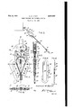
Fig. 1 is an elevational view of the present mooring apparatus operatively connected between a stationary ground support and a relatively movable object, such as the wing of an airplane or the like;
Fig. 2 is a medial longitudinal vertical sectional view taken through the present cable-anchoring and tightening device;
Fig. 3 is a transverse vertical sectional view taken along the line 3-3 of Fig. 2;
Fig. 4 is a horizontal sectional view taken along the line 4-4 of Fig. 2;
Fig. 5 is a side elevational view of a combination handle and clip device which may be advantageously used in connection with the mooring apparatus of the present invention;
Fig. 6 is an edge elevational view of the combination handle and clip device.
Referring now to the drawing, the numeral I!) generally designates a casing which advantageously may comprise a pair of spaced complemental side plates ll secured to one another by means of rivets or other suitable fastening devices, as at I2, and normally spaced from one another by the remaining operating elements making up the present invention, and to be hereinafter more fully described.
Disposed adjacent the lower end of the casing and separating the side plates thereof are a pair of relatively spaced and acutely angularly related blocks or abutments l3 which may constitute separable members with respect to the casing, or which may be formed integral therewith. The inner or adjacent edges of the blocks l3 define a tapered socket which opens :at its smaller end at one end of the casing, as at l4.
Slidably mounted between the side plates ll of the casing is a combination cable-receiving post and wedging member [5 which is formed with a centrally disposed slot [6 through which a spacer pin ll extends, the latter being secured at its respective ends to the side walls I! of the casing. The connection between the slidable cable-receiving post I5 and the casing 10 thus provides for limited longitudinal movement of the post into and out of the tapered socket defined by the blocks l3, and into and out of substantial wedging engagement with the inner edges of the blocks. Interposed between the pin I! and one end of the slot 16 of the post is a coil compression spring I8 which resiliently urges the post out of wedging engagement with the inner surfaces or edges of the blocks I3. As shown particularly in Fig. 2, of the drawing, the post :5, in side elevation, is substantially coneshaped with one end thereof being rounded through approximately while the side edges thereof are disposed in acutely angular relationship corresponding to the inner surfaces or edges of the blocks It. Advantageously, the entire marginal edge portion of the post I5 may be arcuately grooved so as to provide a cable-receiving surface corresponding to the contour of a given size cable. By the same token, the inner edges of the blocks l3 are preferably arcuately grooved so as to conform to the curvature of a given size cable, and thereby provide an increased contacting surface between the cable, the blocks 53, and the post l5.
Slidably carried within the casing adjacent to the arcuatelyrounded portion of the post It;
i is a sliding block it which has its side edges arcuately recessed, as at 25, in substantially concentric relation to the arcuately rounded porthe casing it between the side walls thereof; as
by means of a pivot pirr 23, is a hand-operated lever 24 which is mounted for swinging movement into substantially abutting relation to one of the sides of the casing It; Toward this end, the lever 24 may advantageously be iormed upon its inner surface so as to conform to the shape of the outeredgeof the casing it whereby to.lie in substantially flat compact relation thereto when occupying its position alongside the casing. The inner end of the lever 24 is formed so as to provide a substantially enlarged eccentrically dis.- posed cam face 25' which, upon swinging movement of the lever 24,.ri'desl in sliding engagement with one of 'the arcuately-recessed edges of the slidable block it. The contour of the cam face 25' is such that upon swinging movement of the lever 24 to' a position alongside of the casing i as shown in Fig. 2, thelblock Mlwillbe forced. to itsinnermost position within the casing whereby to force the-post member l5 into substantial wed'ging engagement with the inner. edges ofthe blocks l3. Movementof the lever 24in a clock wise direction, as. viewed from Fig. 2;, permits the block H) to move upwardly within the casing. and out of relative engagement with the post l5.
' The camportion of; the lever 24 is also formed with a relatively short arcuate slot 25 threugh which extends a pin 2? which is slidably carried transversely of a relatively elongated arcuate slot 28 formed irrand through the side walls I I of the casing; Pivotally connected with the respective ends of the pin 2'! are the ends of a bifurcated link 29 which normally extends outwardly from the opposite end of the casing, with its" opposite end pivotally'carrying a hook device 33 for attachment'to' a ring or bail 31', such as are normally carried upon the wing or tail portions of an-aircraft;
The arcuate slot 28" formed within the side walls i of the'casing has one of its ends terminatingfsubstantially.at the outer end of the casing; and its opposite end terminating just beyond the centerline of the casing below the pivot pin 23; Thus, as the lever 24' is swung in a counterclockwise direction, aslviewed in Fig 2,.to its abutting-position with respect to the edgeof the casing, the'pi'n 27 is forced from the outer to the inner endof. the slot 28 todraw the link 29 in-- wardlyf of the casing, whereby todecrease the distance between the casingv and the outer end of *thelink. Bue to the location-of thei pin-recei'ving slot 25 with respect to the pivot-l pin 23, thepin Z'l'is moved, to a past-center positiomas shown'rin 2,,when the lever 26. occupies its position along side the casing, it, Thus, any force pulling outwardly upon. the link. only serves to force the lever E linto tighter abutting 'i relation to the casing, thereby providing a pastcenter lock for the lever and its associated elements.
In operation, the free end portion 32 of a flexible cable or rope, having its opposite end 33 securedby suitable means. such as a hook link 34 to a relatively stationary objecttfi, is directed inwardly through the opening M at the bottom of the casing in), and in a counterclockwise direction, as shown in Fig. 2, around the marginal edges of the post l5, and back outwardly through the opening M. With the lever 24 occupying an upward positioniwith respect to the casing, the post member under action of the spring I3, is held out of engagement with the inner edges of the blocks i3, and the slidable block [9 rides upwardly within the casing to provide clearance for the passage of the free end portion of the flexible cable. Aiter insertion of the cable within the casing,,around the post 25 and back outwardly through the opening. M, a combination handle and clip device 36, having a central con! nection opening 3?, is connected to the free end of the cable to provide a convenient handle to pull upon the free end portion of the cable and thereby initially remove slack therefrom between the casing 10 and its" ground support 35. After attachment of the hook member 30 to theobject to be mooredgand the removal of initial slack within the cable; the hand operated lever ifi'is'swung downwardly from its outward position with respect to the casing, to its position in abutting relation to the side thereof. During this length-of the slot 26 formed in the cam portion of the'lever 24* provides for theinitial clamping of the slidable block againstthe cable just prior to initiating the inward movement of the linkZQ; whereby-to prevent theicable from backing outof thecasing'. Further movement of the lever Z4 7 forces the block i9 to its innermost-position, and consequently forces the post It and'the intermediate portion: of the cable carried thereon into wedging engagement with the inner edges of the blocks l3,1thussecurely clamping a substantial portion of the: loopedTsegment oi c'able between thercomplemental wedging surfaces of the blocks l 3"andz'xthe. post 15. Simultaneously, with the clamping of the looped segment of the cable between the blocks It by the post E5, the link 29 is moved inwardly of. the casing to substantially decrease the. effective lengthof the overall'moor= ing-assembly, thereby removing'any slackremaining within the-cable;
' When it is desired to release thelmooring or "tie-down assembly, the: manually. operated lever 24-is swung upwardly away iromthe casing le ito simultaneously move the: link 2S"outwardly of the casing and release the pressure acting upon the slidable block iSi'andthe post member l5; Upon: release of. such pressure; the post member i5 is movedupwardly or inwardly of the casing, out of wedgi-ng engagement with the blocks i3, by action of the; compressionspring l8, thus allowing the: cable to slide freely around the post member. 7
Figs. 5 and 6 of the drawinggdiscloserqin. detail 5, ratus, and" which comprises a relatively elongated bail portion 38 which is bent backw-ardly at either end to provide a central opening for hooking engagement with the body portion of the flexible cable, as'shown in Fig. 1, or with any suitable stationary object, to prevent dangling or free movement of the free end of the cable. Attached to one of the ends of the bail portion 38, and spanning the openin between such ends, is a resiliently flexible spring strip 39 which, in the normal manner, may be depressed to permit of the entrance of an associated connecting member, and which requires manual depression to re-' lease such connecting member.
In view of the foregoing, it will be seen that the present invention provides an improved mechanically efiicient cable-anchoring and tightening device which is characterized by its quick and easy action in simultaneously clamping an associated flexible cable, and removing the slack therefrom when interposed between two relatively stationary objects or structures. Clamping devices formed in accordance with the present invention are further characterized by their compactness and relatively light weight, made possible through the simplicity and efficient arrangement of the working members of the device.
While a single preferred embodiment of the present invention has been disclosed in detail,
and defining a tapered socket opening at one end a of said casing; a post member slidably carried within said casing for relative wedging movement with respect to said abutments, said post member being formed along the marginal edge thereof with a surface for the looped reception of an intermediate portion of a flexible cable; means in said casing in engagement with said post member for resiliently urging the latter out of wedging engagement with said abutments; a block slidably carried within said casing adjacent said post member for movement into and out of engagement with a portion of a cable looped about said post member, said block being operable upon movement into engagement with a cable looped about said post member to move the cable and post member toward said abutments, where by to clamp the cable between the marginal edge of said post member and said abutments, a handoperated lever pivotally mounted in the opposite end of said casing and having a cam face in engagement with said block, said lever being operable upon swinging movement in one direction to move said block into engagement with a cable carried on said post member; and a connector link carried by said casing for limited reciprocating movement longitudinally thereof and connected with said lever, said link being movable toward the center of said casing in response to swinging movement of said lever in said one direction.
2. A cable-tightening and anchoring device comprising a hollow casing; means in said casing.
adjacent one end thereof defiing an open-ended tapered socket having spaced acutely angularly related side walls and opening at said one end of said casing; a combination wedge and cablereceiving member slidably carried in said casing for movement into and out of substantial wedging engagement with the side walls of said socket; spring means connected with said cablereceiving member and resiliently urging the same out of wedging engagement with the side walls of said socket; a block slidably carried within said casing adjacent said cable-receiving member and movable in one direction to force said cablereceiving member into substantial wedging engagement with the side walls of said socket, whereby to clamp a cable looped about said member between the side walls of said socket and the edges of said cable-receiving member; a manually operable lever pivotally carried in the opposite end of said casing and having :an eccentric cam face in engagement with said block, the cam face of said lever being operable in response to the swinging movement of said lever in one direction to slide said block in a direction to force said cable-receiving member into substantial wedging engagement with the side walls of said socket; and a connector link, pivotally connected at one of its ends to said lever in offset relation to the pivotal connection between said lever and said casing, said link being connected with said lever so as to move toward the center of said casing upon swinging movement of said lever in a direction to cause relative engagement between said cable-receiving member and the side walls of said socket.
3. In a cable tightening and anchoring device; a hollow casing having an opening at one end for the introduction of the free end portion of a flexible cable and formed substantially at its opposite end with an arcuate slot, the slot of said casing having one end disposed closer to the center of said casing than the other end thereof; a pin carried within the slot of said casing for sliding movement from one end of the slot to the other; a connector link carried by said pin and extending outwardly from the said opposite end of said casing; means in said casing adjacent the cable-receiving opening thereof providing a pair of relatively spaced acutely angularly related walls; a substantially wedge-shaped cable-receiving member mounted within said casing for sliding movement into and out of substantial wedging engagement with said angularly related walls, the marginal edges of said cable-receiving mem ber providing a surface around which the free end portion of a flexible cable may be looped and directed back out through the opening formed in he end of said casing, said member upon sliding movement in one direction serving to clamp a cable looped about the member between the marginal edge thereof and said angularly related walls; and means connected with said pin and engageable with a cable looped about said cablereceiving member for simultaneously sliding said pin to the end of said slot closest to the center of said casing and moving said cable-receiving member into substantially wedging engagement with said angularly related walls.
4. In a cable anchoring device; a hollow casing having an opening at one end thereof to receive an end of a flexible cable; a pair of angularly related blocks in said casing adjacent said opening; a cable-receiving post slidably mounted within said casing for movement into and out of substantial wedging engagement with said blocks and for the looped reception of a portion of a cable introduced within said casing by way zweasar ofisaid openinmacom;ectorwli nkecarriedqsubstane tiallyat: the opposites'end; offsai-dcasing 'forslid ing movement: towardiandiaway from the. center of said easing; and meansconnecte withsaid link -and enga'geablewith a pontion-ofv a cable looped; about sa-idpost operable ta-simultaneous- 1 y siidesaidv-link-toward the-center-o said casinfg" and move said, post and I a cable carried-there? by into: Wedgi-ng engagement; with: said; blocks.
5; Ina cable anchoring-device; a casing hav ing anopen-ing at one end thereof to receive an. 611C120? a flexible cable; a; plurality. of stationary abutments in said casing; a cable-receiving sheave, carried in said. casing for movement into.
and ontlofesubstantial Wedging engagement. with.
said abutmentsandior the loopedhreceptionvof a portionof a cable introduced within said casmgr-a connector" link. carried. by and extending outwardly from the. opposite end' of said casing and movable inwardly and outwardly with re spectctosaiducasing; and means connected with said link and engage'able with a portionof a cable, leopedlabout said sheave and operable to sinml taxreomaiv; move; saic l w inwardly- 50f. said.
casing; to. decrease; theoutwardv extension; thereot from. the said-oppositeend-of said, casing-t anri move-said-h-sheave and azcablea-loopeda thereabeut into wedging engagement-With said abutmentst H-YHTT.
REFERENCES; CITED; 7
The foilowing references are of record in the: 7
file of this'patent:
UNITED, STATES PATENTS Number" Name: Date 694,818 'App1egate:.- Mar. 4;. 19025 1;193140. Steinma-yer- Feb- 127, 1931' 2,130,040: Si1er' Sept. 13; 1938 2,473,622 Trusweliuen. June-21,1949
FOREIGN PATENTS Number Country Date 7 536,108 Germany, Oct.-r16;1933 789g052 France w Oct-22, 19351
Priority Applications (1)
| Application Number | Priority Date | Filing Date | Title |
|---|---|---|---|
| US68611A US2540887A (en) | 1948-12-31 | 1948-12-31 | Cable-anchoring and -tightening device |
Applications Claiming Priority (1)
| Application Number | Priority Date | Filing Date | Title |
|---|---|---|---|
| US68611A US2540887A (en) | 1948-12-31 | 1948-12-31 | Cable-anchoring and -tightening device |
Publications (1)
| Publication Number | Publication Date |
|---|---|
| US2540887A true US2540887A (en) | 1951-02-06 |
Family
ID=22083637
Family Applications (1)
| Application Number | Title | Priority Date | Filing Date |
|---|---|---|---|
| US68611A Expired - Lifetime US2540887A (en) | 1948-12-31 | 1948-12-31 | Cable-anchoring and -tightening device |
Country Status (1)
| Country | Link |
|---|---|
| US (1) | US2540887A (en) |
Cited By (17)
| Publication number | Priority date | Publication date | Assignee | Title |
|---|---|---|---|---|
| US2608731A (en) * | 1949-10-05 | 1952-09-02 | Ontario Paper Co Ltd | Cable clamp |
| US2715008A (en) * | 1950-04-03 | 1955-08-09 | Eastern Rotorcraft Corp | Apparatus for cargo tie-down and the like |
| US2970357A (en) * | 1959-05-26 | 1961-02-07 | Pinson Abraham | Line clamp |
| US3654672A (en) * | 1969-02-17 | 1972-04-11 | Ivan R Bullar | Wedge clamping device for cable |
| US4312539A (en) * | 1979-03-17 | 1982-01-26 | Juichiro Takada | Vehicle seat belt guide |
| US4384389A (en) * | 1980-10-06 | 1983-05-24 | Soichiro Sato | Rope-chaining device |
| WO1997009543A1 (en) * | 1995-09-06 | 1997-03-13 | Latchways Limited | Cable grip |
| US6009977A (en) * | 1996-12-27 | 2000-01-04 | Dalloz Fall Protection | Fall prevention device for vertical cable |
| US6345419B1 (en) * | 2000-01-19 | 2002-02-12 | Otis Elevator Company | Termination for flat flexible tension member |
| US20080184759A1 (en) * | 2007-02-06 | 2008-08-07 | Ernesto Bosch | Delivery Guide Assembly Having A Moveable Cam |
| US20090307876A1 (en) * | 2006-08-29 | 2009-12-17 | Pitts John T | Elevator load bearing termination assembly |
| US20110268417A1 (en) * | 2008-04-08 | 2011-11-03 | Afl Telecommunications Llc | Wedge deadend to support for optical ground wire |
| ITVA20120018A1 (en) * | 2012-06-21 | 2013-12-22 | Vht Srl Varese Hoisting Tecnology | ANCHORAGE DEVICE FOR A ROPE WITH A FIXED POINT - CAPOFISSO |
| US9120656B2 (en) * | 2012-06-14 | 2015-09-01 | Warn Industries, Inc. | Rope anchor for a winch |
| US9634386B2 (en) | 2015-01-19 | 2017-04-25 | Christopher C. Dundorf | Apparatus for safely securing radiation-transparent panels covering the antenna service bays of wireless telecommunication towers and methods of installing the same |
| DE102018110379A1 (en) * | 2018-04-30 | 2019-10-31 | Airbus Operations Gmbh | System for bracing a tension element in a vehicle |
| WO2021250370A1 (en) * | 2020-06-12 | 2021-12-16 | Latchways Plc | Self-tightening cable clamp |
Citations (6)
| Publication number | Priority date | Publication date | Assignee | Title |
|---|---|---|---|---|
| US694818A (en) * | 1901-04-06 | 1902-03-04 | John M Applegate | Elevator and carrier. |
| US1793140A (en) * | 1929-07-20 | 1931-02-17 | Line Material Co | Cable clamp |
| DE586108C (en) * | 1932-06-04 | 1933-10-16 | Wilhelm Droste | Rope thimbles binding |
| FR789052A (en) * | 1935-04-19 | 1935-10-22 | Pliers for tensioning cables | |
| US2130040A (en) * | 1935-12-31 | 1938-09-13 | Macwhyte Company | Wire line sling and fitting therefor |
| US2473622A (en) * | 1948-05-19 | 1949-06-21 | Truswell Harry | Tying device |
-
1948
- 1948-12-31 US US68611A patent/US2540887A/en not_active Expired - Lifetime
Patent Citations (6)
| Publication number | Priority date | Publication date | Assignee | Title |
|---|---|---|---|---|
| US694818A (en) * | 1901-04-06 | 1902-03-04 | John M Applegate | Elevator and carrier. |
| US1793140A (en) * | 1929-07-20 | 1931-02-17 | Line Material Co | Cable clamp |
| DE586108C (en) * | 1932-06-04 | 1933-10-16 | Wilhelm Droste | Rope thimbles binding |
| FR789052A (en) * | 1935-04-19 | 1935-10-22 | Pliers for tensioning cables | |
| US2130040A (en) * | 1935-12-31 | 1938-09-13 | Macwhyte Company | Wire line sling and fitting therefor |
| US2473622A (en) * | 1948-05-19 | 1949-06-21 | Truswell Harry | Tying device |
Cited By (28)
| Publication number | Priority date | Publication date | Assignee | Title |
|---|---|---|---|---|
| US2608731A (en) * | 1949-10-05 | 1952-09-02 | Ontario Paper Co Ltd | Cable clamp |
| US2715008A (en) * | 1950-04-03 | 1955-08-09 | Eastern Rotorcraft Corp | Apparatus for cargo tie-down and the like |
| US2970357A (en) * | 1959-05-26 | 1961-02-07 | Pinson Abraham | Line clamp |
| US3654672A (en) * | 1969-02-17 | 1972-04-11 | Ivan R Bullar | Wedge clamping device for cable |
| US4312539A (en) * | 1979-03-17 | 1982-01-26 | Juichiro Takada | Vehicle seat belt guide |
| US4384389A (en) * | 1980-10-06 | 1983-05-24 | Soichiro Sato | Rope-chaining device |
| WO1997009543A1 (en) * | 1995-09-06 | 1997-03-13 | Latchways Limited | Cable grip |
| US6009977A (en) * | 1996-12-27 | 2000-01-04 | Dalloz Fall Protection | Fall prevention device for vertical cable |
| US6345419B1 (en) * | 2000-01-19 | 2002-02-12 | Otis Elevator Company | Termination for flat flexible tension member |
| US8505173B2 (en) * | 2006-08-29 | 2013-08-13 | Otis Elevator Company | Elevator load bearing termination assembly |
| US20090307876A1 (en) * | 2006-08-29 | 2009-12-17 | Pitts John T | Elevator load bearing termination assembly |
| US7484395B2 (en) | 2007-02-06 | 2009-02-03 | Dynamic Mill Services Corporation | Delivery guide assembly having a moveable cam |
| US20080184759A1 (en) * | 2007-02-06 | 2008-08-07 | Ernesto Bosch | Delivery Guide Assembly Having A Moveable Cam |
| US20110268417A1 (en) * | 2008-04-08 | 2011-11-03 | Afl Telecommunications Llc | Wedge deadend to support for optical ground wire |
| US8249412B2 (en) * | 2008-04-08 | 2012-08-21 | Afl Telecommunications Llc | Wedge deadend to support optical ground wire |
| US9120656B2 (en) * | 2012-06-14 | 2015-09-01 | Warn Industries, Inc. | Rope anchor for a winch |
| ITVA20120018A1 (en) * | 2012-06-21 | 2013-12-22 | Vht Srl Varese Hoisting Tecnology | ANCHORAGE DEVICE FOR A ROPE WITH A FIXED POINT - CAPOFISSO |
| EP2677196A1 (en) * | 2012-06-21 | 2013-12-25 | VHT Varese Hoisting Technology Srl | Rope anchoring device |
| US9634386B2 (en) | 2015-01-19 | 2017-04-25 | Christopher C. Dundorf | Apparatus for safely securing radiation-transparent panels covering the antenna service bays of wireless telecommunication towers and methods of installing the same |
| US9711846B2 (en) | 2015-01-19 | 2017-07-18 | Christopher C. Dundorf | Communication tower panel security device employing flexible banding assembly and connecting/tensioning assembly having first and second connector modules for safely securing radiation-transparent panels covering antenna service bays of a wireless telecommunication tower |
| US9716310B2 (en) | 2015-01-19 | 2017-07-25 | Christopher C. Dundorf | Method of installing a communication tower panel security device around the circumference of an antenna service bay arranged in a communication tower |
| US9799950B2 (en) | 2015-01-19 | 2017-10-24 | Christopher C. Dundorf | Communication tower panel security device employing flexible plastic banding and a connecting/tensioning assembly having pass-through channels for safely securing radiation-transparent panels covering antenna service bays of a wireless telecommunication tower |
| US10158168B2 (en) | 2015-01-19 | 2018-12-18 | David M. Dundorf | Communication tower panel security device employing a flexible plastic tubing assembly and a ratchet-based connecting/tensioning assembly for safely securing radiation-transparent panels covering antenna service bays of a wireless telecommunication tower |
| DE102018110379A1 (en) * | 2018-04-30 | 2019-10-31 | Airbus Operations Gmbh | System for bracing a tension element in a vehicle |
| CN110406679A (en) * | 2018-04-30 | 2019-11-05 | 空中客车德国运营有限责任公司 | System for being tensioned traction element in carrier |
| US11161612B2 (en) * | 2018-04-30 | 2021-11-02 | Airbus Operations Gmbh | System for bracing a tensile element in a vehicle |
| WO2021250370A1 (en) * | 2020-06-12 | 2021-12-16 | Latchways Plc | Self-tightening cable clamp |
| CN116209842A (en) * | 2020-06-12 | 2023-06-02 | 拉奇韦斯公开有限公司 | Self-fastening cable gripper |
Similar Documents
| Publication | Publication Date | Title |
|---|---|---|
| US2540887A (en) | Cable-anchoring and -tightening device | |
| US2970358A (en) | Slotted t fastener | |
| US2715008A (en) | Apparatus for cargo tie-down and the like | |
| US2827680A (en) | Wedge-eye cable anchoring devices | |
| GB2581285A (en) | System and method for connecting a mooring line to a body | |
| US1720069A (en) | Choker hook | |
| US2540888A (en) | Cable-clamping and anchoring device | |
| GB2122962A (en) | Vehicle tow-bar | |
| US2551803A (en) | Safety pulley shackle | |
| US2747835A (en) | Hammer attachment | |
| US2371009A (en) | Cargo handling rigging | |
| US2977654A (en) | Rope wedge socket | |
| CN105026253B (en) | Equipment for fixing floating body | |
| ES2180968T3 (en) | BLOCKS FOR CORDS. | |
| US2571246A (en) | Operating pole assembly for high-tension lines | |
| US1586061A (en) | Rope and strap fastener | |
| WO2026016406A1 (en) | Aircraft tie-down device | |
| US2622651A (en) | Tire chain | |
| US2742865A (en) | Tie-down | |
| US2597626A (en) | Clamp for wire cables | |
| CN103359257A (en) | C-shaped pyriform shackle | |
| US2464319A (en) | Automatic wire cable grip | |
| US3167342A (en) | Quick-action interlocking suspension fastener | |
| CN216805732U (en) | Mooring rope dedicated connection shackle | |
| US2524254A (en) | Cable clamp |