US2540378A - Method of raising and lowering heavy objects - Google Patents
Method of raising and lowering heavy objects Download PDFInfo
- Publication number
- US2540378A US2540378A US783526A US78352647A US2540378A US 2540378 A US2540378 A US 2540378A US 783526 A US783526 A US 783526A US 78352647 A US78352647 A US 78352647A US 2540378 A US2540378 A US 2540378A
- Authority
- US
- United States
- Prior art keywords
- rods
- raising
- heater
- heavy objects
- nuts
- Prior art date
- Legal status (The legal status is an assumption and is not a legal conclusion. Google has not performed a legal analysis and makes no representation as to the accuracy of the status listed.)
- Expired - Lifetime
Links
- 238000000034 method Methods 0.000 title description 11
- 239000000725 suspension Substances 0.000 description 6
- 230000008878 coupling Effects 0.000 description 3
- 238000010168 coupling process Methods 0.000 description 3
- 238000005859 coupling reaction Methods 0.000 description 3
- 241000190053 Aeschynanthus Species 0.000 description 1
- 241000196324 Embryophyta Species 0.000 description 1
- 235000014787 Vitis vinifera Nutrition 0.000 description 1
- 240000006365 Vitis vinifera Species 0.000 description 1
- 238000004378 air conditioning Methods 0.000 description 1
- 238000010438 heat treatment Methods 0.000 description 1
- KDYFGRWQOYBRFD-UHFFFAOYSA-N succinic acid Chemical compound OC(=O)CCC(O)=O KDYFGRWQOYBRFD-UHFFFAOYSA-N 0.000 description 1
Images
Classifications
-
- B—PERFORMING OPERATIONS; TRANSPORTING
- B66—HOISTING; LIFTING; HAULING
- B66F—HOISTING, LIFTING, HAULING OR PUSHING, NOT OTHERWISE PROVIDED FOR, e.g. DEVICES WHICH APPLY A LIFTING OR PUSHING FORCE DIRECTLY TO THE SURFACE OF A LOAD
- B66F3/00—Devices, e.g. jacks, adapted for uninterrupted lifting of loads
- B66F3/08—Devices, e.g. jacks, adapted for uninterrupted lifting of loads screw operated
Definitions
- My invention has relation to improvements in methods of raising and lowering heavy objects. It is common practice in industrial plants to suspend various industrial devices such as heating units, air conditioning units and related equipment from the ceilings by means of suspension rods. Since much of this apparatus is extremely heavy, the placing of the apparatus and removin the same when necessary is an extremely difiicult operation. As far as I am aware this is now done by using a block and tackle and various jacking up'devices.
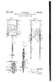
- Fig. 1 is an outline view of a heater suspended from a factory ceiling, with a. jack applied to one end thereof as the preliminary step in my improved method
- Fig. 2 shows the same heater partly lowered at one end with the apparatus employed in practicing the method applied to the supporting rods for the heater
- Fig. 3 is an enlarged detail of the apparatus employed in practicing my invention
- Fig. 4 is a further enlarged sectional detail of the thrust bearing and nut employed in my apparatus.
- I-I represents a heater unit suspended from the ceiling C of a factory or shop by suspension rods R, R according to well-known practice.
- One common method of supporting such units H is to provide angle members a, a extending from one end to the other on both sides of the unit H, which are perforated to receive the rods R, R over the threaded extremities e, e of which are securing nuts 11., n.
- angle members a a extending from one end to the other on both sides of the unit H, which are perforated to receive the rods R, R over the threaded extremities e, e of which are securing nuts 11., n.
- I employ any common type of jack A and a sill S to temporarily jack up one end of the unit H so that the nuts 12, 71. may be removed so as to disengage the one end of the through the openings o in the heater from the supporting rods R, R.
- the jack A is then manipulated so as to allow the end of the heater that is being operated on to be dropped sufiiciently to entirely clear the rods R, R from the angles a, a such as shown in Fig. 2.
- R such apparatus consisting of a coupling l whereby a threaded extension rod 2 is securely connected to each of the rods R (Fig. 3). Obviously, at this time the end of the heater being Worked on is still supported by the jack A.
- the extension rods 2 are passed angle member a and a thrust bearing 3 is passed over the extension rod 2 and held in engagement with the angle member a by a handle nut 4 which traverses the extension rod 2.
- the operator may now manipulate the handle nuts l more or less synchronously so that the -heater will be lowered at each of its four corners approximately simultaneously.
- the extension rods 2 may be of any desired length, depending upon the height of the ceiling C, from which the heater H is suspended; however, should the ceiling be exceptionally high it might be advisable to add a second extension rod to the first extension rod in a manner similar to that in which the first rod 2 is coupled to the suspension rod R.
- a method of moving upwardly or downwardly heavy objects suspended from rods which comprises temporarily propping said object by an. adjustable prop, coupling threaded extension rods to the suspension rods while propped, applying supportin nuts to the extension rods, removing said prop, and successively rotating said supporting nuts to either raise or lower said object.
- the method of lowering heavy objects suspended from threaded rods which comprises temporarily propping said object at one end by REFERENCES CITED an adjustable .prop, releasing said object from the rods at said end, coupling threaded extenzi, fi i z are of record in the sion rods to the suspension rods, applying supporting nuts for the object to the extension rods, 5 UNITED STATES PATENT s removing the prop to p r the Object to rest Number Name Date on said supporting nuts, repea ing ai ep at 1,801,377 Sutliff Apr. 21, 1931 the other end of the object, and succ iv ly 2,089,871 Adams Aug. 10, 1937 withdrawing said supporting nuts, step by step, to permit the object to descend over the exten- 10 sion rods.
Landscapes
- Life Sciences & Earth Sciences (AREA)
- Engineering & Computer Science (AREA)
- Geology (AREA)
- Mechanical Engineering (AREA)
- Structural Engineering (AREA)
- Load-Engaging Elements For Cranes (AREA)
Description
Feb. 6, 1951 H. RESTETSKY METHOD OF RAISING AND LOWERING HEAVY OBJ ECTS Original Filed April 25, 1946 FIG. 2.
INVENTO-R'. HERBERT RESTETSKY ATTORNEY Patented Feb. 6, 1951 METHOD OF RAI SIN G-AN D LOWE-BIN G HEAVY OBJECTS Herbert Restetsky, Maplewood, Mo.
Original application April 23, 1946, Serial No.
664,371. Divided and this application November 1, 1947, Serial No. 783,526
2 Claims.
My invention has relation to improvements in methods of raising and lowering heavy objects. It is common practice in industrial plants to suspend various industrial devices such as heating units, air conditioning units and related equipment from the ceilings by means of suspension rods. Since much of this apparatus is extremely heavy, the placing of the apparatus and removin the same when necessary is an extremely difiicult operation. As far as I am aware this is now done by using a block and tackle and various jacking up'devices.
I have devised an apparatus whereby an entirely new method is evolved which greatly simplifies the operation of installing and removing apparatus of the type referred to; and that furthermore, may be operated by one man.
Of course, the principal object of the present invention is to provide a labor saving device that is simple and efficient and at the same time embodies the necessary safeguards to eliminate the possibility of accident. Other advantages of my invention will be better apparent from a detailed description thereof in connection with the accompanying drawings in which- Fig. 1 is an outline view of a heater suspended from a factory ceiling, with a. jack applied to one end thereof as the preliminary step in my improved method; Fig. 2 shows the same heater partly lowered at one end with the apparatus employed in practicing the method applied to the supporting rods for the heater; Fig. 3 is an enlarged detail of the apparatus employed in practicing my invention; and Fig. 4 is a further enlarged sectional detail of the thrust bearing and nut employed in my apparatus.
Referring to the drawings, I-I represents a heater unit suspended from the ceiling C of a factory or shop by suspension rods R, R according to well-known practice.
One common method of supporting such units H is to provide angle members a, a extending from one end to the other on both sides of the unit H, which are perforated to receive the rods R, R over the threaded extremities e, e of which are securing nuts 11., n. Obviously, when the heater unit H is to be removed it must either be temporarily propped or it must be supported by a block and tackle before the nuts n, n are removed.
In my improved method of raising or lowering the units H, I employ any common type of jack A and a sill S to temporarily jack up one end of the unit H so that the nuts 12, 71. may be removed so as to disengage the one end of the through the openings o in the heater from the supporting rods R, R. The jack A is then manipulated so as to allow the end of the heater that is being operated on to be dropped sufiiciently to entirely clear the rods R, R from the angles a, a such as shown in Fig. 2.
It is now possible for me to apply the apparatus to the rods. R, R such apparatus consisting of a coupling l whereby a threaded extension rod 2 is securely connected to each of the rods R (Fig. 3). Obviously, at this time the end of the heater being Worked on is still supported by the jack A. The extension rods 2 are passed angle member a and a thrust bearing 3 is passed over the extension rod 2 and held in engagement with the angle member a by a handle nut 4 which traverses the extension rod 2. I
When both rods R, R at one end of the unit H have been thus supported on the extension rods 2 the opposite end of the unit H is handled in a like manner, so that the heater unit is finally supported entirely on four thrust bearings, one at each corner of the heater.
The operator may now manipulate the handle nuts l more or less synchronously so that the -heater will be lowered at each of its four corners approximately simultaneously. The extension rods 2 may be of any desired length, depending upon the height of the ceiling C, from which the heater H is suspended; however, should the ceiling be exceptionally high it might be advisable to add a second extension rod to the first extension rod in a manner similar to that in which the first rod 2 is coupled to the suspension rod R.
It should be apparent that in raising a heater unit or equivalent piece of apparatus f-orattachment to suspension rods R, R the operation just described is reversed, that is; instead of lowering the unit H on the rods 2, 2 said unit will be raised thereon by a proper manipulation of the handle nuts 4.
Having described my invention, I claim:
1. A method of moving upwardly or downwardly heavy objects suspended from rods which comprises temporarily propping said object by an. adjustable prop, coupling threaded extension rods to the suspension rods while propped, applying supportin nuts to the extension rods, removing said prop, and successively rotating said supporting nuts to either raise or lower said object.
2. The method of lowering heavy objects suspended from threaded rods, which comprises temporarily propping said object at one end by REFERENCES CITED an adjustable .prop, releasing said object from the rods at said end, coupling threaded extenzi, fi i z are of record in the sion rods to the suspension rods, applying supporting nuts for the object to the extension rods, 5 UNITED STATES PATENT s removing the prop to p r the Object to rest Number Name Date on said supporting nuts, repea ing ai ep at 1,801,377 Sutliff Apr. 21, 1931 the other end of the object, and succ iv ly 2,089,871 Adams Aug. 10, 1937 withdrawing said supporting nuts, step by step, to permit the object to descend over the exten- 10 sion rods.
HERBERT RESTE'ISKY.
Priority Applications (1)
| Application Number | Priority Date | Filing Date | Title |
|---|---|---|---|
| US783526A US2540378A (en) | 1946-04-23 | 1947-11-01 | Method of raising and lowering heavy objects |
Applications Claiming Priority (2)
| Application Number | Priority Date | Filing Date | Title |
|---|---|---|---|
| US66437146A | 1946-04-23 | 1946-04-23 | |
| US783526A US2540378A (en) | 1946-04-23 | 1947-11-01 | Method of raising and lowering heavy objects |
Publications (1)
| Publication Number | Publication Date |
|---|---|
| US2540378A true US2540378A (en) | 1951-02-06 |
Family
ID=27098953
Family Applications (1)
| Application Number | Title | Priority Date | Filing Date |
|---|---|---|---|
| US783526A Expired - Lifetime US2540378A (en) | 1946-04-23 | 1947-11-01 | Method of raising and lowering heavy objects |
Country Status (1)
| Country | Link |
|---|---|
| US (1) | US2540378A (en) |
Cited By (5)
| Publication number | Priority date | Publication date | Assignee | Title |
|---|---|---|---|---|
| US2685423A (en) * | 1951-03-08 | 1954-08-03 | Roe A V & Co Ltd | Bomb and like loading apparatus for aircraft |
| US2692565A (en) * | 1949-09-26 | 1954-10-26 | Crutcher Rolfs Cummings Compan | Pipe conveyer system |
| US2756090A (en) * | 1951-06-19 | 1956-07-24 | Herve A Lessard | Apparatus for handling and storing sheets of material |
| US3047166A (en) * | 1957-12-26 | 1962-07-31 | Gen Electric | Lamp transfer and inverting apparatus |
| US20080056853A1 (en) * | 2006-09-05 | 2008-03-06 | David Willis | Mechanical load bearing device |
Citations (2)
| Publication number | Priority date | Publication date | Assignee | Title |
|---|---|---|---|---|
| US1801377A (en) * | 1928-05-10 | 1931-04-21 | Mueller Co | Meter connection and support |
| US2089871A (en) * | 1937-01-30 | 1937-08-10 | Jacob Stieger | Builder's scaffold |
-
1947
- 1947-11-01 US US783526A patent/US2540378A/en not_active Expired - Lifetime
Patent Citations (2)
| Publication number | Priority date | Publication date | Assignee | Title |
|---|---|---|---|---|
| US1801377A (en) * | 1928-05-10 | 1931-04-21 | Mueller Co | Meter connection and support |
| US2089871A (en) * | 1937-01-30 | 1937-08-10 | Jacob Stieger | Builder's scaffold |
Cited By (6)
| Publication number | Priority date | Publication date | Assignee | Title |
|---|---|---|---|---|
| US2692565A (en) * | 1949-09-26 | 1954-10-26 | Crutcher Rolfs Cummings Compan | Pipe conveyer system |
| US2685423A (en) * | 1951-03-08 | 1954-08-03 | Roe A V & Co Ltd | Bomb and like loading apparatus for aircraft |
| US2756090A (en) * | 1951-06-19 | 1956-07-24 | Herve A Lessard | Apparatus for handling and storing sheets of material |
| US3047166A (en) * | 1957-12-26 | 1962-07-31 | Gen Electric | Lamp transfer and inverting apparatus |
| US20080056853A1 (en) * | 2006-09-05 | 2008-03-06 | David Willis | Mechanical load bearing device |
| AU2010100424B4 (en) * | 2006-09-05 | 2010-08-05 | David Willis | Ceiling Sag Repair |
Similar Documents
| Publication | Publication Date | Title |
|---|---|---|
| US2671697A (en) | Portable shoring | |
| US2540378A (en) | Method of raising and lowering heavy objects | |
| US2463381A (en) | Portable lift | |
| CN207392708U (en) | A kind of Fast Installation scaffold for building | |
| US2136255A (en) | Supporting and elevating means for overhead units | |
| US2060046A (en) | Floor supporting means | |
| US1957184A (en) | Window jack | |
| CN104005564B (en) | The mounting process of the oblique column of a kind of large-scale steel pipe | |
| CN206825323U (en) | A kind of wheeled apparatus for suspension bracket dismounting | |
| CN204209168U (en) | Electric drill fixed mount | |
| CN205500677U (en) | Equipment of crawler crane armed lever, dismantlement auxiliary device | |
| US1538815A (en) | Building apparatus | |
| US2974929A (en) | Panel lifting device | |
| CN206976931U (en) | Supporting wire rack device | |
| CN208166421U (en) | A kind of hanging apparatus of metal plate | |
| CN220833882U (en) | Suitable for H-beam adjustable safety rope suspension device | |
| CN207048286U (en) | Movable expanding is encorbelmented operating platform | |
| CN204773060U (en) | A drilling equipment for concrete structure is drilling upwards | |
| CN215212420U (en) | An energy-saving hanging bar auxiliary operation installation device | |
| JPS6222711Y2 (en) | ||
| CN207566816U (en) | Disk cabinet installs jacking apparatus | |
| DE202007002564U1 (en) | Device for holding and pulling up improperly seated or defective boundary stones, in particular curbs | |
| CN206942292U (en) | Adjustable vertical rod positioning apparatus | |
| CN217518116U (en) | Lifting operation platform for construction of steel structure factory building top layer | |
| CN208394670U (en) | A kind of construction material fast transfer device |