US2539103A - Sofa-bed - Google Patents
Sofa-bed Download PDFInfo
- Publication number
- US2539103A US2539103A US143A US14348A US2539103A US 2539103 A US2539103 A US 2539103A US 143 A US143 A US 143A US 14348 A US14348 A US 14348A US 2539103 A US2539103 A US 2539103A
- Authority
- US
- United States
- Prior art keywords
- box spring
- tracks
- bed
- spring
- portions
- Prior art date
- Legal status (The legal status is an assumption and is not a legal conclusion. Google has not performed a legal analysis and makes no representation as to the accuracy of the status listed.)
- Expired - Lifetime
Links
- 230000000994 depressogenic effect Effects 0.000 description 16
- 125000006850 spacer group Chemical group 0.000 description 14
- 208000020401 Depressive disease Diseases 0.000 description 8
- 238000010276 construction Methods 0.000 description 6
- 230000000694 effects Effects 0.000 description 3
- 230000003028 elevating effect Effects 0.000 description 2
- 230000000717 retained effect Effects 0.000 description 1
- 230000001550 time effect Effects 0.000 description 1
Images

Classifications
-
- A—HUMAN NECESSITIES
- A47—FURNITURE; DOMESTIC ARTICLES OR APPLIANCES; COFFEE MILLS; SPICE MILLS; SUCTION CLEANERS IN GENERAL
- A47C—CHAIRS; SOFAS; BEDS
- A47C17/00—Sofas; Couches; Beds
- A47C17/04—Seating furniture, e.g. sofas, couches, settees, or the like, with movable parts changeable to beds; Chair beds
- A47C17/13—Seating furniture having non-movable backrest changeable to beds by increasing the available seat part, e.g. by drawing seat cushion forward
- A47C17/136—Seating furniture having non-movable backrest changeable to beds by increasing the available seat part, e.g. by drawing seat cushion forward with a single seat cushion
- A47C17/138—Seating furniture having non-movable backrest changeable to beds by increasing the available seat part, e.g. by drawing seat cushion forward with a single seat cushion by lifting or tilting
Definitions
- This invention relates to a convertible sofa-bed, and more particularly to a combination sofa and bed set out in my Patent No. 2,394,969 dated February 12, 1946, and relating to a combination couch and bed.
- the present invention relates to a novel guide rail and supporting rail construction incorporated within the convertible sofa-bed, upon which the box spring is slidably supported by means of a plurality of forwardly and rearwardly arranged pairs oi' roller supports.
- Figure 1 is a perspective view of the convertible sofa-bed.
- Figure 2 is a front elevational view thereof with the mattress and cushions removed for clarity.
- Figure 3 is a bottom plan view thereof.
- Figure 4 is a fragmentary rear elevational View thereof upon a reduced scale.
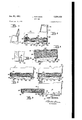
- Figure 5 is a section on line 5 5 of Fig. 2.
- Figure 6 is a fragmentary section illustrating the box spring in its forwardly tipped position.
- Fig. 7 is a fragmentary section illustrating the position of the box spring as slightly moved outwardly from its normal position in Fig. 5.
- Figure 8 is a fragmentary section on line 8--8 of Figure 2.
- Figure 9 is a view similar to Fig. 8 but showingv
- the convertible sofa- Y bed consists of a pair of spaced side arms Il andv I2, to which is secured upright back portion I3,
- a pair of guide rails I5 are suitably secured at lower portions to the inner side walls of side arms I I and I2, and have formed therein in their upper surfaces the longitudinally slotted portions I6.
- a box spring I9 is normally positioned between side arms I i and I2, and is suitably supported upon the guide rails I5, there being a pair of ⁇ rearwardly arranged rollers or roller supports I'i depending from said box spring, as well as a pair of forwardly arranged roller supports I8.
- the pairs of roller supports I1 and I3 cooperatively extend within the longitudinally slotted portions I5 of the side arm supported rails and permit of in and out adjustment of said box spring thereon.
- the box spring I9 shown in the drawings is of4 the conventional construction including stuiling plurality of supporting pillows 22 which are used as indicated when the construction is used as a sofa.
- depressions 32 are formed in the rearward portions of the rails I5, and are adapted to retainingly receive the pair of rearwardly ar ranged roller supports I'I which depend down wardly from and are secured to box spring Zil.I
- Said depressions are adapted to normally retain As shown in Figure l a suitable mattress 2I rests upon box spring I9, and there are also athe box spring in its innermost position, and prevent accidental outward movement thereof upon guide rails I5.
- Secondary depressions 33 are similarly formed adjacent the outer ends of supporting rails I5, and are adapted to cooperatively and retainingly receive said rearwardly arranged roller supports I'I, to limit the outward adjusting movement of the box spring relative to said rails, as illustrated in Figure 9.
- rails I5 terminate in the downwardly inclined portions 3d, upon which roller supports I8 initially rest whereby as viewed in Figures 7 and 8 rollers I8 will easily slide down upon the floor or other support for the sofa-bed.
- roller supports I8 will easily slide down upon the floor or other support for the sofa-bed.
- the rear rollers I1 will ride along the slotted portions I6 of the tracks I5 until they reach depressions 33, which limit the outward movement of said box spring.
- spacer bar 35 is transversely arranged and positioned intermediate guide rails l5, being joined thereto at its ends at points intermediate the ends of said rails, and towards the rear portions thereof.
- a pair of spaced bars 35 are secured tothe rear underside portion of box spring I9', as best illustrated in Figures 3, 5 and 6.
- a spacer rod 31 is mounted upon the underside of said box spring and in spaced relation thereto with its ends being suitably secured through corresponding openings formed within central portions of the spaced bars 35 as at the points 38.
- a pair of spaced levers 39 are mounted upon the underside of box spring I9, with their central e portions pivotally mounted upon spacer rod 3l.
- a second spacer bar l interconnects the rear ends of the spaced levers 39, while the opposite ends of said levers have downwardly extending projections 4I, which in the normal position cooperatively bear against the top longitudinal edge of the spacer 35.
- a pair of iiexible straps 42 have looped portions 113 at their lower ends which extend around spacer bar 4@ which interconnects the levers 39. Said straps extend upwardly around the rear portion of box spring I9, and thence forwardly over the top portion thereof, and terminate in the looped portions lill, permitting grasping thereof.
- depressions 33 are provided within the outer portions of rails or tracks I5, it is contemplated that such depressions may be formed in only one of said rails.
- the box spring may be adjusted outwardly till one of the forwardly arranged rollers I8 is positioned withinV the recess 33 inone of the tracks I5.
- the other forwardly arranged roller is not so limited in its outward movement, and is free to move outwardly down the inclined runout portion 3iA and continue its outward movement.
- the box spring will swing outwardly around the depression 33 in the other rail I5.
- a convertible sofa-bed having spaced side arms, a pair of horizontally arranged tracks joined to the inner lower portions thereof, a box spring positioned between said arms, pairs of forwardly and rearwardly arranged rollers depending from said spring for cooperative engagement with said tracks, there being a depressed portion formed in said tracks at their inner ends to receive said rearwardly arranged rollers for normally retaining the same against outward movement, and manually pivotal lifting means on the underside of said spring engageable with the floor as a fulcrum for elevating said latter rollers from said depressed portions,
- a convertible sofa-bed having spaced side arms, a pair of horizontally arranged tracks joinedA to the inner lower portions thereof, a box spring positioned between said arms, pairs of forwardly and rearwardly arranged rollers depending from said spring for cooperative engagement with said tracks, there being a depressed portion formed in said tracks at their inner ends to retainingly receive said rearwardly arranged rollers, a transverse spacer interconnecting intermediate portions of said tracks, and pivotal lifting means on the under side of said spring engageable with said spacer as a fulcrum for elevating said latter rollers from said depressed portions, permitting outward adjustment of said box spring.
- a convertible sofa-bed having spaced side arms, a pair of horizontally arranged tracks joined to the inner lower portions thereof, a box spring positioned between said arms, pairs of forwardly and rearwardly arranged rollers depending from said spring for cooperative engagement with said tracks, there being a depressed portion formed in said tracks at their inner ends to retainingly receive said rearwardly arranged rollers, a lever pivotally joined to the underside of said box spring, with one end bearing upon the floor, and a strap joined to the other end of said lever extending upwardly around the back of said spring and forwardly upon its top surface, whereby a pull upon said strap will eifect rotary movement of said lever lifting the rearwardly arranged rollers from said depressed portions, and at the same time eifecting outward movement of said box spring upon said tracks.
- a convertible sofa-bed having spaced side arms, a pair of horizontally arranged tracks joined to the inner lower portions thereof, a box spring positioned between said arms, pairs of forwardly and rearwardly arranged rollers depending from said spring for cooperative engagement with said tracks, there being a depressed portion formed in said tracks at their inner ends to retainingly receive said rearwardly arranged rollers, a transverse spacer interconnecting said tracks, a lever pivotally joined to the underside of said spring, with one end bearing cooperatively against said spacer as a fulcrum, and a strap joined to the other end of said lever extending upwardly around the back of said spring and forwardly upon its top surface, whereby a pull upon said strap will effect rotary movement of said lever lifting the rearwardly arranged rollers from said depressed portion, at the same time effecting outward movement of said box spring upon said tracks.
- a convertible sofa-bed having spaced side arms, a pair of horizontally arranged tracks joined to the inner lower portions thereof, a box spring positioned between' said arms, pairs of forwardly and rearwardly arranged rollers depending from said spring for cooperative engagement with said tracks, there being a depressed portion formed in said tracks at their inner ends to retainingly receive said rearwardly arranged rollers, a pair of spaced levers pivotally joined to the underside of said box spring, with their ends bearing upon the floor, and a pair of spaced straps joined to the other ends of said levers, extending upwardly around the back of said box spring and forwardly upon its top surface, whereby a pull upon said straps will effect rotary movement of said levers lifting the rearwardly arranged rollers from said depressed por- 6 tions and at the same time effecting outward movement of said box spring upon said tracks.
- a convertible sofa-bed having spaced side arms, a pair of horizontally arrangedtracks joined to the inner lower portions thereof, a box spring positioned between said arms, pairs of forwardly and rearwardly arranged rollers depending from said spring for engagement with said tracks, there being a depressed portion formed in said tracks at their inner ends to retainingly receive said rearwardly arranged rollers, a pair of spaced levers pivotally joined to the underside of said box spring with their ends bearing upon the floor, a spacer interconnecting their other ends, and a pair of spaced straps joined to said spacer, extending upwardly around the back of said box spring and forwardly upon its top surface, whereby a pull upon said straps will effect a lifting of said rearwardly arranged rollers from said depressed portions, and at the same time effect outward movement of said box spring upon said tracks.
- a convertible sofa-bed having spaced side arms, a pair of horizontally arranged tracks joined to the inner lower portions thereof, a box spring positioned between said arms, pairs of forwardly and rearwardly arranged rollers depending from said spring for engagement with said tracks, there being a depressed portion formed in said tracks at their inner ends to retainingly receive said rearwardly arranged rollers, a lever pivotally joined to the underside of said box spring, with one end bearing upon the floor, a strap joined to the other end of said lever extending upwardly around the back of said spring and forwardly upon its top surface, and a strap guiding and retaining loop secured at its ends to the forward top portions of said box spring, through which the free ends of said strap extend.
Landscapes
- Health & Medical Sciences (AREA)
- General Health & Medical Sciences (AREA)
- Nursing (AREA)
- Special Chairs (AREA)
Description
Jan. 23, 1951 L. ROBINSON 2,539,103
SOFA BED Filed Jan. 2, 1948 2 Sheets-Shea?l l IIHI Jan. 239 1951 RQBlNSON 2,539,103
SOFA BED Filed Jan. 2, 1948 2 Sheets-Sheet 2 *IIIIIII'I'I'A VIII.
:@ 9 BY Lows RomsoN.
ATTORNEY.
Patented Jan. 23, 1951 UNITED STATES PTENT GFFICE 7 Claims.
This invention relates to a convertible sofa-bed, and more particularly to a combination sofa and bed set out in my Patent No. 2,394,969 dated February 12, 1946, and relating to a combination couch and bed.
Still more particularly the present invention relates to a novel guide rail and supporting rail construction incorporated Within the convertible sofa-bed, upon which the box spring is slidably supported by means of a plurality of forwardly and rearwardly arranged pairs oi' roller supports.
It is therefore the principal object of this invention to provide in a sofa-bed oi the type specied, a pair of box spring guiding and supporting rails secured to the interior portions of the side walls, or side arms thereof, upon which the box spring is supported for in and out adjustment thereon.
It is the further object of this invention to provide depressed portions adjacent the inner ends of said rails adapted to retainingly receive the rearwardly arranged roller supports of the boX spring to prevent accidental outward adjustment thereof relative to said rails.
Itis the further object of thisinvention to provide a pivotal lifting device upon the under side of said box spring whereby said rearwardly arranged rollers may be lifted from said depressed portions, and at the same time said box spring may be moved outwardly upon said rails.
It is the still further object of this invention to provide depressed portions adjacent the outer ends of said rails which are adapted to retainingly receive said rearwardly arranged rollers to limit the outward adjustment of said box spring.
In the sofa-bed construction above specified it is desirable that the box spring be moved outwardly upon its supports to permit remaking of the bed; and it is therefore the object of this invention to provide a novel means of simplified construction whereby the box spring may be readily rolled outwardly for this purpose.
These and other objects will be seen from the following specication and claims in conjunction with the appended drawings in which:
Figure 1 is a perspective view of the convertible sofa-bed.
Figure 2 is a front elevational view thereof with the mattress and cushions removed for clarity.
Figure 3 is a bottom plan view thereof.
Figure 4 is a fragmentary rear elevational View thereof upon a reduced scale.
Figure 5 is a section on line 5 5 of Fig. 2.
Figure 6 is a fragmentary section illustrating the box spring in its forwardly tipped position.
Fig. 7 is a fragmentary section illustrating the position of the box spring as slightly moved outwardly from its normal position in Fig. 5.
Figure 8 is a fragmentary section on line 8--8 of Figure 2.
Figure 9 is a view similar to Fig. 8 but showingv Referring to the drawings, the convertible sofa- Y bed consists of a pair of spaced side arms Il andv I2, to which is secured upright back portion I3,
by means of a plurality of studs and wing nuts I4, 'y
as illustrated in Figures 3, 4 and 5. This construction by way of illustration permits of easy dismantling of the sofa-bed, as desired, for shipping.
A pair of guide rails I5 are suitably secured at lower portions to the inner side walls of side arms I I and I2, and have formed therein in their upper surfaces the longitudinally slotted portions I6.
A box spring I9 is normally positioned between side arms I i and I2, and is suitably supported upon the guide rails I5, there being a pair of` rearwardly arranged rollers or roller supports I'i depending from said box spring, as well as a pair of forwardly arranged roller supports I8.
The pairs of roller supports I1 and I3 cooperatively extend within the longitudinally slotted portions I5 of the side arm supported rails and permit of in and out adjustment of said box spring thereon.
The box spring I9 shown in the drawings is of4 the conventional construction including stuiling plurality of supporting pillows 22 which are used as indicated when the construction is used as a sofa.
Referring to Figures 5 through l0 it will be seen that depressions 32 are formed in the rearward portions of the rails I5, and are adapted to retainingly receive the pair of rearwardly ar ranged roller supports I'I which depend down wardly from and are secured to box spring Zil.I
Said depressions are adapted to normally retain As shown in Figure l a suitable mattress 2I rests upon box spring I9, and there are also athe box spring in its innermost position, and prevent accidental outward movement thereof upon guide rails I5.
It will be noted that rails I5 terminate in the downwardly inclined portions 3d, upon which roller supports I8 initially rest whereby as viewed in Figures 7 and 8 rollers I8 will easily slide down upon the floor or other support for the sofa-bed. As the box spring is rolled outwardly the rear rollers I1 will ride along the slotted portions I6 of the tracks I5 until they reach depressions 33, which limit the outward movement of said box spring.
A pair of spaced bars 35 are secured tothe rear underside portion of box spring I9', as best illustrated in Figures 3, 5 and 6. A spacer rod 31 is mounted upon the underside of said box spring and in spaced relation thereto with its ends being suitably secured through corresponding openings formed within central portions of the spaced bars 35 as at the points 38.
A pair of spaced levers 39 are mounted upon the underside of box spring I9, with their central e portions pivotally mounted upon spacer rod 3l.
A second spacer bar l interconnects the rear ends of the spaced levers 39, while the opposite ends of said levers have downwardly extending projections 4I, which in the normal position cooperatively bear against the top longitudinal edge of the spacer 35.
A pair of iiexible straps 42, have looped portions 113 at their lower ends which extend around spacer bar 4@ which interconnects the levers 39. Said straps extend upwardly around the rear portion of box spring I9, and thence forwardly over the top portion thereof, and terminate in the looped portions lill, permitting grasping thereof.
The free ends of straps 42 slidably and guidingly extend through the looped retainers 45' positioned forwardly of said box spring, and with their ends secured thereto, whereby the looped ends of the straps i2 are normally retained in the position shown in Figure 5.
Operation To remove the box spring from its innermost position it is necessary to manually grasp the loops 44 of both straps 42, pulling upon the same, and causing upward pivotal movement of the spaced levers 39, whose free ends are adapted to bear against the top surface of spacer 35.
' As viewed in Figures 3, 5 and 6 the downwardly extending portions lil of said'levers cooperatively bear against the top of transverse spacer bar 35 which acts as a fulcrum for said levers.
As viewed in Figure 6 a manual pull or outward thrust upon the straps l2 will cause a pivota-l movement of the levers 39 in a counterclockwise direction, and a corresponding upward pivotal movement of the rear portion of box spring Thus it is seen that rollers I7 will be elevated out of the depressions 32 in guide rails I5, and at the same time due to the outward thrust upon said straps, said box spring will be moved outwardly upon guide rails I5 in the manner illustrated in Figures 7 and 9.
Normally to remake, or to make the bed, it is desirable that said box spring be moved outwardly from the position shown in Figure 8. While it is not necessary that said box` spring be moved out to the position shown in Figure 9 this is desirable. It is seen that the secondary depressions 33 in said guide rails are adapted to limit the outward movement of box spring I9 as shown in Figure 9, and this isV the position normally employed for remaking the bed.
While the above specification refers to the elements I5 as the supporting rails for the roller members which depend from a box spring, the claims hereafter set out refer to said elements as tracks in describing' the same.
While it is above specified that depressions 33 are provided within the outer portions of rails or tracks I5, it is contemplated that such depressions may be formed in only one of said rails. Thus the box spring may be adjusted outwardly till one of the forwardly arranged rollers I8 is positioned withinV the recess 33 inone of the tracks I5. However, the other forwardly arranged roller is not so limited in its outward movement, and is free to move outwardly down the inclined runout portion 3iA and continue its outward movement. Thus the box spring will swing outwardly around the depression 33 in the other rail I5.
Thus making of the bed is facilitated in permitting one to walk behind the box spring at one edge thereof.
Having described my invention reference should now be had to the claims which follow for determining the scope thereof.
I claim:
1. In a convertible sofa-bed having spaced side arms, a pair of horizontally arranged tracks joined to the inner lower portions thereof, a box spring positioned between said arms, pairs of forwardly and rearwardly arranged rollers depending from said spring for cooperative engagement with said tracks, there being a depressed portion formed in said tracks at their inner ends to receive said rearwardly arranged rollers for normally retaining the same against outward movement, and manually pivotal lifting means on the underside of said spring engageable with the floor as a fulcrum for elevating said latter rollers from said depressed portions,
permitting outward adjustment of said spring.
2. In a convertible sofa-bed having spaced side arms, a pair of horizontally arranged tracks joinedA to the inner lower portions thereof, a box spring positioned between said arms, pairs of forwardly and rearwardly arranged rollers depending from said spring for cooperative engagement with said tracks, there being a depressed portion formed in said tracks at their inner ends to retainingly receive said rearwardly arranged rollers, a transverse spacer interconnecting intermediate portions of said tracks, and pivotal lifting means on the under side of said spring engageable with said spacer as a fulcrum for elevating said latter rollers from said depressed portions, permitting outward adjustment of said box spring.
3. In a convertible sofa-bed having spaced side arms, a pair of horizontally arranged tracks joined to the inner lower portions thereof, a box spring positioned between said arms, pairs of forwardly and rearwardly arranged rollers depending from said spring for cooperative engagement with said tracks, there being a depressed portion formed in said tracks at their inner ends to retainingly receive said rearwardly arranged rollers, a lever pivotally joined to the underside of said box spring, with one end bearing upon the floor, and a strap joined to the other end of said lever extending upwardly around the back of said spring and forwardly upon its top surface, whereby a pull upon said strap will eifect rotary movement of said lever lifting the rearwardly arranged rollers from said depressed portions, and at the same time eifecting outward movement of said box spring upon said tracks.
4. In a convertible sofa-bed having spaced side arms, a pair of horizontally arranged tracks joined to the inner lower portions thereof, a box spring positioned between said arms, pairs of forwardly and rearwardly arranged rollers depending from said spring for cooperative engagement with said tracks, there being a depressed portion formed in said tracks at their inner ends to retainingly receive said rearwardly arranged rollers, a transverse spacer interconnecting said tracks, a lever pivotally joined to the underside of said spring, with one end bearing cooperatively against said spacer as a fulcrum, and a strap joined to the other end of said lever extending upwardly around the back of said spring and forwardly upon its top surface, whereby a pull upon said strap will effect rotary movement of said lever lifting the rearwardly arranged rollers from said depressed portion, at the same time effecting outward movement of said box spring upon said tracks.
5. In a convertible sofa-bed having spaced side arms, a pair of horizontally arranged tracks joined to the inner lower portions thereof, a box spring positioned between' said arms, pairs of forwardly and rearwardly arranged rollers depending from said spring for cooperative engagement with said tracks, there being a depressed portion formed in said tracks at their inner ends to retainingly receive said rearwardly arranged rollers, a pair of spaced levers pivotally joined to the underside of said box spring, with their ends bearing upon the floor, and a pair of spaced straps joined to the other ends of said levers, extending upwardly around the back of said box spring and forwardly upon its top surface, whereby a pull upon said straps will effect rotary movement of said levers lifting the rearwardly arranged rollers from said depressed por- 6 tions and at the same time effecting outward movement of said box spring upon said tracks.
6. In a convertible sofa-bed having spaced side arms, a pair of horizontally arrangedtracks joined to the inner lower portions thereof, a box spring positioned between said arms, pairs of forwardly and rearwardly arranged rollers depending from said spring for engagement with said tracks, there being a depressed portion formed in said tracks at their inner ends to retainingly receive said rearwardly arranged rollers, a pair of spaced levers pivotally joined to the underside of said box spring with their ends bearing upon the floor, a spacer interconnecting their other ends, and a pair of spaced straps joined to said spacer, extending upwardly around the back of said box spring and forwardly upon its top surface, whereby a pull upon said straps will effect a lifting of said rearwardly arranged rollers from said depressed portions, and at the same time effect outward movement of said box spring upon said tracks.
7. In a convertible sofa-bed having spaced side arms, a pair of horizontally arranged tracks joined to the inner lower portions thereof, a box spring positioned between said arms, pairs of forwardly and rearwardly arranged rollers depending from said spring for engagement with said tracks, there being a depressed portion formed in said tracks at their inner ends to retainingly receive said rearwardly arranged rollers, a lever pivotally joined to the underside of said box spring, with one end bearing upon the floor, a strap joined to the other end of said lever extending upwardly around the back of said spring and forwardly upon its top surface, and a strap guiding and retaining loop secured at its ends to the forward top portions of said box spring, through which the free ends of said strap extend.
LOUIS ROBINSON.
REFERENCES CITED The following references are of record in the file of this patent:
UNITED STATES PATENTS Number Name Date 473,984 White May 3, 1892 '755,089 Wersel Mar. 22, 1904 1,027,007 Sisbower May 21, 1912 1,080,217 Hoey Dec. 2, 1913
Priority Applications (1)
| Application Number | Priority Date | Filing Date | Title |
|---|---|---|---|
| US143A US2539103A (en) | 1948-01-02 | 1948-01-02 | Sofa-bed |
Applications Claiming Priority (1)
| Application Number | Priority Date | Filing Date | Title |
|---|---|---|---|
| US143A US2539103A (en) | 1948-01-02 | 1948-01-02 | Sofa-bed |
Publications (1)
| Publication Number | Publication Date |
|---|---|
| US2539103A true US2539103A (en) | 1951-01-23 |
Family
ID=21690119
Family Applications (1)
| Application Number | Title | Priority Date | Filing Date |
|---|---|---|---|
| US143A Expired - Lifetime US2539103A (en) | 1948-01-02 | 1948-01-02 | Sofa-bed |
Country Status (1)
| Country | Link |
|---|---|
| US (1) | US2539103A (en) |
Cited By (8)
| Publication number | Priority date | Publication date | Assignee | Title |
|---|---|---|---|---|
| US2694207A (en) * | 1949-10-10 | 1954-11-16 | Lendrum A Maceachron | Bed and housing means for same |
| US2702864A (en) * | 1951-04-04 | 1955-02-22 | Texaco Development Corp | Measuring device |
| US2738520A (en) * | 1953-03-13 | 1956-03-20 | Murphy Door Bed Company Inc | Combined sofa and bed |
| US3069698A (en) * | 1960-03-14 | 1962-12-25 | Globe Bedding Company Ltd | Convertible chesterfield and bed unit |
| US3106072A (en) * | 1961-10-03 | 1963-10-08 | Muffly Glenn | Refrigerator-freezer |
| US3132781A (en) * | 1961-05-31 | 1964-05-12 | Frank G Poczatek | Collapsible carrier device |
| US3175228A (en) * | 1962-12-03 | 1965-03-30 | Elwood S Quarngesser | Sofa bed structure |
| AT396735B (en) * | 1990-08-13 | 1993-11-25 | Papst Erich | Seat which can be converted into a couch |
Citations (4)
| Publication number | Priority date | Publication date | Assignee | Title |
|---|---|---|---|---|
| US473984A (en) * | 1892-05-03 | Combined folding-bed case and wardrobe | ||
| US755089A (en) * | 1902-12-03 | 1904-03-22 | Frank B Wersel Jr | Sofa-bed. |
| US1027007A (en) * | 1911-09-06 | 1912-05-21 | New York Couch Bed Company | Couch-bed. |
| US1080217A (en) * | 1913-10-06 | 1913-12-02 | John Hoey | Folding couch. |
-
1948
- 1948-01-02 US US143A patent/US2539103A/en not_active Expired - Lifetime
Patent Citations (4)
| Publication number | Priority date | Publication date | Assignee | Title |
|---|---|---|---|---|
| US473984A (en) * | 1892-05-03 | Combined folding-bed case and wardrobe | ||
| US755089A (en) * | 1902-12-03 | 1904-03-22 | Frank B Wersel Jr | Sofa-bed. |
| US1027007A (en) * | 1911-09-06 | 1912-05-21 | New York Couch Bed Company | Couch-bed. |
| US1080217A (en) * | 1913-10-06 | 1913-12-02 | John Hoey | Folding couch. |
Cited By (9)
| Publication number | Priority date | Publication date | Assignee | Title |
|---|---|---|---|---|
| US2694207A (en) * | 1949-10-10 | 1954-11-16 | Lendrum A Maceachron | Bed and housing means for same |
| US2702864A (en) * | 1951-04-04 | 1955-02-22 | Texaco Development Corp | Measuring device |
| US2738520A (en) * | 1953-03-13 | 1956-03-20 | Murphy Door Bed Company Inc | Combined sofa and bed |
| US3069698A (en) * | 1960-03-14 | 1962-12-25 | Globe Bedding Company Ltd | Convertible chesterfield and bed unit |
| US3132781A (en) * | 1961-05-31 | 1964-05-12 | Frank G Poczatek | Collapsible carrier device |
| US3106072A (en) * | 1961-10-03 | 1963-10-08 | Muffly Glenn | Refrigerator-freezer |
| US3175228A (en) * | 1962-12-03 | 1965-03-30 | Elwood S Quarngesser | Sofa bed structure |
| AT396735B (en) * | 1990-08-13 | 1993-11-25 | Papst Erich | Seat which can be converted into a couch |
| AT399642B (en) * | 1990-08-13 | 1995-06-26 | Papst Erich | Seat which can be converted into a couch |
Similar Documents
| Publication | Publication Date | Title |
|---|---|---|
| US3003160A (en) | Foldable bed frame-bed to contour chair | |
| US2217426A (en) | Convertible furniture structure | |
| US2539103A (en) | Sofa-bed | |
| US2328411A (en) | Convertible couch structure | |
| US3135551A (en) | Deck-chair with automatic backrest locking device | |
| US2570401A (en) | Sofa bed | |
| US3858254A (en) | All-way rest | |
| US2709478A (en) | Baby bed and chair combination | |
| US2283000A (en) | Glider | |
| US1702955A (en) | Chair | |
| US3110909A (en) | Combination twin bed and sofa | |
| DK145053B (en) | SITTING FURNITURE WITH LOOSE SEAT CUSHION AND ADJUSTED TO BE CHANGED TO A BED | |
| US2024170A (en) | Combination chair and cot | |
| US2081374A (en) | Duo-bed couch | |
| US2126588A (en) | Davenport bed | |
| US2240204A (en) | Chair bed | |
| US2317243A (en) | Baby swing | |
| US2248603A (en) | Combined chair and bed | |
| US1710821A (en) | Wheel chair | |
| US2136830A (en) | Convertible bed couch | |
| US2260079A (en) | Bed chair | |
| US1982930A (en) | Convertible seat and bed | |
| US2534176A (en) | Combined sofa seat and bed | |
| US2352375A (en) | Sofa bed | |
| US2712655A (en) | Bed settees |