US2518924A - Stem making method and apparatus - Google Patents
Stem making method and apparatus Download PDFInfo
- Publication number
- US2518924A US2518924A US555729A US55572944A US2518924A US 2518924 A US2518924 A US 2518924A US 555729 A US555729 A US 555729A US 55572944 A US55572944 A US 55572944A US 2518924 A US2518924 A US 2518924A
- Authority
- US
- United States
- Prior art keywords
- tube
- glass
- flare
- exhaust tube
- wires
- Prior art date
- Legal status (The legal status is an assumption and is not a legal conclusion. Google has not performed a legal analysis and makes no representation as to the accuracy of the status listed.)
- Expired - Lifetime
Links
- 238000000034 method Methods 0.000 title description 14
- 239000011521 glass Substances 0.000 description 55
- 238000007789 sealing Methods 0.000 description 15
- 238000010438 heat treatment Methods 0.000 description 11
- 239000007787 solid Substances 0.000 description 9
- 239000011324 bead Substances 0.000 description 5
- 229910001018 Cast iron Inorganic materials 0.000 description 4
- 238000001816 cooling Methods 0.000 description 4
- 238000004519 manufacturing process Methods 0.000 description 4
- 230000000994 depressogenic effect Effects 0.000 description 3
- 238000005336 cracking Methods 0.000 description 2
- 230000004927 fusion Effects 0.000 description 2
- 239000006060 molten glass Substances 0.000 description 2
- 230000000284 resting effect Effects 0.000 description 2
- 229910001369 Brass Inorganic materials 0.000 description 1
- OKTJSMMVPCPJKN-UHFFFAOYSA-N Carbon Chemical compound [C] OKTJSMMVPCPJKN-UHFFFAOYSA-N 0.000 description 1
- 241000518994 Conta Species 0.000 description 1
- 241000784713 Cupido Species 0.000 description 1
- 101100163433 Drosophila melanogaster armi gene Proteins 0.000 description 1
- XEEYBQQBJWHFJM-UHFFFAOYSA-N Iron Chemical compound [Fe] XEEYBQQBJWHFJM-UHFFFAOYSA-N 0.000 description 1
- 101150081243 STA1 gene Proteins 0.000 description 1
- 101150057833 THEG gene Proteins 0.000 description 1
- 230000015572 biosynthetic process Effects 0.000 description 1
- 239000010951 brass Substances 0.000 description 1
- 229910052799 carbon Inorganic materials 0.000 description 1
- 238000000576 coating method Methods 0.000 description 1
- 230000008602 contraction Effects 0.000 description 1
- 235000019628 coolness Nutrition 0.000 description 1
- 238000009826 distribution Methods 0.000 description 1
- 230000000694 effects Effects 0.000 description 1
- 230000002708 enhancing effect Effects 0.000 description 1
- 239000002184 metal Substances 0.000 description 1
- 229910052751 metal Inorganic materials 0.000 description 1
- 238000000465 moulding Methods 0.000 description 1
- 108090000623 proteins and genes Proteins 0.000 description 1
- 230000005855 radiation Effects 0.000 description 1
Images


Classifications
-
- H—ELECTRICITY
- H01—ELECTRIC ELEMENTS
- H01J—ELECTRIC DISCHARGE TUBES OR DISCHARGE LAMPS
- H01J9/00—Apparatus or processes specially adapted for the manufacture, installation, removal, maintenance of electric discharge tubes, discharge lamps, or parts thereof; Recovery of material from discharge tubes or lamps
- H01J9/24—Manufacture or joining of vessels, leading-in conductors or bases
- H01J9/32—Sealing leading-in conductors
-
- H—ELECTRICITY
- H01—ELECTRIC ELEMENTS
- H01K—ELECTRIC INCANDESCENT LAMPS
- H01K3/00—Apparatus or processes adapted to the manufacture, installing, removal, or maintenance of incandescent lamps or parts thereof
- H01K3/20—Sealing-in wires directly into the envelope
Definitions
- Myiinve'ntionirelatesiin/lgerieralto lead-infseals for-enclosed electricalfdevicesfsuch ras evacuated Y electronic discharge. 'devices and electric lamps,
- iriventionfis 'particularly applicable to ⁇ a the lead-'inlwires are-sealed "in a circular 4arrangementethroug'h a unitary glass 'stem struetureccomprising fa glass flare ⁇ 'centrallyfj-oined to an rexhausttabulatiom In fthemianufature'ioa ⁇ electric .incandescent lamps and rsimilarl electrical idevices, it is ⁇ customa-ry, during the sealing of the stem into the bulbgffto fwork::. :the softened glass ⁇ at the seal;
- arrdfapparatus foremanufacturinga ste-m forielectricialzdevices: which is f or? relatively short overalll height and ⁇ which willreadily seal-t the cylindrical :neck ofaiglass bulb-without cracking,
- Another Objectis ⁇ -izo ⁇ provide. a methodV of makn ing ⁇ such' seals without mechanically molding ⁇ the fused-joint in which the'iead-'in *wiresare' sealed,
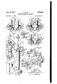
- FIG. 1 is a diagrammatic planviewof:apparatus comprising my invention fier manufacturing stems; ⁇ ontharing-seal type, only the head at stationff'being shovvzr loaded .Witlrthe' 'various stem parts; ⁇ ig. ⁇ :2 is' ai. vertical sectio'rr f tlf'rreughV onef diathe.
- the 'various-iV stem partis"arerstfassembled Vin proper sealing? relation Withfthe several Alead-in Wiresf'crcularly arrangedrin aco'nned annular spaceb'etweenair enlargedforiflared Wall portion at the'lupperend yof the'exhausttubeandthecylindrical Wall por# ticnfoi alfglassliiarel orrstemtub'e'which is preferFJ ably'zplacedin.anfinverted position Vand whichv concentricallyvencloses lthe exhaust" tulcieenlargeeY ment. With the stem parts thus positlonedjthe first meltedaround the lead-in Wires. Thenfthe inner? ⁇ glass V.vvall 'ofrthe assemblyv (i*e., the en;
- the ⁇ apparatus aclcordingiito' the invention comprises a turret ori carrier member l provided 'With'a plurality (12" in ythis case) o'f heads" 2 located 'at uniformlyVTV space'cl intervals areund'fth'e periphery of 'the turret..1
- The-turret Is is supported env a vertical Shaft" 3 3 journalled in the machine bed 4 and is intermittently rotated in a counterclockwise direction to successively index or advance the heads 2 to each of a plurality (24 in this case) of work stations A to Y.
- the indexing means for the turret I may be of any well known type, such as that illustrated and described in U. S. Patent 1,742,153, Stiles et al.
- Each of the heads 2 comprises a vertically extending hollow spindle journalled in a bearing 6 on a bracket 1 which is fasten-ed to the turret I and projects from its periphery.
- the spindle 5 remains stationary While it is Vpositioned at the loading stations A to F but is rotated at the remaining stations G to Y by means of a moving belt 8 which engages With a pulley 9 fastened to the lower end of the spindle.
- the spindle 5 is provided with suitable means for supporting and maintaining the various stem parts in proper sealing relation to one -another Vduring the seal-forming operation.
- theV spindle 5 is provided with av cast-iron cap IB fitting over the spindle head II and having its top surface I2 provided with a centrally located seat I3 for supporting a glass exhaust tube I4.
- the said exhaust tube is formed at one end with anenlarged portion I5 of relatively short length and providing a shoulder I6 which is adapted to rest on the seat I3. Heat is conducted away fromv the shoulder portion I6 of theexhaust tub'ethrough the seat I3 during the sealing operations so that the said shoulder portionretains its shape.
- the exhaust tube I4 is positioned iin the spindle with its enlarged end I5 uppermost and with its'remainder'or stem portion. I1 extending down into the hollow interior or bore I8 of the spindle '5, the said bore I8 being just large enough to freely receive the said stem portion of the exhaust tube while centering it in the'. spindle.
- the cap I9 and the spindle head I lare further provided with a circularlv arranged group of vertically extending holes I9 for receiving and vertil cally positioning a desired number of lead-in wires 20 at spaced points around and immediately outward of the enlarged upper end I 5 of the exhaust tube I4.
- Y fourteen of such lead-in wires 29 are shown, each of said wires comprising a three-part lead consisting of inner and outer leads 2 I, 22 (Fig. 3) butt-welded to an intermediate press or seal lead 23, as indicated at 24 and 25 respectively.
- the lead-in Wires -2IJ may be provided with glass coatings or beads 23' fused to andv around the seal lead portions 23 and the upper weld knots 24 of the wires, as shown in dotted lines in Fig. l1.
- the lead-in wires 20 are supported in proper vertical position relative to the enlarged upper end I5 of the exhaust tube, with the upper or inner Weld knots' 24 of the wires located alongside the said exhaust tube enlargementA I5, by means of a stop or positioning collar 26 which is fastened to the spindle 5 below the spindle head I I and is vertically adjustable on the spindle.
- the lead-in wires 29 are inserted and moved down through the holes I9 in the spindle cap I0 and head I I until their lower ends project out beyond theV lower ends of the holes I9 in the spindle head II and engage the stop collar 26.
- a cast iron plate or ring 21 Positioned a short distance above the spindle cap I0 and vertically aligned with the spindle 5 is a cast iron plate or ring 21 for positioning and supporting a glass nare or stem tube 28 concentric with the enlarged upper end I5 of the exhaus/,t tube I4.
- the said flare 2.8 consists of a.
- the neck portion 29 ofthe nare 28 is just large enough in diameter to iit over and closely surround the circularly arranged group of lead-in wires 28 positioned in the spindle holes I9.
- the flare support ring 21 is fastened to and supported by a pair of diametrically opposite posts 3
- the flare support ring 21 is provided with a central opening 33 concentric with the spindle bore I8 and the circularly arranged group of lead-in wire holes I9, and just large enough to receive the neck portion 29 of the flare 28 so as to center it on the spindle.
- the flare 28 is positioned'in an inverted position on the support ring 21 with its flanged end uppermost and the flange 39 resting on the ring.
- the vertlcal'position of the are support ring 21r relative to the spindle cap I0 is so fixed, by proper adjustment of the collar 32 on the spindle cap I9, as to position the neck portion 29 'of the flare directly opposite or alongside the enlarged upper end I5 of the exhaust tube so as to surround the said tube end portion.
- Yof large size flares 28 for instance those having an internal diameter of around one inch or more, it is desirable to keep the lower end of the flare neck 29 up off the spindle cap I 9, as shown, since with these parts in contact the are might crack because.
- the Various stem parts comprising the exhaust tube I4, the lead-in Wires 29 and the flare 28, are loaded into their proper sealing position in the head 2' (as shown in Fig. 2) while the head is positioned at the loading stations A to F, the complete loading of the head usually being performed at stations A and B.
- the loaded head 2 is then carried by the turret I to idle station G Where the spindle pulley 9 engages the moving belt 8 t0 initiate rotation of the spindle 5.
- the head 2 is then su"- cessively indexed in turn to each of three preheating 'stations H, J and K where soft gas fires 34 from burners 35 located at said stations are directed against the cylindrical portion 29 of the glass are 28 (as shown in Fig. 2) to preheat,
- the head 2 is then successively indexed to each of five similar sealingflre stations L to P inclusive at each of which is located two diametrically opposite pairs of gas burners 36 which direct hard pin-point gas res 31 (Fig. 3) horizontally against the neck portion 29 of the flare 28.
- These fires 31 cause the glass of the flare neck 29 to gradually become molten and to gather up around the lead-in wires 20 in the manner shown in Fig. 3.
- the enlarged upper end I5 of the exhaust tube I4 receives enough heat by radiation from the fused flare neck 29 to become plastic and capable of deformation.
- the head 2 is next indexed to the glass puddling station Q where the enlarged upper end I5 of the exhaust tube is preferably further heated by a pair of opposed sharppointed gas fires 38 (Fig. 4) directed downwardly at an angle against the said uppper end of the exhaust tube, the glass of the flare neck 29 meanamarga wrilefibeng maintained f-:init's fn-lolten.'.@condition i f infer-:opposed: gasires Sissirriilar to 7those emitir-ingdthe* dwell ⁇ of the head zat :station 1Q.
- tlreipl'a'sti upper fen'di *ofithe feirlrau'st tube is expmded ⁇ horizontally outward against Sthell'eadini'fwires 2.a 'fand :intoifintirnate conta'ctwithwthe' molten'fgiass ofthe nare lne'ckf29ziby meansfof 'au suitable :ipuddling device '139 located atzsaid sta-1 tion.
- The4 horizontal fand vertical :movements ⁇ -fof thenpuddlingl rod 3Q may 'abe automatically-effected by meansfof a vertically; extendingfbpe atingirodidl to the upper Vendl ofiwhioh: is fastened a horizontal armf'zll 'which h'airri'esthe ⁇ v ⁇ ddling rod G0 in a position directly over the .'Espindleei.Lv of the head Ziatstati'on '.Q. i
- The: 'operating rod 41 isi-'supported inIasleevebearingf 43 which 'is 'fase tenedto a bracket lilfsecmfed to thefbedwofitlie f machine.
- rocker 4armfi carriesa l on'the-periphery of adiseeamf @meente on l main'driveshat l'oithemae ine.l r"'lfeifcam "5&1 isffrmed with-anelevated portionfa d"e ⁇ Vpressed'-porthm*"'l.
- the shaft 68 vcarlriesfanotherarmg A which is ⁇ connected by-'a 'ver ⁇ :tioallin'k Ito one endiof a rocker larm 'li pivotally ymountedonalstudshaft l2.
- the other endf of'the ⁇ rocker arm ll carries a roller 13 which rides on'theper-iphery offa disc cam 14 mounted Y on fthe ⁇ rnain.”olrive shaft 55 and provided witha depressed portion 'and a'slightly elevated portion 16.
- the head 2 is successively indexed tozstations R and S where sharp-pointed fires 31 and 38, like ⁇ those at station Q, heat the are neck 29 and the upper enlarged end I5 of the ,exhaust tube into a solid mass of molten glass as shown 5 in Fig. 5.
- the stem may be considered completed at this stage and may be used in the form shown in said Fig. 5. However, I prefer to further work the seal and modify its shape to that shown in Figs. 6 and 15.
- the push up of the exhaust tube I4, during the index of the head 2 from stations S to T, may be conveniently produced by a push rod 84 which 25 is reciprocably mounted in the bore I8 of the spindle ⁇ 5 and which engages with an inclined cam track 85 (Figs. l and 10) mounted on the bed 4 of the'machine.
- the push rod 84 is provided with a transversely extending pin 89 which 3l) projects into, and normally rests on the bottom of a vertically elongated slot 31 in the spindle 5 to thereby support the push rod in the spindle.
- VThe upper end 88 of the push rod S4 is normally flare 28 remains in its original position down on 45 theflare support ring 21, rather than being lifted up off the ring by the exhaust tube, by reason of Y the fact vthat the hot ange portion 39 of the flare 28 sticks to a slight degree to the cast iron ilare support ring 21.
- the head 2 is then indexed in turn through the remaining idle stations U to X, inclusive, where the completed seal is allowed to cool in the surrounding atmosphere so'as to permit its removal from the head 2 by an operator at the Yunloading station Y.
- the difference in the cooling and contraction rates of the glass and the cast iron flare support ring 21 ordinarily 6o causes the glass flange portion 39 of the completed stem, which theretofore had been stuck to the said ring, to break away from the ring 21 and-thus free the stem for removal from the head.
- the glass flare or stem tube 28 is mounted on the spindle 5 .in a position the re- 75 verse from that which it occupies in the previously described method, i. e., with its flange 39 lowermost and resting on the upper surface I2 of the spindle cap I0.
- the upper surface I2 of the spindle cap I0 is formed with an annular recess 9
- the said upper surface I2 is also j ⁇ provided with a raised frusta-conical seat 92 for engaging the underside of the stem tube flange 3U to further support and center the stem tube 23 on the spindle.
- the cylindrical Wall or neck portion 29 of the flare or stem tube 28 is first preheated by directing thereagainst a soft gas fire like the fire 34 shown in Fig. 2.v Thereafter, the said neck portion 29 of the rotating flare 28 is subjected to intensive heating by a pair of hard Ipin-point sealing fires 93, 94 to thereby melt the said neck portion 29 down and around the lead-in wires 2D in the manner illustrated in Fig. 12.
- Gas fire 93 is directed approximately horizontally against the upper region of the cylindrical flare neck 29 while gas fire 94 is directed approximately horizontally against the lower region of the said flare neck at the zone where the seal is ultimately formed as shown in Fig. 13.
- the heat radiated by the fused glass of the flare 28 serves to heat the enlarged upper end I5 of the exhaust tube sufficiently to soften it so as to be capable of deformation.
- the puddling rod 49 is inserted within the enlarged upper end of the exhaust tube and is then moved laterally into outward pressure engagement with the plastic enlarged wall portion I 5 of the rotating exhaust tube to thereby expand and press the said wall portion I5, progressively around its entire circumference, against the lead-in wires 29 and into adhering contact with the fused o neck 29 of the flare 28.
- the puddling rod 40 is held against the plastic wall I5 of the exhaust tube during at least one complete revolution of the spindle 5 so as to expand'the said wall I 5v completely around its full circular extent.
- the glass around the said wires is then further heated by gas res 94 and 9S until it becomes a solid molten mass and sags down onto the flat top 91 of the frusto-conical flare seat 92, as shown in Fig. 13.
- the gas re 94 heats the glass at the outer side of the lead-in wires 29 while the gas re 96 is directed against the glass at the inner side of the said wires.
- the fire 96 is preferably directed downwardly at a relatively steep angle so as to clear the upper ends of the lead-in wires 20.
- Apparatus for making stems of the ringseal type comprising a head having means for supporting a stem assembly comprising a glass flare tube, glass exhaust tube and a plurality of lead-in Wires in sealing relation with the flare supporting a ste1n a sser nbly- ⁇ cr'pr-isin'gTA alV glass 'iflai'e ⁇ tibe", glass exhaus'ttube and' a plurality of ylealdifinvr Wiresfhsealig relationE vviththeae tube concenftr'ially surrundirigan end"V f the exhaust tube and tHelead-in Wi'resexte'rdirfg longitudinally"between said tubeV through he ariz'ular4 space therebetween, means located* ad- -jacfen't-v saidfhead for'- fusing" the nare" tube arid the lsaid eridQo'f the-ex
- Apparatus-ihr' making: stems-of' the ringse'al type-comprising Ya carrier member provided W'ltha pluralityfof Heads each e'oihprisingl a -rotatable spindle' arranged to supporta stern sembly comprising-a glass nare" tube, quaint haust tube 'and a plurality oi leadin Wires-1in "sealing relation with thlexh'aust tubel ext vertically vandi" the flarev tllibeV concentricall roundiriglthe uflz'perend ofthe' exhausttub withv the lead-in Wires'- exten"diner: ver
- Apparatus" forY makingv stems ofl the Yring- Asealjtype comprising a' carrier ⁇ -mniber prvideii with a" plurality of he'ads'j each'comprisih'g a 'rotatableJv spindle arrangedtois'u'pport a stem as- 'sernbly comprisingfa gia "flaifffftuber glass' exhaast tube” an'd' a plurality of) leadin iiir'es-v ⁇ in sealing relation with the exhaust tube extending vertically and the ilare tube concentrically surrounding the upper end of the exhaust tube and with the lead-in wires extending vertically through the annular space between the said tubes, means for intermittently indexing said carrier member to successively index said heads to a plurality of work stations, means at one of said stations for fusing the iiare tube around the leadin wires, means at a succeeding station for heating
- Apparatus for making stems of the ring-seal type comprising a carrier member provided with a plurality of heads each comprising a rotatable spindle arranged to support a stem assembly comprising a glass 4flare tube, glass exhaust tube and a plurality of lead-in wires in sealing relation with the exhaust tube extending vertically and the flare tube concentrically surrounding the upper end of the exhaust tube and with the leadin wires extending vertically through the annular space between the said tubes, means for intermittently indexing said carrier member to suctube end to press it outwardly against the leadin wires and the fused flare tube during rota tion of said spindle, means at a subsequent station for fusing together the flare tube and the upper end of the exhaust tube into a solid molten mass, and means for subsequently moving the exhaust tube upward a small amount to work and redistribute the glass at the inner Yside of the seal.
- Apparatus for making stems of the ring- Vseal type comprising a vertically disposed spindle having openings for receiving and vertically supporting a glass exhaust tube and a plurality of lead-in wires in sealing relation with the lead-in ⁇ wires spaced about and alongside the upper end of the exhaust tube, means carried by the spindle for supporting a glass nare tube concentrically about the upper end of the exhaust tube and around the said lead-in wires with its flared end uppermost, means located adjacent said spindle for heating and fusing the contiguous wall portions of the are tube and the said exhaust tube,
- Y a puddling rod associated with said spindle and movable into and thence laterally within the f upper end of the exhaust tube to press the wall Athereof laterally outward against the lead-in wires and the flare tube, and means comprising a push rod Yvertically movable within said spindle to move the exhaust tube upward and thus effect a working and redistribution of the glass at the inner side of the seal.
- the method of making stems -for sealed electrical devices which comprises assembling a glass iiare tube concentrically around an enlarged end of a glass exhaust tube with a plurality of lead-in wires extending longitudinally between said tubes, fusing a portion of the flare tube around the lead-in wires and heating the enlarged end of the exhaust tube to a plastic condition, expanding the said exhaust tube end against the lead-in wires and into contact with the flare tube while the latter is in a fused condition, fusing together the flare tube and the said exhaust tube end into a solid molten mass, and then displacing the exhaust tube a small distance longitudinally inward of the are to redistribute the glass at theY inner side of the seal.
- the method of making stems for sealed electrical devices which comprises assembling a glass nare tube concentrically around an enlarged upper end of a vertically disposed glass/exhaust tube with a plurality of lead-in wires extending vertically through the annular space between said tubes, fusing a portion of the flare tube around the lead-in wires and heating the said enlarged end of the exhaust tube to a plastic condition, expanding the said exhaust tube end against the lead-in wires and into contact with the nare tube while the latter is in a fused condition, fusing together the flare tube and the said exhaust tube end into a solid molten mass, and then displacing the exhaust tube a small distance vertically upward relative to the nare tube to re-distribute the glass at the inner side of the seal.
Landscapes
- Engineering & Computer Science (AREA)
- Manufacturing & Machinery (AREA)
- Joining Of Glass To Other Materials (AREA)
Description
Aug. 15,1950' E. NIMES Y. 2,515,924
STEM MAKING METHOD AND -APPARA'I'l-JS DW W His Attorneg- Aug. 15, 1950 E. NlLEs 2,518,924
Y STEM MAKING METHOD AND APPARATUS Y Filed sept. 15',v 1944 4 sheets-sheet 2 Fig?) Fig@ 20 g 35 2 f.
\ /f f/O ZO f 3260 um l '111111111'.
Inventor: EveVeJc Nilesb9 His A'knfneg lug.`l5, 1950 la. NILES 2,513,924
STEM uAKING METHOD AND'APPARATUS l y nvnr: vi l Evere Niles bg W His Attorng Aug- 15, 1950 E. NlLEs 2,518,924
STEM MAKING METHOD AND APPARATUS Filed Sept. 15, 1944 4 Sheets-Sheet 4 Fig 11 20W /7720 325i I 92 2al I :1 m/emor: z i Ever-@H Nues ,Patented Aug. 15, 1950 lSTEM MAKING METHOD AND APPARATUS Everett iNiles,` :Willoughby, Ohio, assigner? to Gene `eral lElectric Company, a corporationoNeW f York Application'september 15, 1944, Serial No. 555,729
112 Claims.v
Myiinve'ntionirelatesiin/lgerieralto lead-infseals for-enclosed =electricalfdevicesfsuch ras evacuated Y electronic discharge. 'devices and electric lamps,
and morexparticularlyto-a method and apparatus fortliefmamifacturefof such seals,
The.: iriventionfis 'particularly applicable to` a the lead-'inlwires are-sealed "in a circular 4arrangementethroug'h a unitary glass 'stem struetureccomprising fa glass flare `'centrallyfj-oined to an rexhausttabulatiom In fthemianufature'ioa` electric .incandescent lamps and rsimilarl electrical idevices, it is` customa-ry, during the sealing of the stem into the bulbgffto fwork::. :the softened glass `at the seal;
such-as by aipull-down nice/ementref the stem, to ltherebylliminate sharp 'angles- Vbetween lthe stem-and bulbandisolfacilfitate thefformation of a substantially .strainffree andtheref'ore mechani'c'allystrong.-seal. :Suena relative displace-A ment!` of the vst'em 'fand vbulb lis.' net' permissible; however, intlre case oficertai-nrelectrical devices suchfas cathodefraytubesfwherein both the stem and` thebulb-,neck carry separate electrical elements;.Whiclfi` `must lbe ,precisely positioned with respect to one another and which must befrnain# tainedainf-such precise'relajtienlduring the sealing-iri-opeiaticn Y One'. object'oi my invention is to `provide :a
method arrdfapparatus: foremanufacturinga ste-m forielectricialzdevices: which is f or? relatively short overalll height and `which willreadily seal-t the cylindrical :neck ofaiglass bulb-without cracking,
Another Objectis `-izo` provide. a methodV of makn ing` such' seals without mechanically molding `the fused-joint in which the'iead-'in *wiresare' sealed,
Another objectof Ymy' rinventioniis to provide a` method'andff apparatusior'manufacturing stem' f of :the'fringeal type Whiclrvwill readily iusiom seal-.tti the glassrneck "of-2' abulb,,to form a me cha'nicallystrongseal, Y-vv'ithout the need of dis-- placing; the stern-and` the bulb'zneck relative toV one anotherduringi the: sealing opera-tion.
Further obaiectsfiandadvantages of` my inventionwillappearrmm the-lfoliawing'description of a speciesxzthereoii andfromfthe accompanying drawings in `ivhielizziv l Fig. 1 is a diagrammatic planviewof:apparatus comprising my invention fier manufacturing stems;` ontharing-seal type, only the head at stationff'being shovvzr loaded .Witlrthe' 'various stem parts;` ig.` :2 is' ai. vertical sectio'rr f tlf'rreughV onef diathe. 'heads Voffthe said:"apparatus,` the head thefvari'ouslstem parts 'inf their asm :shawn pesiticned eatxxtlre: prensa-ting sta# semblefd'sealing position Yin the head; Figs-3 tuI 1,
6 arefragmentarysectional vi'eW's showing suce cessive steps @comprising my improved sealingzy methodyFigf'lisa perspective view-of theseale.
puddling'mechanism -at-stationQ and one ofthej heads pesitionedithereatg' Figis a plan'viewfof the `said. iseal-puddlingmechanism at` station' Q; z Fig. kEl is an elevation of the seal-puddling' mecha-1- nism `at'` istation /Qr and `the operating meansiv therefor; Fig.' `10 i isfan elevation of the" exhaust tube fpusheup devicel at' station 'Twith a cooper#- atingihead shown inrsection at saidst'ation; `Figs.l
11 to 13 arefragme'ntary'sectionalvievvsfslfioiiling'siV successive stepstof :a modified' sealing 4vmethod a'cf cordingftomywinvention; Fig. 1411s anrelevation;
partly-broken away,- of :the stem" produced by *the modied fmetho'cll.of.Figs. l11to :13; 'and Fig. :15 is .anaelevatiomfpartly broken away, of tliezfstemprodue'edfbyfthe'preferred method'ef Figs-3 to6.-
In accordance `with the invention, the 'various-iV stem partis"arerstfassembled Vin proper sealing? relation Withfthe several Alead-in Wiresf'crcularly arrangedrin aco'nned annular spaceb'etweenair enlargedforiflared Wall portion at the'lupperend yof the'exhausttubeandthecylindrical Wall por# ticnfoi alfglassliiarel orrstemtub'e'which is preferFJ ably'zplacedin.anfinverted position Vand whichv concentricallyvencloses lthe exhaust" tulcieenlargeeY ment. With the stem parts thus positlonedjthe first meltedaround the lead-in Wires. Thenfthe inner?` glass V.vvall 'ofrthe assemblyv (i*e., the en;
larged upper end portion: fof the leXhai-ist tube?,
which hasbeen 'heated'tothe-:softeningpeint-'by `.radiationvof heat vfroml the :are' tube `or^by addi;
tional heating 4meansvsuch as gas rires directed thereagainst, 4is then expanded yradially youtwardf4 against-the lead-in `Wires and into'adhering con" tactA with :the 'plasticL flare Wall by means Yof Va suitable puddling'tool- The joint thus terrified"4 is then tlrorouglily'heated to--form a solid `mass of m'olten'glass.L Thereafter, inac'cordancewitlr my preferred process; a slight upward,I movement is imparted tothefexhaust tubetto Work and re"- `distributethe A:glass 'at 'the inner side of the sea'l'y and pro'ducea :comparatively large mass of 'glass at tlie inner' side of theY lead-in Wires which?H completely imbeds the upper YWeld knots' of the said Wires to a considerable depth.
Referring'to 'the' drawings, the `apparatus aclcordingiito' the invention comprises a turret ori carrier member l provided 'With'a plurality (12" in ythis case) o'f heads" 2 located 'at uniformlyVTV space'cl intervals areund'fth'e periphery of 'the turret..1 The-turret Is is supported env a vertical Shaft" 3 3 journalled in the machine bed 4 and is intermittently rotated in a counterclockwise direction to successively index or advance the heads 2 to each of a plurality (24 in this case) of work stations A to Y. The indexing means for the turret I may be of any well known type, such as that illustrated and described in U. S. Patent 1,742,153, Stiles et al.
Each of the heads 2 comprises a vertically extending hollow spindle journalled in a bearing 6 on a bracket 1 which is fasten-ed to the turret I and projects from its periphery. The spindle 5 remains stationary While it is Vpositioned at the loading stations A to F but is rotated at the remaining stations G to Y by means of a moving belt 8 which engages With a pulley 9 fastened to the lower end of the spindle. Y l
At its upper end, the spindle 5 is provided with suitable means for supporting and maintaining the various stem parts in proper sealing relation to one -another Vduring the seal-forming operation. For this purpose, theV spindle 5 is provided with av cast-iron cap IB fitting over the spindle head II and having its top surface I2 provided with a centrally located seat I3 for supporting a glass exhaust tube I4. The said exhaust tube is formed at one end with anenlarged portion I5 of relatively short length and providing a shoulder I6 which is adapted to rest on the seat I3. Heat is conducted away fromv the shoulder portion I6 of theexhaust tub'ethrough the seat I3 during the sealing operations so that the said shoulder portionretains its shape. The exhaust tube I4 is positioned iin the spindle with its enlarged end I5 uppermost and with its'remainder'or stem portion. I1 extending down into the hollow interior or bore I8 of the spindle '5, the said bore I8 being just large enough to freely receive the said stem portion of the exhaust tube while centering it in the'. spindle.
The cap I9 and the spindle head I lare further provided with a circularlv arranged group of vertically extending holes I9 for receiving and vertil cally positioning a desired number of lead-in wires 20 at spaced points around and immediately outward of the enlarged upper end I 5 of the exhaust tube I4. Y In the particular case illustrated, fourteen of such lead-in wires 29 are shown, each of said wires comprising a three-part lead consisting of inner and outer leads 2 I, 22 (Fig. 3) butt-welded to an intermediate press or seal lead 23, as indicated at 24 and 25 respectively. If desired, the lead-in Wires -2IJ may be provided with glass coatings or beads 23' fused to andv around the seal lead portions 23 and the upper weld knots 24 of the wires, as shown in dotted lines in Fig. l1. The lead-in wires 20 are supported in proper vertical position relative to the enlarged upper end I5 of the exhaust tube, with the upper or inner Weld knots' 24 of the wires located alongside the said exhaust tube enlargementA I5, by means of a stop or positioning collar 26 which is fastened to the spindle 5 below the spindle head I I and is vertically adjustable on the spindle. The lead-in wires 29 are inserted and moved down through the holes I9 in the spindle cap I0 and head I I until their lower ends project out beyond theV lower ends of the holes I9 in the spindle head II and engage the stop collar 26.
Positioned a short distance above the spindle cap I0 and vertically aligned with the spindle 5 is a cast iron plate or ring 21 for positioning and supporting a glass nare or stem tube 28 concentric with the enlarged upper end I5 of the exhaus/,t tube I4. The said flare 2.8 consists of a.
short cylindrical neck or collar portion 29 approximating the length of the enlarged upper end I5 of the exhaust tube I4 and having a flange 30 extending -outwardly from one end thereof. The neck portion 29 ofthe nare 28 is just large enough in diameter to iit over and closely surround the circularly arranged group of lead-in wires 28 positioned in the spindle holes I9. The flare support ring 21 is fastened to and supported by a pair of diametrically opposite posts 3| fastened to a collar 32 which is secured to, but vertically adjustable on the spindle cap I0. The flare support ring 21 is provided with a central opening 33 concentric with the spindle bore I8 and the circularly arranged group of lead-in wire holes I9, and just large enough to receive the neck portion 29 of the flare 28 so as to center it on the spindle. The flare 28 is positioned'in an inverted position on the support ring 21 with its flanged end uppermost and the flange 39 resting on the ring. The vertlcal'position of the are support ring 21r relative to the spindle cap I0 is so fixed, by proper adjustment of the collar 32 on the spindle cap I9, as to position the neck portion 29 'of the flare directly opposite or alongside the enlarged upper end I5 of the exhaust tube so as to surround the said tube end portion. InV the case Yof large size flares 28, for instance those having an internal diameter of around one inch or more, it is desirable to keep the lower end of the flare neck 29 up off the spindle cap I 9, as shown, since with these parts in contact the are might crack because.
of excessive conduction of heat away from the flare by the cap I9.
In the operation of the apparatus according to the invention, the Various stem parts, comprising the exhaust tube I4, the lead-in Wires 29 and the flare 28, are loaded into their proper sealing position in the head 2' (as shown in Fig. 2) while the head is positioned at the loading stations A to F, the complete loading of the head usually being performed at stations A and B. The loaded head 2 is then carried by the turret I to idle station G Where the spindle pulley 9 engages the moving belt 8 t0 initiate rotation of the spindle 5.
From idle station G the head 2 is then su"- cessively indexed in turn to each of three preheating 'stations H, J and K where soft gas fires 34 from burners 35 located at said stations are directed against the cylindrical portion 29 of the glass are 28 (as shown in Fig. 2) to preheat,
the flare and so prevent it from cracking.
Following the preheating of the glass flare 28 at stations H, J, and K, the head 2 is then successively indexed to each of five similar sealingflre stations L to P inclusive at each of which is located two diametrically opposite pairs of gas burners 36 which direct hard pin-point gas res 31 (Fig. 3) horizontally against the neck portion 29 of the flare 28. These lires 31 cause the glass of the flare neck 29 to gradually become molten and to gather up around the lead-in wires 20 in the manner shown in Fig. 3. At the same time, the enlarged upper end I5 of the exhaust tube I4 receives enough heat by radiation from the fused flare neck 29 to become plastic and capable of deformation.
From station P, the head 2 is next indexed to the glass puddling station Q where the enlarged upper end I5 of the exhaust tube is preferably further heated by a pair of opposed sharppointed gas fires 38 (Fig. 4) directed downwardly at an angle against the said uppper end of the exhaust tube, the glass of the flare neck 29 meanamarga wrilefibeng maintained f-:init's fn-lolten.'.@condition i f infer-:opposed: gasires Sissirriilar to 7those emitir-ingdthe* dwell` of the head zat :station 1Q. tlreipl'a'sti upper fen'di *ofithe feirlrau'st tube is expmded` horizontally outward against Sthell'eadini'fwires 2.a 'fand :intoifintirnate conta'ctwithwthe' molten'fgiass ofthe nare lne'ckf29ziby meansfof 'au suitable :ipuddling device '139 located atzsaid sta-1 tion. In accordance with the invention. ythe said puddnngedeviee :se compri-ses:faevertitally posed'ipuddlihgx rod ille FigsflY-Q) `'which is 'rst lowereddnto fthe :enlarged upper end 2| 5 f of the i rotating exhaust vtiibe vl M fand'ais ff'thensrzmoved 5 laterally into L outward .1.pressurei;.engagenentwithxy the fs'ai'dfupper end of.the=eiihaust-tu`oe, asshown inflFigf.y 1 4.-'v Thedcontimied' rotation-1.6i fathefexrhast :tube I4, while the :rod 4i) eis-.thus pressed outwardly-.against'ethe plastierwallwi' of the 'ei:rm haust tube, thus causes the'sai-d-walltoibefpressed y outwardly progressivelyaroundits'entireoirounre` ferenrze so `as gto limbed the 'leadeimwiresfzyandstiekftol the imolte'n VneokfZS of the are'fZSf" The 12;) puddlin'g-rod 4% is made A 'offf a -suitabie rnaterial=,v such as i brass for 'f Carbon, .whchv `will noti;perma-nrw nentlyl adhere to thessotenediglass; :andthe ga? f fires r38 a are 1rlooated .on oppositefsdes of? the rod sofas not to impingethereagainst. if
The4 horizontal fand vertical :movements `-fof thenpuddlingl rod 3Q may 'abe automatically-effected by meansfof a vertically; extendingfbpe atingirodidl to the upper Vendl ofiwhioh: is fastened a horizontal armf'zll 'which h'airri'esthe`v` ddling rod G0 in a position directly over the .'Espindleei.Lv of the head Ziatstati'on '.Q. i The: 'operating rod 41 isi-'supported inIasleevebearingf 43 which 'is 'fase tenedto a bracket lilfsecmfed to thefbedwofitlie f machine. Y For Je'ffe'ctingV the vertiealu movements `of the pudling rod Ml, the-fflowerlen'd :of theioperating; rod-'P4' iv Vis oonhecte'dto a moreori lesslhoraontally: extending arm-'- 4.5 (Fig.y V9) through-1 averticalllink-f 46"'having 'both a pivotal andiswivel'onnectionf'i 545 wit thefoperatihg rod. The arm-", is fastened.' onffalioriz'ontal shaft-48 "supported inea' b'ear'irigf.Y (riot'fsh'own') -rnounted ont e"mahi'r'i'e'bed1 .Alb
extending thereirornfin a direetien more' or le opposite"ftofthea1-m @i5 islfeoineoftd l'o'y-'aiv'ertioal i link 5&1 5to-y one end offarokei'farmI pivot'ally mounted Ona stndshaf 52 the rocker 4armficarriesa l on'the-periphery of adiseeamf @meente on l main'driveshat l'oithemae ine.l r"'lfeifcam "5&1 isffrmed with-anelevated portionfa d"e` Vpressed'-porthm*"'l. The ielevated.*portionI {i5-fof the cam Elliits and holds "the fpud'dling rod E'f in l itsfeleva'ted or inoperative position( as sh'ovvnfo in`fll.lines` i'nfFig. V9) ljust'befreand during'the i index movement of the tu'i"`1"et`il "sothat the said rod lisup out vof the path of 'inoveneitffthe lead-in wires 2U andthe other parts of th'e stem assemblyas thelatter-is'indexed to and away? fromstation Q; The depressed.pertionnlofther cam 55 allows? the operatingfrodr-iyarmwsizfand y puddling rod4` 11%v `to vmove :dov-Jn,Joff-A their own weightfto the low'er or operative;positionrot i the' 'T70 puddling rod l(as showninidottedvlinesiiniig. il) i as vsoon asia head- 2Yreaohes-station andwhii'efr it is positioned' thereat. The lowered epositionof 1 the'puddlinerodfa ois determined .by ine-engager ating rod f4 I :with the upper fend `59 :of fthe sleeve puddlingrodto 4'into and out ofupressure .engagea mentwi-ththeplastio side wallofrtlieiexhaust tuoe enlargement 5f-,the operating .rod lll is provided.
with l' aihorizont'ally .extending arm .or I bracket .G0
carryinganupstanding iingeror .pin ,E l. `The pinVV zontally reciprocable slide 83to .thereby move thel f pinfvand thus .rotate the operating rod ill l clock'- wise 'as'vie'wedin:l5ig..8)v so as to move the puddling-ro'd 4511.? laterally lout of engagement withthe enlargedupperlend Eb'o the eXhaus-ttube` andreturfn iti-toits normal position more or less een?.
tered with respect `tothefspindle 5. as shown inlV fuillin'esin Figs. 8and39. 'The slide 53,13 slidably` mounted 'in la fguide block illsecured 'to the machine " bed 13,7 andlfitfcarries a pin SEUwhich is? receive/dTwithin the `space `'ioetween the two arms at thebifurcated end of a leverlarm 6'! which is fastened-.to a horizontal shaft 68 supported on the `machine bed 4. The shaft 68 vcarlriesfanotherarmg Awhich is` connected by-'a 'ver` :tioallin'k Ito one endiof a rocker larm 'li pivotally ymountedonalstudshaft l2. The other endf of'the` rocker arm ll carries a roller 13 which rides on'theper-iphery offa disc cam 14 mounted Y on fthe `rnain."olrive shaft 55 and provided witha depressed portion 'and a'slightly elevated portion 16. The elevated portion A'Iii of the cam effeots'theareturn movement of the puddl'ing rod im f to lits 'inoperative or centered postionrelative f. raised Tto its elevated position'by the cani 54. -TlieY depressed portion 'i5 o the cam 'lli allows the puddli-ng rod fllffto A'be moved laterally .from v.its centered V"postion'into' outward pressure engagement withth'e plastic:upper end i5 of' the .exeV i haust tube just after the said rod El moves down 1 toitsv lowered-position oilovingithe arrival-of a head ZHatfstation Q. Thefdepressed portion' 75.01A
withdrawn or'moved-laterally away fronithe pin 1.165 bythe aetion'of atensioncoil spring 'Eiconn nectedb'etween the rocker arm H and the bed or i terclockwse (Fig. 8) so as to swing `thepuddling rod-"d `laterally from its centered Vposition into engagement vwith the plastic upper end vl5 of' the exhaust tubeuf The slight oonnterclookwise .ro-4 x tational movement of the operating rod M: `1neoe`s`sary`to move thepuddling rodli againstlthe exhaust tnbewall portion l5 is 'effectedbythe action- `of la "more or "lessi 'horizontally disposed tensionrcoiil spring "IS 'whichv is connected between posts'lg ifextending'from twoarm'srS and 8| Lone of wh-lola ICarm18) Vis fastened to.a collar 8235ecured to thelupper end 'of the sleeve bearing 43 andthe: other oneeof which (armi) is fastened.. toftliefsto'p collar` 58 ion-fthe operating rodl 4i. The
adaptedlto engage/.the other or stationary arrnl 'toftherebylimitthe extent of lateral movement of thelpu'ddling rodfll away from its normal oentered position by thespring 58 and so determine`v `th'e `amountfoffexpansion ofthe plastic upper end wall lfof the. exhaust tube-'bythe puddlin'g rod.
Eoilowin'glthe'glass Ipuddlingfoperationwat sta- 7 tion Q, the head 2 is successively indexed tozstations R and S where sharp-pointed fires 31 and 38, like `those at station Q, heat the are neck 29 and the upper enlarged end I5 of the ,exhaust tube into a solid mass of molten glass as shown 5 in Fig. 5. AIf desired, the stem may be considered completed at this stage and may be used in the form shown in said Fig. 5. However, I prefer to further work the seal and modify its shape to that shown in Figs. 6 and 15.
'I'he form of seal shown in Figs. 6 and 15 is obtained by moving the exhaust tube I4 upward a slight distance relative toY the are 28, during the index of head 2 to the next station T, to work and redistribute the molten glass at the l5 inner side of the seal. This push up of the exhaust tube assures the presence of'a comparatively large amount of glass at the inner Side of the lead-in Wires 29 and completely imbedding the upper weld knots 24 thereof to a considerable 20 depth, such a glass distribution enhancing the@ formation of a strong and hermetically tight seal.
The push up of the exhaust tube I4, during the index of the head 2 from stations S to T, may be conveniently produced by a push rod 84 which 25 is reciprocably mounted in the bore I8 of the spindle`5 and which engages with an inclined cam track 85 (Figs. l and 10) mounted on the bed 4 of the'machine. The push rod 84 is provided with a transversely extending pin 89 which 3l) projects into, and normally rests on the bottom of a vertically elongated slot 31 in the spindle 5 to thereby support the push rod in the spindle.
VThe upper end 88 of the push rod S4 is normally flare 28 remains in its original position down on 45 theflare support ring 21, rather than being lifted up off the ring by the exhaust tube, by reason of Y the fact vthat the hot ange portion 39 of the flare 28 sticks to a slight degree to the cast iron ilare support ring 21.
Following the glass working and redistributing operations at station T, the head 2 is then indexed in turn through the remaining idle stations U to X, inclusive, where the completed seal is allowed to cool in the surrounding atmosphere so'as to permit its removal from the head 2 by an operator at the Yunloading station Y. During the cooling of the completed stem, the difference in the cooling and contraction rates of the glass and the cast iron flare support ring 21 ordinarily 6o causes the glass flange portion 39 of the completed stem, which theretofore had been stuck to the said ring, to break away from the ring 21 and-thus free the stem for removal from the head. However, in the case of smaller size seals, such as those having a flare neck diameter of less than one inch or so, it may be necessary to accelerate the cooling of the glass stem, as by air jets 99 directed thereagainst at one or more of the cool-- ing stations U to X (preferably station W), in orderto separate the glass flange 39 of the stem fromrthe metal support ring 21.
In the modified seal-forming method illustrated in Figs. 11 toy 13, the glass flare or stem tube 28 is mounted on the spindle 5 .in a position the re- 75 verse from that which it occupies in the previously described method, i. e., with its flange 39 lowermost and resting on the upper surface I2 of the spindle cap I0. For this purpose, the upper surface I2 of the spindle cap I0 is formed with an annular recess 9| for receiving the flange 39 of the flare or stem tube 28 and centering the latter on the spindle 5. The said upper surface I2 is also j `provided with a raised frusta-conical seat 92 for engaging the underside of the stem tube flange 3U to further support and center the stem tube 23 on the spindle.
With the exhaust tube I4, lead-in Wires 29 and flare or stem tube 29 mounted in proper sealing relation on the rotatable spindle 5 in the manner shown in Fig. 11, the cylindrical Wall or neck portion 29 of the flare or stem tube 28 is first preheated by directing thereagainst a soft gas fire like the fire 34 shown in Fig. 2.v Thereafter, the said neck portion 29 of the rotating flare 28 is subjected to intensive heating by a pair of hard Ipin-point sealing fires 93, 94 to thereby melt the said neck portion 29 down and around the lead-in wires 2D in the manner illustrated in Fig. 12. Gas fire 93 is directed approximately horizontally against the upper region of the cylindrical flare neck 29 while gas fire 94 is directed approximately horizontally against the lower region of the said flare neck at the zone where the seal is ultimately formed as shown in Fig. 13. During the heating and fusion of the flare neck 29 by the gas res 93, 94, the heat radiated by the fused glass of the flare 28 serves to heat the enlarged upper end I5 of the exhaust tube sufficiently to soften it so as to be capable of deformation.
When the heating and fusion of the fiare 28 has progressed to the pointwhere the upper end of the flare neck 29 has melted down approximately to the level of the upper end or rim 95 of the exhaust tubeA I4 as shown in Fig. 12, the puddling rod 49 is inserted within the enlarged upper end of the exhaust tube and is then moved laterally into outward pressure engagement with the plastic enlarged wall portion I 5 of the rotating exhaust tube to thereby expand and press the said wall portion I5, progressively around its entire circumference, against the lead-in wires 29 and into adhering contact with the fused o neck 29 of the flare 28. The puddling rod 40 is held against the plastic wall I5 of the exhaust tube during at least one complete revolution of the spindle 5 so as to expand'the said wall I 5v completely around its full circular extent.
After the enlarged upper end I5 of the exhaust tube has been thus joined with the fused are neck 29 so as to imbed the lead-in Wires 20, the glass around the said wires is then further heated by gas res 94 and 9S until it becomes a solid molten mass and sags down onto the flat top 91 of the frusto-conical flare seat 92, as shown in Fig. 13. The gas re 94 heats the glass at the outer side of the lead-in wires 29 while the gas re 96 is directed against the glass at the inner side of the said wires. As shown, the fire 96 is preferably directed downwardly at a relatively steep angle so as to clear the upper ends of the lead-in wires 20.
When the fused glass around the lead-in wires' 2U has thus sagged down onto the top 91 of the are seat 92, the heating of the glass is discontinued and the stem allowed to cool, after which it'may be removed from the head 2. As shown in Fig. 14, the completed seal thus formed is characterized by a relatively thick band of Letters Patent-'dfi the UnitedStates is:
1 Themethod lolfjrrlaiung stemsfr sealed deetrcal devices which@ comprises vassenbling"'a"g` le, 'ss
'ilare'tube c onc'e'itricallyv around' ein enla ged 'tubular' ed Oria-- gla'SsPexhausttube viiitha 111,-n rality dfV leadin Wires e'x'ter'idiifig` longitudinally between the flaretbe' and'theenlaged eridff thele'xhaust tubeffusing`v a-^ prtion" o f the flare tube/around the lead-in/tvires'and heating' the sajde'd' Otf the e"`X].' 1'al.1stl tube' to a" plastic'A cor1- dition, l expanding the plas-ticA exhaust' Ytube end against the leadingin' vs'lires*and*into4 contact vwith the; fused portion of thefiar'e byappl'ying pressure laterally outtvardagainst a limited area lif the inner'vi/all of'thesaidtubeendandtheriee progressively around (the periphery of said-viali,
. v"-fusin'gtogether'theflare tube and theisaid'exhaust tube end into asolifd molten mass",y arid'tl'en v'displacing the *exhaust tube Aasmallf distance longitudinally intvard f the flare While` the saidi f massi is still `plastic to redistribute and"` thicken thglass'-vatthe 'inner side f theiseal.H
2. The method f making stems forsealed tube and the's' dexha'usttbe end into a solid tube a small distance longitudinallyinward' of the flarewlrilethe saidfmass' is still plastic to redistribute and thicken the glass at the-inner `side'of A'the seal.
The 4m@theirorn'falzing "stfffs'ifor sensuele@- tricalfdevices whien'coiprfises assembling! glass `tubular end 6i' aglas's xhausttube With-a pluralityi of ,glass-beaded lead-in Wires extending longitudinally tl'riigl'A the annular spaceV between the flare' tube andthe enlarged endfrif-"the exhaust tube andhavng' theirU glass beads"V locatedv Within the's'aidvspace,`l fusing au portion Aoifthe flare tube around they lead-in wiresfand the glass beads thereon-and heating tlieLsaid-end .f'the exhaust tube to a .plastic conditiongf expanding the saidexhaust tubeend againstthe `lead-in Wires and the glassbeads thereon land against the flare tube While the saidY glass beads and flare tubear'efr'a'afiusldi condition, fusing togetherv the flare tube,the glass beads and the `said exhaust tube endl into'a 'solid molteninass,
and then displacing the exhaust tube a small distance longitudinally inward of the flare tube While the said mass is still plastic to redistribute and thicken the glass at the inner side of the seal.
4. Apparatus for making stems of the ringseal type comprising a head having means for supporting a stem assembly comprising a glass flare tube, glass exhaust tube and a plurality of lead-in Wires in sealing relation with the flare supporting a ste1n a sser nbly-` cr'pr-isin'gTA alV glass 'iflai'e `tibe", glass exhaus'ttube and' a plurality of ylealdifinvr Wiresfhsealig relationE vviththeae tube concenftr'ially surrundirigan end"V f the exhaust tube and tHelead-in Wi'resexte'rdirfg longitudinally"between said tubeV through he ariz'ular4 space therebetween, means located* ad- -jacfen't-v saidfhead for'- fusing" the nare" tube arid the lsaid eridQo'f the-exhaust tube, means" coinpri'siig' a -puddlr'igrod o'ffsia'lle'r diameter' tln the said-Lendv if-'the exhaust tube and movable laterally vv:'ltl'lin.""thel Sadj--d f the exhaust t'be "to'expandit ag" inst"A thel lead-irl Wires `arid the "ejlf'eg tube;i'heetnsY to electrl'ative: rotary nievemet betweenL said rdeindthestem assembly about the--axis-'pfffthe stern assembly to expand `the exhaust tube e'ndajiur'id its entire vcircumference, and means "f 0r3 subsequently'rovihgtlie i exhaust tube* a srnall-l amount' lngitud'i'nallyy in- AWard of the'aretubetowork anfdi-redistribute 1theglass'atthinner side o'fthe seal.
6. Apparatus-ihr' making: stems-of' the ringse'al type-comprising Ya carrier member provided W'ltha pluralityfof Heads each e'oihprisingl a -rotatable spindle' arranged to supporta stern sembly comprising-a glass nare" tube, gelassen haust tube 'and a plurality oi leadin Wires-1in "sealing relation with thlexh'aust tubel ext vertically vandi" the flarev tllibeV concentricall roundiriglthe uflz'perend ofthe' exhausttub withv the lead-in Wires'- exten"diner: ver
throughl the annular space between the tubes,A means for intermittentlyindexing carrier member to successively index saidhead-s t'o-a iilura-lityof*Workstations, abone of said stations'for fusinga' portion of he 'flare tube around the" lead-in Wires; meansat afsucc'eed-'ing station for heatingthe upper end `of thel exhaust tube to a plastic condition andexpandifg it'against `the -leadi-invvires and' tl'n'e'ilarei t means at aj subsequenti'station for" fusii'rgr gether thel laref tube and the upper end' O f the exhaust tube'into a'solidmltenl'ma'ss, and means for subsequently* rrlovingl the exhaustltubel upwvard asmallamunttof'yvjork and redistribute theg'lass at the inner "si'defofA the seal.
'7. Apparatus" forY makingv stems ofl the Yring- Asealjtype comprising a' carrier`-mniber prvideii with a" plurality of he'ads'j each'comprisih'g a 'rotatableJv spindle arrangedtois'u'pport a stem as- 'sernbly comprisingfa gia "flaifffftuber glass' exhaast tube" an'd' a plurality of) leadin iiir'es-v` in sealing relation with the exhaust tube extending vertically and the ilare tube concentrically surrounding the upper end of the exhaust tube and with the lead-in wires extending vertically through the annular space between the said tubes, means for intermittently indexing said carrier member to successively index said heads to a plurality of work stations, means at one of said stations for fusing the iiare tube around the leadin wires, means at a succeeding station for heating the upper end of the exhaust tube to a plastic condition, a vertically disposed puddling rod located at said succeeding station in a position out of the path of index movement of the head v'and the stem assembly mounted thereon, means for first introducing an end of said puddling rod into the upper end of the rotatingexhaust tube andthen moving the rod laterally against the said exhaust tube end to press it outwardly Y against the lead-in wires and the fused nare tube during rotation of said spindle, and means at a subsequent station for fusing together the flare tube and the upper end of the exhaust tube into Va solid molten mass.
8. Apparatus for making stems of the ring-seal type comprising a carrier member provided with a plurality of heads each comprising a rotatable spindle arranged to support a stem assembly comprising a glass 4flare tube, glass exhaust tube and a plurality of lead-in wires in sealing relation with the exhaust tube extending vertically and the flare tube concentrically surrounding the upper end of the exhaust tube and with the leadin wires extending vertically through the annular space between the said tubes, means for intermittently indexing said carrier member to suctube end to press it outwardly against the leadin wires and the fused flare tube during rota tion of said spindle, means at a subsequent station for fusing together the flare tube and the upper end of the exhaust tube into a solid molten mass, and means for subsequently moving the exhaust tube upward a small amount to work and redistribute the glass at the inner Yside of the seal.
'L 9. Apparatus for making stems of the ring- Vseal type comprising a vertically disposed spindle having openings for receiving and vertically supporting a glass exhaust tube and a plurality of lead-in wires in sealing relation with the lead-in `wires spaced about and alongside the upper end of the exhaust tube, means carried by the spindle for supporting a glass nare tube concentrically about the upper end of the exhaust tube and around the said lead-in wires with its flared end uppermost, means located adjacent said spindle for heating and fusing the contiguous wall portions of the are tube and the said exhaust tube,
Y a puddling rod associated with said spindle and movable into and thence laterally within the f upper end of the exhaust tube to press the wall Athereof laterally outward against the lead-in wires and the flare tube, and means comprising a push rod Yvertically movable within said spindle to move the exhaust tube upward and thus effect a working and redistribution of the glass at the inner side of the seal.
10. The method of making stems -for sealed electrical devices which comprises assembling a glass iiare tube concentrically around an enlarged end of a glass exhaust tube with a plurality of lead-in wires extending longitudinally between said tubes, fusing a portion of the flare tube around the lead-in wires and heating the enlarged end of the exhaust tube to a plastic condition, expanding the said exhaust tube end against the lead-in wires and into contact with the flare tube while the latter is in a fused condition, fusing together the flare tube and the said exhaust tube end into a solid molten mass, and then displacing the exhaust tube a small distance longitudinally inward of the are to redistribute the glass at theY inner side of the seal.
11. The method of making stems for sealed electrical devices which comprises assembling a glass nare tube concentrically around an enlarged upper end of a vertically disposed glass/exhaust tube with a plurality of lead-in wires extending vertically through the annular space between said tubes, fusing a portion of the flare tube around the lead-in wires and heating the said enlarged end of the exhaust tube to a plastic condition, expanding the said exhaust tube end against the lead-in wires and into contact with the nare tube while the latter is in a fused condition, fusing together the flare tube and the said exhaust tube end into a solid molten mass, and then displacing the exhaust tube a small distance vertically upward relative to the nare tube to re-distribute the glass at the inner side of the seal.
EVERETT NILES.
REFERENCES CITED The following references are of record in the file of this patent:
UNITED STATES PATENTS Number Name Date 1,423,957 Mitchell et al July 25, 1922 1,681,329 Fitch Aug. 21, 1928 1,742,153 Stiles et al. Dec. 31, 1929 1,955,058 Eden Apr. 17, 1934 2,063,109 Malloy Dec. 8, 1936 2,067,150 Birdseye Jan. 5, 1937 2,107,254 Horn Feb. 1, 1938 2,190,788 Horn Feb. 20, 1940 2,266,417 Eisler Dec. 16, 1941 2,290,050 Hinkley et al. July 14, 1942 2,312,003 Schneider et al Feb. 23, 1943 2,319,691 Koch et al. May 18, 1943 2,320,204 Thorson May 25, 1943 2,334,784 Miller Nov. 23, 1943 2,349,822 Gardner May 30, 1944 FOREIGN PATENTS Number Country Date 552,963 Great Britain May 8, 1942
Priority Applications (2)
| Application Number | Priority Date | Filing Date | Title |
|---|---|---|---|
| US555729A US2518924A (en) | 1944-09-15 | 1944-09-15 | Stem making method and apparatus |
| FR937868D FR937868A (en) | 1944-09-15 | 1946-12-18 | Improvements in the manufacture of electronic discharge lamp bases and tubes |
Applications Claiming Priority (1)
| Application Number | Priority Date | Filing Date | Title |
|---|---|---|---|
| US555729A US2518924A (en) | 1944-09-15 | 1944-09-15 | Stem making method and apparatus |
Publications (1)
| Publication Number | Publication Date |
|---|---|
| US2518924A true US2518924A (en) | 1950-08-15 |
Family
ID=24218390
Family Applications (1)
| Application Number | Title | Priority Date | Filing Date |
|---|---|---|---|
| US555729A Expired - Lifetime US2518924A (en) | 1944-09-15 | 1944-09-15 | Stem making method and apparatus |
Country Status (2)
| Country | Link |
|---|---|
| US (1) | US2518924A (en) |
| FR (1) | FR937868A (en) |
Cited By (2)
| Publication number | Priority date | Publication date | Assignee | Title |
|---|---|---|---|---|
| US2693054A (en) * | 1952-04-21 | 1954-11-02 | Westinghouse Electric Corp | Method for the removal of glass strains on automatic sealing machines |
| US2857711A (en) * | 1955-01-31 | 1958-10-28 | Rca Corp | Apparatus for making electron device stems |
Citations (16)
| Publication number | Priority date | Publication date | Assignee | Title |
|---|---|---|---|---|
| US1423957A (en) * | 1919-03-20 | 1922-07-25 | Gen Electric | Stem-making machine |
| US1681329A (en) * | 1925-10-30 | 1928-08-21 | Claude E Fitch | Vacuum tube |
| US1742153A (en) * | 1925-05-23 | 1929-12-31 | Gen Electric | Sealing machine for incandescent lamps and similar articles |
| US1955058A (en) * | 1931-02-19 | 1934-04-17 | M O Valve Co Ltd | Process for sealing wires into vitreous envelopes |
| US2063109A (en) * | 1935-01-12 | 1936-12-08 | Gen Electric | Apparatus for making articles of metal and glass |
| US2067150A (en) * | 1934-03-23 | 1937-01-05 | Birdseye Electric Corp | Method of reclaiming electric lamps |
| US2107254A (en) * | 1935-12-11 | 1938-02-01 | Arcturus Dev Company | Electric tube construction |
| US2190788A (en) * | 1936-01-24 | 1940-02-20 | Arcturus Dev Company | Metal tube construction |
| US2266417A (en) * | 1939-12-19 | 1941-12-16 | Eisler Charles | Machine for shaping the mouths of tubular glass articles |
| US2290050A (en) * | 1938-02-28 | 1942-07-14 | Corning Glass Works | Method of assembling lamp stem parts |
| US2312003A (en) * | 1940-06-08 | 1943-02-23 | Nat Union Radio Corp | Machine for making the press members or base portions of electronic tubes |
| GB552963A (en) * | 1942-05-08 | 1943-05-03 | Gen Electric Co Ltd | Improvements in sealing electrical conductors through vitreous walls |
| US2319691A (en) * | 1942-05-29 | 1943-05-18 | Du Mont Allen B Lab Inc | Cathode ray tube and process |
| US2320204A (en) * | 1942-01-21 | 1943-05-25 | Gen Electric | Method of stem construction for vacuum tubes |
| US2334784A (en) * | 1937-11-20 | 1943-11-23 | Sylvania Electric Prod | Method for manufacturing unitary stem and plug-in bases for electron tubes and the like |
| US2349822A (en) * | 1941-04-25 | 1944-05-30 | Sylvania Electric Prod | Lamp sealing apparatus |
-
1944
- 1944-09-15 US US555729A patent/US2518924A/en not_active Expired - Lifetime
-
1946
- 1946-12-18 FR FR937868D patent/FR937868A/en not_active Expired
Patent Citations (16)
| Publication number | Priority date | Publication date | Assignee | Title |
|---|---|---|---|---|
| US1423957A (en) * | 1919-03-20 | 1922-07-25 | Gen Electric | Stem-making machine |
| US1742153A (en) * | 1925-05-23 | 1929-12-31 | Gen Electric | Sealing machine for incandescent lamps and similar articles |
| US1681329A (en) * | 1925-10-30 | 1928-08-21 | Claude E Fitch | Vacuum tube |
| US1955058A (en) * | 1931-02-19 | 1934-04-17 | M O Valve Co Ltd | Process for sealing wires into vitreous envelopes |
| US2067150A (en) * | 1934-03-23 | 1937-01-05 | Birdseye Electric Corp | Method of reclaiming electric lamps |
| US2063109A (en) * | 1935-01-12 | 1936-12-08 | Gen Electric | Apparatus for making articles of metal and glass |
| US2107254A (en) * | 1935-12-11 | 1938-02-01 | Arcturus Dev Company | Electric tube construction |
| US2190788A (en) * | 1936-01-24 | 1940-02-20 | Arcturus Dev Company | Metal tube construction |
| US2334784A (en) * | 1937-11-20 | 1943-11-23 | Sylvania Electric Prod | Method for manufacturing unitary stem and plug-in bases for electron tubes and the like |
| US2290050A (en) * | 1938-02-28 | 1942-07-14 | Corning Glass Works | Method of assembling lamp stem parts |
| US2266417A (en) * | 1939-12-19 | 1941-12-16 | Eisler Charles | Machine for shaping the mouths of tubular glass articles |
| US2312003A (en) * | 1940-06-08 | 1943-02-23 | Nat Union Radio Corp | Machine for making the press members or base portions of electronic tubes |
| US2349822A (en) * | 1941-04-25 | 1944-05-30 | Sylvania Electric Prod | Lamp sealing apparatus |
| US2320204A (en) * | 1942-01-21 | 1943-05-25 | Gen Electric | Method of stem construction for vacuum tubes |
| GB552963A (en) * | 1942-05-08 | 1943-05-03 | Gen Electric Co Ltd | Improvements in sealing electrical conductors through vitreous walls |
| US2319691A (en) * | 1942-05-29 | 1943-05-18 | Du Mont Allen B Lab Inc | Cathode ray tube and process |
Cited By (2)
| Publication number | Priority date | Publication date | Assignee | Title |
|---|---|---|---|---|
| US2693054A (en) * | 1952-04-21 | 1954-11-02 | Westinghouse Electric Corp | Method for the removal of glass strains on automatic sealing machines |
| US2857711A (en) * | 1955-01-31 | 1958-10-28 | Rca Corp | Apparatus for making electron device stems |
Also Published As
| Publication number | Publication date |
|---|---|
| FR937868A (en) | 1948-08-30 |
Similar Documents
| Publication | Publication Date | Title |
|---|---|---|
| US2554013A (en) | Lead wire positioner | |
| GB499413A (en) | Improvements in or relating to machines for making electric incandescent lamps or the like | |
| US2006818A (en) | Method and means of manufacturing lamps, vacuum tubes, and similar devices | |
| US2235515A (en) | Manufacture of miniature lamps | |
| GB542399A (en) | Improvements relating to machines for manufacturing electric lamps and similar devices | |
| US2499854A (en) | Sealing method | |
| US2518924A (en) | Stem making method and apparatus | |
| US2195483A (en) | Stem machine | |
| US2107254A (en) | Electric tube construction | |
| US1742153A (en) | Sealing machine for incandescent lamps and similar articles | |
| US2334123A (en) | Method and apparatus for sealing glass envelopes | |
| US2359500A (en) | Sealing-in method | |
| US2359501A (en) | Sealing-in apparatus | |
| CA1140204A (en) | Stem-sealing method for assembling electron tubes including improved cullet collection | |
| US2794699A (en) | Manufacture of small lamps | |
| US1842184A (en) | Incandescent electric lamp and method of manufacture | |
| US2733166A (en) | Method of internally coating lamp | |
| US2531008A (en) | Sealing-in method and apparatus | |
| US2573553A (en) | Overlapping header for radio tubes | |
| US2338336A (en) | Cathode-ray tube and process | |
| US2992513A (en) | Manufacture of glass-to-metal seals | |
| US2384833A (en) | Method of making lead-in seals | |
| US1716167A (en) | Apparatus for and method of aligning elements in sealed containers | |
| GB252395A (en) | Improvements in and relating to machines for the manufacture of electric incandescent lamps and similar articles | |
| US3316049A (en) | Incandescent electric lamps |