US2514152A - Releasable bearing for looms - Google Patents
Releasable bearing for looms Download PDFInfo
- Publication number
- US2514152A US2514152A US21395A US2139548A US2514152A US 2514152 A US2514152 A US 2514152A US 21395 A US21395 A US 21395A US 2139548 A US2139548 A US 2139548A US 2514152 A US2514152 A US 2514152A
- Authority
- US
- United States
- Prior art keywords
- warp beam
- rollers
- roller
- warp
- roll
- Prior art date
- Legal status (The legal status is an assumption and is not a legal conclusion. Google has not performed a legal analysis and makes no representation as to the accuracy of the status listed.)
- Expired - Lifetime
Links
- 241001125879 Gobio Species 0.000 description 42
- 239000004744 fabric Substances 0.000 description 26
- 238000009941 weaving Methods 0.000 description 12
- NJPPVKZQTLUDBO-UHFFFAOYSA-N novaluron Chemical compound C1=C(Cl)C(OC(F)(F)C(OC(F)(F)F)F)=CC=C1NC(=O)NC(=O)C1=C(F)C=CC=C1F NJPPVKZQTLUDBO-UHFFFAOYSA-N 0.000 description 6
- 230000005484 gravity Effects 0.000 description 2
- 238000012986 modification Methods 0.000 description 2
- 230000004048 modification Effects 0.000 description 2
- 230000003014 reinforcing effect Effects 0.000 description 2
- 229910000906 Bronze Inorganic materials 0.000 description 1
- 241001417515 Kuhliidae Species 0.000 description 1
- 238000012550 audit Methods 0.000 description 1
- 238000005452 bending Methods 0.000 description 1
- 239000010974 bronze Substances 0.000 description 1
- 244000145845 chattering Species 0.000 description 1
- 210000000078 claw Anatomy 0.000 description 1
- 238000010276 construction Methods 0.000 description 1
- KUNSUQLRTQLHQQ-UHFFFAOYSA-N copper tin Chemical compound [Cu].[Sn] KUNSUQLRTQLHQQ-UHFFFAOYSA-N 0.000 description 1
- 238000006073 displacement reaction Methods 0.000 description 1
- 230000000694 effects Effects 0.000 description 1
- 239000002783 friction material Substances 0.000 description 1
- 239000000463 material Substances 0.000 description 1
- 238000000034 method Methods 0.000 description 1
- 239000011435 rock Substances 0.000 description 1
Images


Classifications
-
- F—MECHANICAL ENGINEERING; LIGHTING; HEATING; WEAPONS; BLASTING
- F16—ENGINEERING ELEMENTS AND UNITS; GENERAL MEASURES FOR PRODUCING AND MAINTAINING EFFECTIVE FUNCTIONING OF MACHINES OR INSTALLATIONS; THERMAL INSULATION IN GENERAL
- F16C—SHAFTS; FLEXIBLE SHAFTS; ELEMENTS OR CRANKSHAFT MECHANISMS; ROTARY BODIES OTHER THAN GEARING ELEMENTS; BEARINGS
- F16C13/00—Rolls, drums, discs, or the like; Bearings or mountings therefor
- F16C13/02—Bearings
- F16C13/04—Bearings with only partial enclosure of the member to be borne; Bearings with local support at two or more points
-
- D—TEXTILES; PAPER
- D03—WEAVING
- D03D—WOVEN FABRICS; METHODS OF WEAVING; LOOMS
- D03D49/00—Details or constructional features not specially adapted for looms of a particular type
- D03D49/04—Control of the tension in warp or cloth
- D03D49/20—Take-up motions; Cloth beams
-
- F—MECHANICAL ENGINEERING; LIGHTING; HEATING; WEAPONS; BLASTING
- F16—ENGINEERING ELEMENTS AND UNITS; GENERAL MEASURES FOR PRODUCING AND MAINTAINING EFFECTIVE FUNCTIONING OF MACHINES OR INSTALLATIONS; THERMAL INSULATION IN GENERAL
- F16C—SHAFTS; FLEXIBLE SHAFTS; ELEMENTS OR CRANKSHAFT MECHANISMS; ROTARY BODIES OTHER THAN GEARING ELEMENTS; BEARINGS
- F16C35/00—Rigid support of bearing units; Housings, e.g. caps, covers
- F16C35/04—Rigid support of bearing units; Housings, e.g. caps, covers in the case of ball or roller bearings
-
- F—MECHANICAL ENGINEERING; LIGHTING; HEATING; WEAPONS; BLASTING
- F16—ENGINEERING ELEMENTS AND UNITS; GENERAL MEASURES FOR PRODUCING AND MAINTAINING EFFECTIVE FUNCTIONING OF MACHINES OR INSTALLATIONS; THERMAL INSULATION IN GENERAL
- F16C—SHAFTS; FLEXIBLE SHAFTS; ELEMENTS OR CRANKSHAFT MECHANISMS; ROTARY BODIES OTHER THAN GEARING ELEMENTS; BEARINGS
- F16C2340/00—Apparatus for treating textiles
Definitions
- a further object is to provide for the mounting of one or more warp beams according to the number of widths of cloth to be woven simultaneously.
- a further object is to provide an improved releasable bearing.
- Still another object is to provide a cam arrangement for roller type bearings to permit removal of warp beams and other relatively heavy rotatable members laterally and with relatively little lifting action.
- Still another object is to enable emptywarp beams in a weaving loom to be removed readily by a truck without power apparatus.
- Still another object of the invention is to avoid eccentricity of warp beams.
- a further object is to render warp beams relatively light and to make the handling thereof relatively easy in a warping machine.
- the cloth beam roll and the warp beam roll are provided with gudgeons having annular grooves, so that they are adapted to be supported by rollers and a sleeve bearing or roller bearing completely surrounding the gudgeon is unnecessary.
- a pair of bearing rollers with stationary pivot axes is mounted at each corner of the loom frame for supporting the warp and cloth beam roll gudgeons.
- the stationary pivot-axis bearing rollers are mounted with their axes at a lower level than the center line or axis of the warp or cloth beam roll to be supported.
- movably mounted upper rollers are also provided which are adapted to be moved into engagement with the annular gudgeon grooves.
- the upper rollers are mounted on movable arms actuated by locking cams for quickly and easily moving the upper rollers back and forth between engaging and releasing positions.
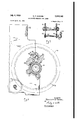
- FIG. 1 is a rear elevation of a weaving loom embodying the present invention showing a warp beam roll partially in longitudinal section;
- Fig. 2 is a view corresponding to Fig. 1 showing a split type of warp beam roll for use when weaving two widths of cloth simultaneously;
- Fig. 3 is a fragmentary side elevation partially in cross-section of the apparatus of Figs. 1 and 2 representing the warp beam roll as seen from one end with its gudgeon locked in -position;
- Fig. 4 is a view corresponding to Fig. 3 with the locking cam in the released positionshowing the warp gear disengaged fromthe let-ofl mechanism and warp beam gudgeon partiallyejected with the warp beam very nearly in position to drop into a truck for carrying it.
- Fig. 5 is a fragmentary detail view of the arrangement for clamping the warp beam flanges and driving gears to the warp beam tube;
- Fig. 6 is a fragmentary view of a locking .arrangement for a removablepedestal which may be provided for supporting the center of a removable supporting shaftwhen a slit warpv beam isutilized;
- Fig. 7 is an end view of the arrangement of Fig. 6;
- Fig. 8 is a side assembly view, with portions broken away and shown in cross-section, of a weaving loom having quickly demountable warp and cloth beam rolls in accordance with the invention
- Fig. 9 is a view of the gearing for differentially connecting the split warp beam roll of the embodiment of Fig. 2 to the let-off mechanism;
- Fig. 10 is a left end view of the difierential shown in Fig. 9;
- Fig. 11 is a longitudinal sectional view of the apparatus of Fig. 10, and I Fig. 12 is a development of one set of shown in Figs. 10 and 11.
- rollers l2 and I3 are rotatably mounted at the rear ends of the side plates II, that is, at the two rear corners of the loom frame, for rotatably supporting gudgeons ll of a warp beam roll l5.
- similarly placed rollers I6 and I l are rotatably mounted at the front ends'of the side plates II, that is, at the two front corners of the loom frame for supporting gudgeons of a cloth beam roll l8.
- and 22 are provided for the warp beam and cloth beam gudgeons respectively.
- the are carried on pivoted arms actuated by locking cams.
- the warp beam roll comprises a warp beam tube 23 composed of relatively thin stock so as tobe relatively light when the warp threads have been wound off, with bushings 24 fixed in the ends thereof, and stub'shafts 25 secured in the bushing 24.
- each stub shaft 25 comprises'an enlarged diameter plu portion 26 fitting in the bushing 24, a collar portion 21 fitting against the end of the warp beamtube 23 and a projecting portion 28.
- the collar 21 is secured to the bushing 24 in a suitable manner as by means of screws or rivets and theLbushing 24 is welded, brazed or otherwise secured to the inner surface at the end of the warp beam tube 23.
- the projecting ends 23 serve to facilitate handlingfthe loaded and empty warp beam rolls when they are carried back and, forth between the warping machine and the loom.
- is secured'to the 33 extending toward'the end of the warp beam.
- tube Y 23 is sumciently elongated to serve as a collar reinforcing the thinner stock of the warp beam tube 23 and act-as a gudgeon adapted to cooperate with the bearing rollers I2 and i3.
- the collar '33 is provided witha
- each clamp comprises a double-ear fixed jaw member 36 integral with the gear 3
- are provided for confining the warp thread to the desired width.
- are adjustably secured to the warp beam tube 23 to permit adapting the warp beam roll to being loaded with warp threads for various widths of cloth to be woven.
- the discs or flanges are provided with clamping arrangements 42 similar in construction to the clamping arrangements 35 with a clamping member 43 secured to the flanges, corresponding to the member 36 of the clamping arrangement 35.
- a warp beam controlling or-let-ofl shaft 44 is provided to which are secured pinions 45 adapted to mesh with the gears 3
- the arrangement is such that when the gudgeons H are in position the pinions 45 and the gears 31 and 32 are in mesh and when the gudgeons are ejectedthe gears are out of mesh.
- which holds the gudgeons in place is arranged also for ejecting the gudgeons l4 and the warp beam rolls when upper rollers 2
- an arm 48 is provided for rotatably supporting eachupper roller 2 l.
- the arm 46 is pivoted at the rear end of the-loom frame side plate II by means of a suitable pin or stud 41.
- a fork-shaped arm or lateral projection is formed thereon comprising two brackets 48 and 49 adapted to engage on either side an eccentric or cam 5
- screws 54 secured by lock nuts 55 may be provided for, in effect, making slight adjustments in the position of the cam face or surface of the brackets 48 and 43 contacting the surface of the eccentric 5
- the axes of rotation of the fixed pivot or lower rollers i2 and I3 are'both .belowthe axis of rotation 56 of the 7 gudgeons I4. and warp beam roll 15.
- is in the engaged position it is approximately, although not necessarily, equiangularly spaced from the rollers I2 and I3.
- the warp beam roll may be mounted and removed without any appreciable lift, the
- and '32 are'provided atlower roller i3 is so positioned that it is very nearly perpendicularly below the axis of rotation 56 of the warp beam roll.
- the roller in order' to utilize the force of gravity for holding the gudgeons H in the proper position against the rollers l2 and i3, even without any pressure being exerted on the locking roller 2
- the roller l2 may be mounted from 40 to degrees in front of the roller l3.
- a second arm 51 is secured to or made integral with the arm 46 and an ejecting roller 58 is rotatably mounted at the end of the arm' 51 which corresponds to the locking roller 2
- the axis of rotation of the ejecting roller 58 is in front of a plane drawn through the axes of the rollers
- the arms 46 and 51 are angularly so positioned that the roller 58 is fully out of engagement with the eudgeons l4 when the roll 2
- the warp beam roll l5 will fall from the loom frame and may be deposited upon a hand-truck, not shown, which may be placed thereunder.
- the warp beam roll may readily be pulled manually On to a truck from the nearly dead center position shown in Fig. 4. It will be observed that the operation of the ejecting handles 82 also disengages the gears 3
- a similar arrangement may also be provided for the cloth beam roll, but, for simplicity a nonejecting type of locking cam has been shown in which the locking roller 22, as illustrated in Fig. 8, is carried by an arm 59 cooperating with an eccentric 6
- split warp beam rolls are provided which are interchangeable with the single warp beam rolls illustrated in Fig. l.
- Fig. 2 where asplit warp beam roll is to be employed, it is preferable to provide intermediate support for the warp beam roll and a removable, readily attachable and detachable center bearing pedestal II is provided for supporting an intermediate point in a supporting shaft I2 for the warp beam tube.
- the pedestal II comprises a frame work 13 with legs 14 having adjustable feet 15 thereon adapted to contact the floor.
- the front end of the frame work I3 is adapted to rest upon an eye beam I6 which forms one of the cross members with a conventional loom frame.- For securing the front end of the bearing pedestal frame work 13 to the cross member,
- suitable claw members lI are provided having laws 18- fitting around and under the top portion of the eye beam member 18.
- the bearing pedestal frame work I3 is provided also with an adjustable screw 19 adapted to be moved against a second cross member 8
- the bearing pedestal II has a cylindrical portion 82 extending less than 180degrees, preferably approximately 120 degrees, fitting the shaft 12 and forming a fixed support therefor.
- a suitable clamping member 83 is provided having a pivot 84 in the frame work I3 slightly in front of the shaft I2, 1.
- .A projection 85 is provided in the frame work 13 and the clamping lever 83 is provided with a hinged clevis 86 adapted to snap over the projection 85 and lock the shaft I2 in place.
- the clamping lever 83 includes a block portion 88 with a cylindrical recess nearly 180 degrees in extent. engaging the upper surface of the shaft 12. It will be understood that the clamping arm 83 and the clevis 88 are so adjusted that the shaft 12' is clamped tightly and is not permitted to rotate.
- the warp beam tube is divided into as many separate tubes as there are widths of cloth to be woven and separate gears are secured to each tube, the gears being interconnected by a suitablediiferential 91, as shown in Figs. 9 to 11.
- a suitablediiferential 91 as shown in Figs. 9 to 11.
- sleeve bearings 89 are secured to the inner surface of the warp beam tube. It is to be understood that the sleeve bearings 89 are composed ofsuitable low friction material, such as bronze for example, enabling the warp beam roll to be supported upon and to revolve around the stationary shaft 12.
- the shaft 12 projects from the ends of the warp beam tubes 81 and 88 and the outer ends of the warp beam tubes are also provided with bushings 9
- the actual weight of the warp beam roll at the outer ends is, however, borne by the gudgeons I4 as in the single warp beam tube arrangement of Fig. 1.
- the gudgeons I4 ride on hearing rollers I2 and I3.
- caps 94 are secured to the bushings 9
- the warp beam tubes 81 and 88 have gears 3I and 32, respectively, secured thereto by means of clamping arrangements 35. Itwill be understood that if more than two warp beam tubes 81 and 88 were provided additional gears would be provided, one for each additional warp beam tube. Likewise, where the warp beam tube is of two or more parts additional fiangeasuch as flanges 95, are provided so that there are two flanges or discs for each warp beam tube. For the sake of adjustment to accommodate variations in desired widths of cloth to be woven, such additional flanges 95 are also provided with clamping devices 96, similar to the device 42, which has previously beendescribed. I
- both warp beam tubes 81 and 88 become freely rotatable upon the operation of either ejecting handle to disengage one or the other of the gears 3
- the use of narrow bearing rollers, as shown, having a width approximately one-third the gudgeon diameter is especially advantageous in the case of a split warp beam where a differentialv is re- ,lied upon to compensate for unavoidable lack of uniformity of tension with which the warp threads are wound in the several warp beam tubes. If sleeve bearings were employed the tendency of the warp weight to bend the shaft and cause binding would result in excessive friction loading. Such overloading of the differential would interfere with its working well to permit faster rotation of whatever warp beam tube is less tightly wound.
- the differential 91 comprises a rotating shell 98 encasing differential gears.
- the shell 98 carries aworm gear 99 meshing a worm I8I, secured to a shaft of the let-off mechanism (not shown).
- the shell 98 Concentric with the shell 98 are the center shaft 44 and a hollow shaft I82.
- the shell 98 is mounted to be freely rotatable with respect to both the center shaft 44 and the hollow shaft I82.
- a pinion I83 is secured to the shaft 44 and a pinion.
- I84 is secured to the concentric hollow shaft I82.
- Rotatably mounted in the shell 98 are planetary gears I85, I88, I81 and I88.
- One set of planetary gears I and I06 has teeth at the left-hand end of the shell 98, as seen in the view of Fig. 11, so as to mesh only with the pinion I03.
- the set of planetary gears I01 and H18 has teeth only at the opposite end so as to mesh only with the teeth of the pinion I04 on the hollowshaft I02.
- 05l06 mesh with the teeth of the other set of planetary gears lil
- the inter-meshing arrangement is illustrated schematically in Fig. 12, showing a development of the respective gears.
- the gears I08 and I are shown revolved from their actual positions, illustrated in Figs. 10 and 11.
- a warp beam roll assembly for a loom having a frame, said assembly comprising in combination a removable warp beam tube, collars carried by the ends thereof having annular grooves therein, a pair of rollers mounted on the loom frame at each end of the warp beam tube fitting said annular grooves, a pair of pivoted arms each carrying a pair of rollers adapted alternatively to engage said grooves according to the angular position of the arm, a pair of cams each engaging one of said arms and cam operating means for rotating the roller-carrying arm to a position with one roller or the other in engagement with the said collar groove, one of the rollers mounted on the loom frame at each end of the warp beam being at the bottom at an angle not exceeding twenty degrees, behind a vertical line through the warp beam center, the second roller on the frame at each end of the warp beam being in front of the said vertical line approximately -60 degrees, each roller-carrying arm having one roller in front and the other in back of the said vertical line through the warp beam center, whereby manipulation of
- a warp beam roll assembly for a loom having a frame, said assembly comprising in combination a removable warp beam tube, collars carried by the ends thereof having annular grooves therein, a pair of rollers mounted on the loom frame at each end of the warp beam tube fitting said annular grooves, a pair of movable arms each carrying a pair of rollers adapted alternatively to engage said grooves according to the position of the arm, a pair of cams each engaging one of said arms and cam operating means for moving the roller-carrying arm to a position with one roller or the other in engagement with the said collar groove, one of the rollers mounted on the loom frame at each end of the warp beam being at the bottom at a relatively small angle behind a vertical line through the warp groove supporting said collar, each having a g beam center, the second roller on the frame at each end of the warp beam being a larger angle in front of the said vertical line.
- each rollercarrying arm having one roller in front and the other in back of the said vertical line through the warp beam center, whereby manipulation of the cam operating means to engage the rear rollers with the said collar secures the warp beam roll in rotatable operating position and manipulation of said means to engage the front rollers with said collar, releases the warp beam roll and upon further movement of said means ejects it from supported position on the lower rollers.
- a warp beam roll assembly for a loom having a frame comprising a combination a removable warp beam tube, collars carried by the ends thereof having annular grooves therein, a pair of rollers mounted on the loom frame at each end of the warp beam tube fitting said annular grooves, a pair of movable arms each carrying a pair of rollers adapted alternatively to engage said grooves according to the position of the arm, a pair of cams each engaging one of said arms and cam operating means for moving the roller-carrying arm to a position with one roller or the other in engagement with the said collar groove, one of the rollers mounted on the loom frame at each end of the'warp beam being at the bottom behind a vertical line through the warp beam center, the second roller on the frame at each end of the warp beam being mounted in front of the said vertical line, each roller-carrying arm having one roller in front and the other-in back of the said vertical line through the warp beam center, whereby manipulation of the cam operating means to engage the rear rollers
- a warp beam roll for a loom comprising in combination a warp beam tube having driving gears clamped to the ends thereof, each having a hub with an annular groove therein adapted to cooperate with bearing rollers, bushings fitted in each end of said tube having stub shafts fitted therein, and warp flanges adiustably secured on said tubes for accommodating the roll to the weaving of various widths of cloth.
- a warp beam roll for a loom comprising in combination a warp beam tube having driving gears secured to the ends thereof, each having a hub with an annular groove therein adapted to cooperate with bearing rollers, and bushings fitted in each end of said tube having stub shafts fitted therein.
- a warp beam roll for a loom comprising in combination a warp beam tube, and collars secured thereto with annular grooves therein adapted to cooperate with bearing rollers for supporting the weight of the warp beam with relatively little friction when loaded, and rollers fitting into said grooves, bearing against said collars at the bases of said grooves to support the warp beam roll.
- a warp beam roll for a loom comprising in combination a warp beam tube, hollow for minimum weight and maximum strength, a reinforcing collar secured thereto having a groove therein with a hard outer surface at the base of the groove and a plurality of rollers fitting in said substantially smaller axial dimension than the diameter of said collar and having a supporting axle.
- a warp beam roll assembly for a loom weaving a plurality of widths of cloth simultaneously, comprising in combination a fixed supporting shaft, a releasable supporting means for securing said shaft intermediate the ends thereof, a
- each tube having bushings fixed therein at the ends journaled on said supporting shaft, driving gears at the ends of said tubes away from said supporting means, each having a hub adapted to cooperate with releasable supporting bearing rollers, and a pair of warp flanges on each of said tubes.
- a warp beam roll assembly for a loom weaving a plurality of widths of cloth simultaneously, comprising in combination a fixed supporting shaft, a pair of warp beam tubes concentric with said supporting shaft, each tube having bushings fixed therein at the ends journaled on said supporting shaft, driving gears secured to said tubes, each having a flanged hub adapted to cooperate with releasable supporting bearing rollers, and a pair of warp flanges on each of said tubes.
- a weaving loom having a frame, a warp beam roll and a cloth beam roll each having gudgeons with annular grooves therein, bearing rollers at the ends of said frame on each side thereof for rotatably supporting said gudgeons, rollers movably mounted above each of said gudgeons, adapted to fit in said annular grooves, and locking cams connected to said movable rollers for shifting them between gudgeon engaging and disengaging positions for looking or releasing said rolls.
- a weaving loom having a frame, a warp beam roll and a cloth beam roll each having gudgeons, bearing rollers at the ends of said frame on each side, for supporting said gudgeons, rollers movably mounted above each of said gudgeons, adapted to co-operate with said supporting rollers for confining said gudgeons, and locking cams connected to said movable rollers for shifting them between gudgeon engaging and disengaging positions for locking or releasing said rolls.
- a warp beam roll assembly for a loom having a frame comprising in combination a removable warp beam tube, collars clamped to the ends thereof, a pair of rollers mounted onthe loom frame at each end of the warp beam tube adapted to support each collar, a pair of pivoted arms each carrying a roller adapted to engage said collar or to be disengaged therefrom according to the angular position of the arm, a pair of cams, each engaging one of said arms and an operating handle on each cam for moving it into a position rotating the roller carrying arm between alternative positions, in which the said movable rollers are either in engagement with said collar, or fully disengaged therefrom, one of the rollers mounted on the loom frame at each end of the warp beam being twenty degrees behind a vertical line through the warp beam center, the second roller on the frame at each end of the warp beam being in front of the vertical line approximately 40-60 degrees, each roller-carrying arm having its roller in back of the said vertical line through the warp beam center, whereby manipulation of
- a warp beam roll assembly for a loom having a frame, said assembly comprising in combination a removable warp beam tube,collars clamped to the ends thereof, a pair of rollers mounted on the loom frame at each end of the warp beam tube for supporting said collars, a pair of pivoted arms each carrying a roller adapted to engage said collar or to be disengaged therefrom according to the angular position of the arm, a pair of cams, each engaging each of said arms and an operating handle on each cam for moving it into a position rotating the roller carrying arm between alternative positions, in which the said movable rollers are either in engagement with said collar or fully disengaged therefrom, one of the rollers mounted on the loom frame at each end of the warp beam being at the bottom behind a vertical line through the warp beam center, the second roller on the frame at each end of the warp beam being in front of the vertical line, each roller-carrying arm having its roller in back of the said vertical line through the warp beam center, whereby manipulation of the handle to
- a warp beam roll assembly for a loom having a frame comprising in combination a pair of warp beam tubes, driving gears at the ends of said tubes, pinions meshing said gears, a let-off mechanism shaft, a differential mechanism interconnecting said let-off shaft with said pinions, each tube having a collar thereon at the end adjacent the gear, and rollers supporting each collar, said rollers having substantially smaller axial dimension than the diameter of P the collar, whereby excessive friction loading is avoided and the differential is effective for adjusting relative speeds of Warp beams to tightness of warp wound thereon.
- a warp beam roll for a loom comprising in combination a plurality of warp beam tubes, each tube having a driving gear secured thereto, a plurality of pinions each meshing one of said gears, a let-off mechanism shaft, a differential mechanism interconnecting said shaft with said pinions, each tube having a collar thereon at the end adjacent the gear, and rollers supporting each collar, said rollers having substantially smaller axial dimenion than the diameter of the collar,
- a warp beam roll for a loom comprising in combination a fixed supporting shaft, an interat the bottom and at an angle not exceeding mediate support for saidshaft, a pair -of warp ll beam tubes concentric with said shaft.
- each tube having bushings fixed therein at the ends journaled on said supporting shaft, driving gears on said tubes, gudgeons at the outer ends of said tubes, supporting bearing rollers cooperating with said gudgeons having widths measured in the axial direction less than one-half the gudgeon diameter to avoid binding and friction in the event of bending of the supporting shaft, a, letoif mechanism shaft, pinions meshing said gears, and a differential mechanism interconnecting said let-off mechanism shaft and said pinions.
- a warp beam roll assembly for a loom having a frame comprising in combination a removable warp beam tube, a releasable bearing at one end of said tube comprising a collar carried by said end of said tube, and a pair of rollers mounted on the loom frame at said end of the warp beam tube, and in combination therewith, a movable arm carrying a pair of rollers adapted alternatively to engage said collar according to the position of the arm, and means for moving the roller-carrying arm to a position with one roller or the other in engagement with the said collar, one of said rollers mounted on the loom frame being at the bottom behind a vertical line through the warp beam center, the second roller on the frame being mounted in front of the said vertical line, the roller-carrying arm having one roller in front and the other in back of the said vertical line through the warp beam center, whereby manipulation of the arm-moving means to engage the rear roller with the said collar secures the warp beam roll in rotatable operating position and manipulation of said means
- a releasable bearing therefor comprising in combination a collar secured to one end of the warp beam tube, a pair of rollers mounted on the loom frame at the end of the warp beam tube for supporting said collar, a movable arm carrying a roller adapted to engage said collar or to be disengaged therefrom according to the position of the arm, an operating handle for moving the roller-carrying arm between alternative positions in which said movable roller is either in engagement with said collar or fully disengaged therefrom, one of the rollers mounted on the loom frame being on the bottom slightly behind the vertical line through the warp beam center, the second roller being in front of the verticalline, the roller-carrying arm having its roller in back of the said vertical line through the Warp beam center and above a horizontal line therethrough, whereby manipulation of the handle to engage the movable roller with the said collar secures the warp beam roll in rotatable operating position and manipulation of said-handle in the opposite direction releases the warp beam roll and permits it to be removed from the supporting position on
- a warp beam roll assembly for a loom having a frame, said assembly comprising in combination a removable warp beam tube, a collar carried at one end thereof, a pair of rollers mounted on the loom frame at said end of the warp beam tube, a movable arm carrying a pair of rollers adapted alternatively to engage said collar according to the position of the arm, a gear carried by said warp beam tube at the end near said rollers, a driving pinion rotatably supported by said frame, and means for moving the rollercarrying arm between positions with one roller or the other in engagement with said collar, one
- a warp beam roll assembly for a loom having a frame comprising in combination a removable warp beam tube, a collar secured to one end thereof, a pair of rollers mounted on the loom frame at said end of the warp beam tube for'supporting said collar, a movable arm carrying a roller adapted to engage said collar or to be disengaged therefrom accord ing to the position Of the arm, an operating handle for moving the roller-carrying arm between alternative positions in which the movable roller is either in engagement with said collar or fully disengaged therefrom, a gear carried by the warp beam tube and a driving pinion rotatably mounted in said frame at the end near said rollers, one of the rollers mounted in the loom frame being at the bottom behind the vertical line through the warp beam center, the second roller on the frame being in front of the said vertical line, the roller-carrying arm having its roller in back of the said vertical line through the warp beam center, whereby manipulation of the handle to engage the movable roller with the said collar secure
- a warp beam roll assembly for a loom having a frame and a removable warp beam tube the combination of a driving pinion rotatably mounted in the frame, a gear carried by the tube adapted to mesh with said pinion, and a releasable bearing at one end of said warp beam tube for rotatably supporting said end in the loom frame, said gear and pinion being mounted near said end of the warp beam tube, said releasable bearing comprising a gudgeon on the warp beam tube, supporting roller means mounted in the loom frame adapted to engage said gudgeon, and a movable member carrying a pair of rollers one or the other of which is adapted to engage said gudgeon according to the position of the movable member, one of said rollers being in front of the vertical line through the center of the warp beam tube and the other of said rollers being behind said vertical line, whereby the movement of the said movable member into one alternative position secures said gudgeon and said warp beam tube in
- a warp beam roll assembly for a loom having a frame comprising in combination a removable warp beam tube, collars carried by the ends thereof, a pair of rollers mounted on the loom frame at each end of the warp beam tube adapted to support said collar, a pair of movable arms each carrying a pair of rollers adapted alternatively to engage said collar according to the position of the arm, a pair of cams each engaging one of said arms and cam operating means for moving the roller-carrying arm to a position with one roller or the other in engagement with the said collar, one of the rollers mounted on the loom frame at each end Of the warp beam being at the bottom behind a vertical line through the warp beam center, the second roller on the frame at each end of the warp beam being mounted in front of the said vertical line, each roller-carrying arm having one roller in front and the other in back of the said vertical line through the warp beam center, whereby manipulation of the cam operating means to engage the rear rollers with the said collar secures the warp beam roll
Landscapes
- Engineering & Computer Science (AREA)
- General Engineering & Computer Science (AREA)
- Mechanical Engineering (AREA)
- Textile Engineering (AREA)
- Looms (AREA)
Description
y 1950 N. P. DARASH 2,514,152
RELEASABLE BEARING FOR LOOMS Filed April 1a, 1948 4 Shee'ts-Sheet 1 INVENTOR. NIBHEILHS PIIHRH'SH July 4, 1950 N. P. DARASH RELEASABLE BEARING FOR LOOMS Filed A rii 16, 1948 4 Shqets-Sheet 2 INVENTQR.
NIEHULHS E DHRHEH BY fizz? W HTTnnNEys July 4, 1950 N. P. DARASH 2,514,152
RELEASABLE BEARING FOR LOOIIS Filed April 16,- 1948 4 Sheets-Sheet 3 A loa H-r'ruRNEys y 1950 N. P. DARAS H 2,514,152
RELEASABLE BEARING FOR LOOMS Filed April 16, 1948 4 Sheets-Sheet 4 INVENTOR. NIEHDLHS F DHRHSH HTTDRNEY 5 Patented July '4, 1950 RELEASABLE BEARING FOR LOOMQ Nicholas P. Darash, Cleveland, Ohio, assignor to The Warner & Swasey Company, Cleveland, Ohio, a corporation of Ohio Application April 16, 1948, Serial No. 21,395 25 Claims. 139-97) Thi invention relates to weaving looms and concerns particularly arrangements for handling the warp and cloth beam rolls thereon. 7
It is an object to enable the warp and cloth beam rolls to be mounted and transported quickly and easily. f
A further object is to provide for the mounting of one or more warp beams according to the number of widths of cloth to be woven simultaneously.
A further object is to provide an improved releasable bearing.
Still another object is to provide a cam arrangement for roller type bearings to permit removal of warp beams and other relatively heavy rotatable members laterally and with relatively little lifting action.
Still another object is to enable emptywarp beams in a weaving loom to be removed readily by a truck without power apparatus.
Still another object of the invention is to avoid eccentricity of warp beams.
A further object is to render warp beams relatively light and to make the handling thereof relatively easy in a warping machine.
Other and further objects, features and advantages of the invention will become apparent as the description proceeds.
In carrying out the invention in accordance with a preferred form thereof, the cloth beam roll and the warp beam roll are provided with gudgeons having annular grooves, so that they are adapted to be supported by rollers and a sleeve bearing or roller bearing completely surrounding the gudgeon is unnecessary. A pair of bearing rollers with stationary pivot axes is mounted at each corner of the loom frame for supporting the warp and cloth beam roll gudgeons. The stationary pivot-axis bearing rollers are mounted with their axes at a lower level than the center line or axis of the warp or cloth beam roll to be supported. In order to lock the rolls in place, movably mounted upper rollers are also provided which are adapted to be moved into engagement with the annular gudgeon grooves. The upper rollers are mounted on movable arms actuated by locking cams for quickly and easily moving the upper rollers back and forth between engaging and releasing positions.
A better understanding of the invention will be afiorded by the following detailed description considered in conjunction with the accompanying drawings, in which Fig. 1 is a rear elevation of a weaving loom embodying the present invention showing a warp beam roll partially in longitudinal section;
Fig. 2 is a view corresponding to Fig. 1 showing a split type of warp beam roll for use when weaving two widths of cloth simultaneously; I
Fig. 3 is a fragmentary side elevation partially in cross-section of the apparatus of Figs. 1 and 2 representing the warp beam roll as seen from one end with its gudgeon locked in -position;
Fig. 4 is a view corresponding to Fig. 3 with the locking cam in the released positionshowing the warp gear disengaged fromthe let-ofl mechanism and warp beam gudgeon partiallyejected with the warp beam very nearly in position to drop into a truck for carrying it. away from the Fig. 5 is a fragmentary detail view of the arrangement for clamping the warp beam flanges and driving gears to the warp beam tube;
Fig. 6 is a fragmentary view of a locking .arrangement for a removablepedestal which may be provided for supporting the center of a removable supporting shaftwhen a slit warpv beam isutilized;
Fig. 7 is an end view of the arrangement of Fig. 6;
Fig. 8 is a side assembly view, with portions broken away and shown in cross-section, of a weaving loom having quickly demountable warp and cloth beam rolls in accordance with the invention;
Fig. 9 is a view of the gearing for differentially connecting the split warp beam roll of the embodiment of Fig. 2 to the let-off mechanism; Fig. 10 is a left end view of the difierential shown in Fig. 9;
Fig. 11 is a longitudinal sectional view of the apparatus of Fig. 10, and I Fig. 12 is a development of one set of shown in Figs. 10 and 11.
Like reference characters are utilized throughout the drawing to designate like parts.
Referring to the drawings, there is a loom having a frame comprising two side platesll as shown in Figs. 3 and 4. Lower rollers l2 and I3 are rotatably mounted at the rear ends of the side plates II, that is, at the two rear corners of the loom frame, for rotatably supporting gudgeons ll of a warp beam roll l5. As shown in Fig. 8, similarly placed rollers I6 and I l are rotatably mounted at the front ends'of the side plates II, that is, at the two front corners of the loom frame for supporting gudgeons of a cloth beam roll l8. For holding the gudgeons in place on the supporting bearing rollers I2,v l3, l6 and I1, movably mounted upper rollers 2| and 22 are provided for the warp beam and cloth beam gudgeons respectively. As will be described more in gears 3 detail hereinafter, the are carried on pivoted arms actuated by locking cams.
Referring now more in'detail to the warp beam assembly, as shown in Fig. 1, for use when weaving a single width of cloth, the warp beam roll comprises a warp beam tube 23 composed of relatively thin stock so as tobe relatively light when the warp threads have been wound off, with bushings 24 fixed in the ends thereof, and stub'shafts 25 secured in the bushing 24. As shown, each stub shaft 25 comprises'an enlarged diameter plu portion 26 fitting in the bushing 24, a collar portion 21 fitting against the end of the warp beamtube 23 and a projecting portion 28. The collar 21 is secured to the bushing 24 in a suitable manner as by means of screws or rivets and theLbushing 24 is welded, brazed or otherwise secured to the inner surface at the end of the warp beam tube 23. The projecting ends 23 serve to facilitate handlingfthe loaded and empty warp beam rolls when they are carried back and, forth between the warping machine and the loom.
For controlling the rotation of the warp beam roll by means of a conventional type. of Jet-on motion, not shown, a gear 3| is secured'to the 33 extending toward'the end of the warp beam.
Preferably, the collar '33 is provided witha,
' hardened annular groove 34 into which the rollers 12 and I3 are adapted to fit. For preventing angular or longitudinal displacement of the gudgeon collar 33 and the gear 3| on the warp' beam tube 23, clamps 35 are provided. As shown in greater detail in Fig. 5, each clamp comprises a double-ear fixed jaw member 36 integral with the gear 3| and the udgeon collar 33, a movable jaw member 31, clamping bolts 33, and elongated nuts 39 adapted to be threaded upon the bolts 33.
For confining the warp thread to the desired width, warp beam roll discs or flanges 4| are provided. Preferably the flanges 4| are adjustably secured to the warp beam tube 23 to permit adapting the warp beam roll to being loaded with warp threads for various widths of cloth to be woven. In the arrangement illus-- trated, the discs or flanges are provided with clamping arrangements 42 similar in construction to the clamping arrangements 35 with a clamping member 43 secured to the flanges, corresponding to the member 36 of the clamping arrangement 35.
As illustrated in Figs. 3 and 4, a warp beam controlling or-let-ofl shaft 44 is provided to which are secured pinions 45 adapted to mesh with the gears 3| and 32. The arrangement is such that when the gudgeons H are in position the pinions 45 and the gears 31 and 32 are in mesh and when the gudgeons are ejectedthe gears are out of mesh. Preferably in the case of warp beam rolls, the mechanism for controlling the upper rollers 2| which holds the gudgeons in place, is arranged also for ejecting the gudgeons l4 and the warp beam rolls when upper rollers 2| and 22.
the empty rolls are to be removed. As shown in the drawings, an arm 48 is provided for rotatably supporting eachupper roller 2 l. The arm 46 is pivoted at the rear end of the-loom frame side plate II by means of a suitable pin or stud 41. For actuating the arm 46, a fork-shaped arm or lateral projection is formed thereon comprising two brackets 48 and 49 adapted to engage on either side an eccentric or cam 5| having an operating handle 52 and pivoted upon a second pin or stud 53 secured to the loom side plate II. If desired for providing more precise radial adjustment of the roller 2|, screws 54 secured by lock nuts 55 may be provided for, in effect, making slight adjustments in the position of the cam face or surface of the brackets 48 and 43 contacting the surface of the eccentric 5|. 1 v
It is to be observed that the axes of rotation of the fixed pivot or lower rollers i2 and I3 are'both .belowthe axis of rotation 56 of the 7 gudgeons I4. and warp beam roll 15. When the upper roller 2| is in the engaged position it is approximately, although not necessarily, equiangularly spaced from the rollers I2 and I3. In order that the warp beam roll may be mounted and removed without any appreciable lift, the
. warp beam tube 23 at one'end thereof and, pref-i; erably, separate gears 3| and '32 are'provided atlower roller i3 is so positioned that it is very nearly perpendicularly below the axis of rotation 56 of the warp beam roll. However. in order' to utilize the force of gravity for holding the gudgeons H in the proper position against the rollers l2 and i3, even without any pressure being exerted on the locking roller 2|, the roller is so located that it is slightly to the rear of a vertical plane through the roll center line 56, e. g., between 5 and 20 degrees to the rear of such a vertical plane. The roller l2 may be mounted from 40 to degrees in front of the roller l3.
In order that the action of the arm 52 for releasing the roller 2| when the warp beam roll is to be disengaged will serve also to eject the roll, a second arm 51 is secured to or made integral with the arm 46 and an ejecting roller 58 is rotatably mounted at the end of the arm' 51 which corresponds to the locking roller 2|. The axis of rotation of the ejecting roller 58 is in front of a plane drawn through the axes of the rollers |3 and the gudgeons H. The arms 46 and 51 are angularly so positioned that the roller 58 is fully out of engagement with the eudgeons l4 when the roll 2| is in engagement therewith and vice versa.
Referring to Fig. 4, it will be observed that when the arm 52 is rotated from the position shown in Fig. 3 to that shown in Fig. 4, the arms 46 and 51 are under the action of the eccentric rotated to the positions in which the locking roller 2| is entirely out of engagement with the gudgeons i4 and the ejecting roller 58 is pressing against the cylindrical surface in the groove 34 and has forced the gudgeon 4 to rise on the roller l3, very nearly to the position of dead center, so that upon a slight further rotation of the arm 52 the roller 58 will force the warp beam axis and center of the gravity 56 to the right, i. e., to the rear of the vertical plane through the center of the roller supporting bearing roller l3 whereupon the warp beam roll l5 will fall from the loom frame and may be deposited upon a hand-truck, not shown, which may be placed thereunder. Alternatively the warp beam roll may readily be pulled manually On to a truck from the nearly dead center position shown in Fig. 4. It will be observed that the operation of the ejecting handles 82 also disengages the gears 3| and 32 from the pinions 45.
A similar arrangement may also be provided for the cloth beam roll, but, for simplicity a nonejecting type of locking cam has been shown in which the locking roller 22, as illustrated in Fig. 8, is carried by an arm 59 cooperating with an eccentric 6| actuated by a handle 82.
As illustrated in Fig. 8, it will be observed that the warp threads 83 drawn from the warp beam roll I pass around a conventional roller 84 through the loom mechanism, not shown, and emerge as cloth 85 passing around convention rollers 88 to the cloth beam roll I9.
In cases where it is desired to weave two or more narrower widths of cloth simultaneously, it is advantageous to employ a split warp beam roll, 1. e., a roll having separate'flanges for the warp threads intended to form each width of cloth. In accordance with the present invention, split warp beam rolls are provided which are interchangeable with the single warp beam rolls illustrated in Fig. l. As shown in Fig. 2, where asplit warp beam roll is to be employed, it is preferable to provide intermediate support for the warp beam roll and a removable, readily attachable and detachable center bearing pedestal II is provided for supporting an intermediate point in a supporting shaft I2 for the warp beam tube.
As shown in Fig. 8, the pedestal II comprises a frame work 13 with legs 14 having adjustable feet 15 thereon adapted to contact the floor. The front end of the frame work I3 is adapted to rest upon an eye beam I6 which forms one of the cross members with a conventional loom frame.- For securing the front end of the bearing pedestal frame work 13 to the cross member,
suitable claw members lI are provided having laws 18- fitting around and under the top portion of the eye beam member 18. For the sake of further assuring'rigidity of the mounting and preventing chattering, the bearing pedestal frame work I3 is provided also with an adjustable screw 19 adapted to be moved against a second cross member 8|- forming a part of the conventional loom'framefi n V The bearing pedestal II has a cylindrical portion 82 extending less than 180degrees, preferably approximately 120 degrees, fitting the shaft 12 and forming a fixed support therefor. For clamping the shaft 12 onthe cylin'drical rest 82 a suitable clamping member 83 is provided having a pivot 84 in the frame work I3 slightly in front of the shaft I2, 1. e., to the left thereof in the vview represented by Fig. 8. .A projection 85 is provided in the frame work 13 and the clamping lever 83 is provided with a hinged clevis 86 adapted to snap over the projection 85 and lock the shaft I2 in place. As shown, the clamping lever 83 includes a block portion 88 with a cylindrical recess nearly 180 degrees in extent. engaging the upper surface of the shaft 12. It will be understood that the clamping arm 83 and the clevis 88 are so adjusted that the shaft 12' is clamped tightly and is not permitted to rotate.
When separate widths of cloths are to be woven simultaneously preferably the warp beam tube is divided into as many separate tubes as there are widths of cloth to be woven and separate gears are secured to each tube, the gears being interconnected by a suitablediiferential 91, as shown in Figs. 9 to 11. For example. as illustrated in Fig. 2, in a case where two widths .of
cloth are to be woven a single warp beam tube 23 of Fig. l is replaced by two separate warp beam tubes 81 and 88. At the ends of the warp beam tubes 81 and 88, adjacent the supporting pedestal II for the stationary shaft 12, sleeve bearings 89 are secured to the inner surface of the warp beam tube. It is to be understood that the sleeve bearings 89 are composed ofsuitable low friction material, such as bronze for example, enabling the warp beam roll to be supported upon and to revolve around the stationary shaft 12. The shaft 12 projects from the ends of the warp beam tubes 81 and 88 and the outer ends of the warp beam tubes are also provided with bushings 9| lined with low friction sleeve bearing material 92, for the purpose of keeping the outer ends 93 of the stationary shaft I2 inalignment. The actual weight of the warp beam roll at the outer ends is, however, borne by the gudgeons I4 as in the single warp beam tube arrangement of Fig. 1. As in the arrangement of Fig. 1, the gudgeons I4 ride on hearing rollers I2 and I3. Preferably, caps 94 are secured to the bushings 9| which are, in turn, secured to inner surfaces of the outer ends of the warp beam tubes 81 and 88.
It will be understood that the warp beam tubes 81 and 88 have gears 3I and 32, respectively, secured thereto by means of clamping arrangements 35. Itwill be understood thatif more than two warp beam tubes 81 and 88 were provided additional gears would be provided, one for each additional warp beam tube. Likewise, where the warp beam tube is of two or more parts additional fiangeasuch as flanges 95, are provided so that there are two flanges or discs for each warp beam tube. For the sake of adjustment to accommodate variations in desired widths of cloth to be woven, such additional flanges 95 are also provided with clamping devices 96, similar to the device 42, which has previously beendescribed. I
Owing to the presence of the differential 91 both warp beam tubes 81 and 88 become freely rotatable upon the operation of either ejecting handle to disengage one or the other of the gears 3| and'32from either of the pinions 45. The use of narrow bearing rollers, as shown, having a width approximately one-third the gudgeon diameter is especially advantageous in the case of a split warp beam where a differentialv is re- ,lied upon to compensate for unavoidable lack of uniformity of tension with which the warp threads are wound in the several warp beam tubes. If sleeve bearings were employed the tendency of the warp weight to bend the shaft and cause binding would result in excessive friction loading. Such overloading of the differential would interfere with its working well to permit faster rotation of whatever warp beam tube is less tightly wound.
Referring to Figs. 9 to 12, it will be seen that the differential 91 comprises a rotating shell 98 encasing differential gears. The shell 98 carries aworm gear 99 meshing a worm I8I, secured to a shaft of the let-off mechanism (not shown).
Concentric with the shell 98 are the center shaft 44 and a hollow shaft I82. The shell 98 is mounted to be freely rotatable with respect to both the center shaft 44 and the hollow shaft I82. A pinion I83 is secured to the shaft 44 and a pinion. I84 is secured to the concentric hollow shaft I82. Rotatably mounted in the shell 98 are planetary gears I85, I88, I81 and I88. One set of planetary gears I and I06 has teeth at the left-hand end of the shell 98, as seen in the view of Fig. 11, so as to mesh only with the pinion I03. On the other hand, the set of planetary gears I01 and H18 has teeth only at the opposite end so as to mesh only with the teeth of the pinion I04 on the hollowshaft I02. The teeth of one set of planetary gears |05l06, in turn, mesh with the teeth of the other set of planetary gears lil|l08. The inter-meshing arrangement is illustrated schematically in Fig. 12, showing a development of the respective gears. For the sake of clarity, the gears I08 and I are shown revolved from their actual positions, illustrated in Figs. 10 and 11.
Certain embodiments of the invention and certain methods of operation embraced therein have been shown and particularly described for the purpose of explaining the principle of operation of the invention and showing its application, but it will be obvious to those skilled in the art that many modifications and variations are possible, audit is intended therefore, to cover all such modifications and variations as fall within the scope of the invention which is defined in the appended claims.
What is claimed is:
1. A warp beam roll assembly for a loom having a frame, said assembly comprising in combination a removable warp beam tube, collars carried by the ends thereof having annular grooves therein, a pair of rollers mounted on the loom frame at each end of the warp beam tube fitting said annular grooves, a pair of pivoted arms each carrying a pair of rollers adapted alternatively to engage said grooves according to the angular position of the arm, a pair of cams each engaging one of said arms and cam operating means for rotating the roller-carrying arm to a position with one roller or the other in engagement with the said collar groove, one of the rollers mounted on the loom frame at each end of the warp beam being at the bottom at an angle not exceeding twenty degrees, behind a vertical line through the warp beam center, the second roller on the frame at each end of the warp beam being in front of the said vertical line approximately -60 degrees, each roller-carrying arm having one roller in front and the other in back of the said vertical line through the warp beam center, whereby manipulation of the cam operating means to engage the rear rollers with the said collar secures the warp beam roll in rotatable operating position and manipulation of said means to engage the front rollers with said collar, releases the warp beam roll and upon further movement of said means ejects it from supported position on the lower rollers.
2. A warp beam roll assembly for a loom having a frame, said assembly comprising in combination a removable warp beam tube, collars carried by the ends thereof having annular grooves therein, a pair of rollers mounted on the loom frame at each end of the warp beam tube fitting said annular grooves, a pair of movable arms each carrying a pair of rollers adapted alternatively to engage said grooves according to the position of the arm, a pair of cams each engaging one of said arms and cam operating means for moving the roller-carrying arm to a position with one roller or the other in engagement with the said collar groove, one of the rollers mounted on the loom frame at each end of the warp beam being at the bottom at a relatively small angle behind a vertical line through the warp groove supporting said collar, each having a g beam center, the second roller on the frame at each end of the warp beam being a larger angle in front of the said vertical line. each rollercarrying arm having one roller in front and the other in back of the said vertical line through the warp beam center, whereby manipulation of the cam operating means to engage the rear rollers with the said collar secures the warp beam roll in rotatable operating position and manipulation of said means to engage the front rollers with said collar, releases the warp beam roll and upon further movement of said means ejects it from supported position on the lower rollers.
3. A warp beam roll assembly for a loom having a frame, said assembly comprising a combination a removable warp beam tube, collars carried by the ends thereof having annular grooves therein, a pair of rollers mounted on the loom frame at each end of the warp beam tube fitting said annular grooves, a pair of movable arms each carrying a pair of rollers adapted alternatively to engage said grooves according to the position of the arm, a pair of cams each engaging one of said arms and cam operating means for moving the roller-carrying arm to a position with one roller or the other in engagement with the said collar groove, one of the rollers mounted on the loom frame at each end of the'warp beam being at the bottom behind a vertical line through the warp beam center, the second roller on the frame at each end of the warp beam being mounted in front of the said vertical line, each roller-carrying arm having one roller in front and the other-in back of the said vertical line through the warp beam center, whereby manipulation of the cam operating means to engage the rear rollers with the said collar secures the warp beam roll in rotatable operating position and manipulation of said means to engage the front rollers with said collar, releases the warp beam roll and upon further movement of said means ejects it from supported position on the lower rollers. v
4. A warp beam roll for a loom comprising in combination a warp beam tube having driving gears clamped to the ends thereof, each having a hub with an annular groove therein adapted to cooperate with bearing rollers, bushings fitted in each end of said tube having stub shafts fitted therein, and warp flanges adiustably secured on said tubes for accommodating the roll to the weaving of various widths of cloth.
5. A warp beam roll for a loom comprising in combination a warp beam tube having driving gears secured to the ends thereof, each having a hub with an annular groove therein adapted to cooperate with bearing rollers, and bushings fitted in each end of said tube having stub shafts fitted therein.
6. A warp beam roll for a loom comprising in combination a warp beam tube, and collars secured thereto with annular grooves therein adapted to cooperate with bearing rollers for supporting the weight of the warp beam with relatively little friction when loaded, and rollers fitting into said grooves, bearing against said collars at the bases of said grooves to support the warp beam roll.
7. A warp beam roll for a loom comprising in combination a warp beam tube, hollow for minimum weight and maximum strength, a reinforcing collar secured thereto having a groove therein with a hard outer surface at the base of the groove and a plurality of rollers fitting in said substantially smaller axial dimension than the diameter of said collar and having a supporting axle.
8. A warp beam roll assembly for a loom weaving a plurality of widths of cloth simultaneously, comprising in combination a fixed supporting shaft, a releasable supporting means for securing said shaft intermediate the ends thereof, a
pair of warp beam tubes concentric with said supporting shaft, each tube having bushings fixed therein at the ends journaled on said supporting shaft, driving gears at the ends of said tubes away from said supporting means, each having a hub adapted to cooperate with releasable supporting bearing rollers, and a pair of warp flanges on each of said tubes.
9. A warp beam roll assembly for a loom weaving a plurality of widths of cloth simultaneously, comprising in combination a fixed supporting shaft, a pair of warp beam tubes concentric with said supporting shaft, each tube having bushings fixed therein at the ends journaled on said supporting shaft, driving gears secured to said tubes, each having a flanged hub adapted to cooperate with releasable supporting bearing rollers, and a pair of warp flanges on each of said tubes.
10. A warp beam roll assembly for a loom weaving a plurality of widths of cloth simultaneously,
comprising in combination a fixed supporting shaft, a support for said shaft intermediate the ends thereof, a pair of warp beam tubes concentric with said supporting shaft, each tube having bushings fixed therein at the ends journaled on said supporting shaft, and a pair of gudgeons, each secured to one of said tubes and adapted to cooperate with supporting bearing rollers.
11. In a weaving loom having a frame, a warp beam roll and a cloth beam roll each having gudgeons with annular grooves therein, bearing rollers at the ends of said frame on each side thereof for rotatably supporting said gudgeons, rollers movably mounted above each of said gudgeons, adapted to fit in said annular grooves, and locking cams connected to said movable rollers for shifting them between gudgeon engaging and disengaging positions for looking or releasing said rolls.
12. In a weaving loom having a frame, a warp beam roll and a cloth beam roll each having gudgeons, bearing rollers at the ends of said frame on each side, for suporting said gudgeons, rollers movably mounted above each of said gudgeons, adapted to co-operate with said supporting rollers for confining said gudgeons, and locking cams connected to said movable rollers for shifting them between gudgeon engaging and disengaging positions for locking or releasing said rolls.
13. A warp beam roll assembly for a loom having a frame, said assembly comprising in combination a removable warp beam tube, collars clamped to the ends thereof, a pair of rollers mounted onthe loom frame at each end of the warp beam tube adapted to support each collar, a pair of pivoted arms each carrying a roller adapted to engage said collar or to be disengaged therefrom according to the angular position of the arm, a pair of cams, each engaging one of said arms and an operating handle on each cam for moving it into a position rotating the roller carrying arm between alternative positions, in which the said movable rollers are either in engagement with said collar, or fully disengaged therefrom, one of the rollers mounted on the loom frame at each end of the warp beam being twenty degrees behind a vertical line through the warp beam center, the second roller on the frame at each end of the warp beam being in front of the vertical line approximately 40-60 degrees, each roller-carrying arm having its roller in back of the said vertical line through the warp beam center, whereby manipulation of the handle to engage the movable roller with the said collar secures the warp beam roll in rotatable operating position and manipulation of said handle in the opposite direction releases the warp beam roll and permits it to be removed from supported position on the lower rollers with relatively little lifting action.
14. A warp beam roll assembly for a loom having a frame, said assembly comprising in combination a removable warp beam tube,collars clamped to the ends thereof, a pair of rollers mounted on the loom frame at each end of the warp beam tube for supporting said collars, a pair of pivoted arms each carrying a roller adapted to engage said collar or to be disengaged therefrom according to the angular position of the arm, a pair of cams, each engaging each of said arms and an operating handle on each cam for moving it into a position rotating the roller carrying arm between alternative positions, in which the said movable rollers are either in engagement with said collar or fully disengaged therefrom, one of the rollers mounted on the loom frame at each end of the warp beam being at the bottom behind a vertical line through the warp beam center, the second roller on the frame at each end of the warp beam being in front of the vertical line, each roller-carrying arm having its roller in back of the said vertical line through the warp beam center, whereby manipulation of the handle to engage the movable roller with the said collar secures the warp beam roll in rotatable operating position and manipulation of said handle in the opposite direction releases the warp beam roll and permits it to be removed from supported position on the lower rollers with relatively little lifting action.
15. A warp beam roll assembly for a loom having a frame, said assembly comprising in combination a pair of warp beam tubes, driving gears at the ends of said tubes, pinions meshing said gears, a let-off mechanism shaft, a differential mechanism interconnecting said let-off shaft with said pinions, each tube having a collar thereon at the end adjacent the gear, and rollers supporting each collar, said rollers having substantially smaller axial dimension than the diameter of P the collar, whereby excessive friction loading is avoided and the differential is effective for adjusting relative speeds of Warp beams to tightness of warp wound thereon.
16. A warp beam roll for a loom comprising in combination a plurality of warp beam tubes, each tube having a driving gear secured thereto, a plurality of pinions each meshing one of said gears, a let-off mechanism shaft, a differential mechanism interconnecting said shaft with said pinions, each tube having a collar thereon at the end adjacent the gear, and rollers supporting each collar, said rollers having substantially smaller axial dimenion than the diameter of the collar,
\ whereby excessive friction loading is avoided and the differential is effective for adjusting relative speeds of warp beams to tightness of warp wound thereon.
1'7. A warp beam roll for a loom comprising in combination a fixed supporting shaft, an interat the bottom and at an angle not exceeding mediate support for saidshaft, a pair -of warp ll beam tubes concentric with said shaft. each tube having bushings fixed therein at the ends journaled on said supporting shaft, driving gears on said tubes, gudgeons at the outer ends of said tubes, supporting bearing rollers cooperating with said gudgeons having widths measured in the axial direction less than one-half the gudgeon diameter to avoid binding and friction in the event of bending of the supporting shaft, a, letoif mechanism shaft, pinions meshing said gears, and a differential mechanism interconnecting said let-off mechanism shaft and said pinions.
18. A warp beam roll assembly for a loom having a frame, said assembly comprising in combination a removable warp beam tube, a releasable bearing at one end of said tube comprising a collar carried by said end of said tube, and a pair of rollers mounted on the loom frame at said end of the warp beam tube, and in combination therewith, a movable arm carrying a pair of rollers adapted alternatively to engage said collar according to the position of the arm, and means for moving the roller-carrying arm to a position with one roller or the other in engagement with the said collar, one of said rollers mounted on the loom frame being at the bottom behind a vertical line through the warp beam center, the second roller on the frame being mounted in front of the said vertical line, the roller-carrying arm having one roller in front and the other in back of the said vertical line through the warp beam center, whereby manipulation of the arm-moving means to engage the rear roller with the said collar secures the warp beam roll in rotatable operating position and manipulation of said means to engage the front rollers with said collar, releases the warp beam roll and upon further movement of said means ejects it from supported position on the frame-mounted rollers.
19. In a warp beam roll assembly for a loom having a frame and a removable warp beam tube,
' a releasable bearing therefor comprising in combination a collar secured to one end of the warp beam tube, a pair of rollers mounted on the loom frame at the end of the warp beam tube for supporting said collar, a movable arm carrying a roller adapted to engage said collar or to be disengaged therefrom according to the position of the arm, an operating handle for moving the roller-carrying arm between alternative positions in which said movable roller is either in engagement with said collar or fully disengaged therefrom, one of the rollers mounted on the loom frame being on the bottom slightly behind the vertical line through the warp beam center, the second roller being in front of the verticalline, the roller-carrying arm having its roller in back of the said vertical line through the Warp beam center and above a horizontal line therethrough, whereby manipulation of the handle to engage the movable roller with the said collar secures the warp beam roll in rotatable operating position and manipulation of said-handle in the opposite direction releases the warp beam roll and permits it to be removed from the supporting position on the lower rollers with relatively little lifting action.
20. A warp beam roll assembly for a loom having a frame, said assembly comprising in combination a removable warp beam tube, a collar carried at one end thereof, a pair of rollers mounted on the loom frame at said end of the warp beam tube, a movable arm carrying a pair of rollers adapted alternatively to engage said collar according to the position of the arm, a gear carried by said warp beam tube at the end near said rollers, a driving pinion rotatably supported by said frame, and means for moving the rollercarrying arm between positions with one roller or the other in engagement with said collar, one
' through the warp beam center, the back roller being above a horizontal line through the warp beam center, whereby manipulationeof the armmoving means to engage the rear roller with the said collar secures the warp beam roll in rotatable operating position with the gear in mesh with said driving pinion, and manipulation of said means to engage the front roller with said collar releases the warp beam roller and upon further movement of said means ejects it from supporting position on the lower rollers and disengages said gear from the driving pinion.
21. A warp beam roll assembly for a loom having a frame, said assembly comprising in combination a removable warp beam tube, a collar secured to one end thereof, a pair of rollers mounted on the loom frame at said end of the warp beam tube for'supporting said collar, a movable arm carrying a roller adapted to engage said collar or to be disengaged therefrom accord ing to the position Of the arm, an operating handle for moving the roller-carrying arm between alternative positions in which the movable roller is either in engagement with said collar or fully disengaged therefrom, a gear carried by the warp beam tube and a driving pinion rotatably mounted in said frame at the end near said rollers, one of the rollers mounted in the loom frame being at the bottom behind the vertical line through the warp beam center, the second roller on the frame being in front of the said vertical line, the roller-carrying arm having its roller in back of the said vertical line through the warp beam center, whereby manipulation of the handle to engage the movable roller with the said collar secures the warp beam roll in rotatable operating position with the gear in engagement with said pinion, and manipulation of the said handle in the opposite direction releases the warp beam roll and permits the gear to be disengaged from the pinion and the warp beam roll to be removed from supported position on the lower roller.
22. A warp beam roll assembly for a loom having a frame and a removable warp beam tube, the combination of a driving pinion rotatably mounted in the frame, a gear carried by the tube adapted to mesh with said pinion, and a releasable bearing at one end of said warp beam tube for rotatably supporting said end in the loom frame, said gear and pinion being mounted near said end of the warp beam tube, said releasable bearing comprising a gudgeon on the warp beam tube, supporting roller means mounted in the loom frame adapted to engage said gudgeon, and a movable member carrying a pair of rollers one or the other of which is adapted to engage said gudgeon according to the position of the movable member, one of said rollers being in front of the vertical line through the center of the warp beam tube and the other of said rollers being behind said vertical line, whereby the movement of the said movable member into one alternative position secures said gudgeon and said warp beam tube in rotatably operating position with said gear in mesh with said pinion, and movement of said movable member in the opposite direction causes engagement of the other movable roller with said gudgeon to eject it from said operating position and to produce disengagement of said gear from said driving pinion. I
23. A warp beam roll assembly for a loom having a frame, said assembly comprising in combination a removable warp beam tube, collars carried by the ends thereof, a pair of rollers mounted on the loom frame at each end of the warp beam tube adapted to support said collar, a pair of movable arms each carrying a pair of rollers adapted alternatively to engage said collar according to the position of the arm, a pair of cams each engaging one of said arms and cam operating means for moving the roller-carrying arm to a position with one roller or the other in engagement with the said collar, one of the rollers mounted on the loom frame at each end Of the warp beam being at the bottom behind a vertical line through the warp beam center, the second roller on the frame at each end of the warp beam being mounted in front of the said vertical line, each roller-carrying arm having one roller in front and the other in back of the said vertical line through the warp beam center, whereby manipulation of the cam operating means to engage the rear rollers with the said collar secures the warp beam roll in rotatable operating position and manipulation of said means, to engage the front rollers with said collar, releases the warp beam roll and upon further movement of said in combination a warp beam tube having driving gears secured to the ends thereof, each having a hub adapted to cooperate with bearing rollers,
andbushings fitted in each end of said tube having stub shafts fitted therein.
- NICHOLAS PHDARASH.
REFERENCES CITED The following references are of record in the file of this patent:
UNITED STATES PATENTS Number Name Date 118,910 Cole Sept. 12, 1871 324,770 Hutchins Aug. 18, 1885 1,282,618 Neidich Oct. 22, 1918 1,749,131 Davis Mar. 4, 1930 1,827,712 Davis Oct. 13, 1931 1,984,712 Wallsten Dec. 18, 1934 2,045,035 La Rock June 23, 1936 2,447,227 Bergstrom Aug. 17, 1948
Priority Applications (1)
| Application Number | Priority Date | Filing Date | Title |
|---|---|---|---|
| US21395A US2514152A (en) | 1948-04-16 | 1948-04-16 | Releasable bearing for looms |
Applications Claiming Priority (1)
| Application Number | Priority Date | Filing Date | Title |
|---|---|---|---|
| US21395A US2514152A (en) | 1948-04-16 | 1948-04-16 | Releasable bearing for looms |
Publications (1)
| Publication Number | Publication Date |
|---|---|
| US2514152A true US2514152A (en) | 1950-07-04 |
Family
ID=21803968
Family Applications (1)
| Application Number | Title | Priority Date | Filing Date |
|---|---|---|---|
| US21395A Expired - Lifetime US2514152A (en) | 1948-04-16 | 1948-04-16 | Releasable bearing for looms |
Country Status (1)
| Country | Link |
|---|---|
| US (1) | US2514152A (en) |
Cited By (11)
| Publication number | Priority date | Publication date | Assignee | Title |
|---|---|---|---|---|
| US2609005A (en) * | 1950-01-05 | 1952-09-02 | Draper Corp | Warp beam coupling |
| US2646230A (en) * | 1951-08-20 | 1953-07-21 | Eddystone Machinery Company | Jaw arm for winding machines |
| US2840566A (en) * | 1955-04-08 | 1958-06-24 | Rohm & Haas | Preparation of nu-vinyl ethylene urea compounds |
| US2946362A (en) * | 1959-05-11 | 1960-07-26 | Talge | Food slicer blade engagement |
| US3884274A (en) * | 1974-01-09 | 1975-05-20 | Rockwell International Corp | Loom warp beam device |
| US3958844A (en) * | 1975-05-23 | 1976-05-25 | American Air Filter Company, Inc. | Bearings for rapping shaft for electrostatic precipitators |
| US3994543A (en) * | 1975-02-28 | 1976-11-30 | Lamcor Incorporated | Shaft locking device |
| US4155380A (en) * | 1978-03-23 | 1979-05-22 | Adolph Saurer Limited | Warp beam bearing for a loom |
| US4647229A (en) * | 1985-09-24 | 1987-03-03 | Lamcor, Inc. | Shaft restraining device |
| WO2010031523A1 (en) * | 2008-09-19 | 2010-03-25 | Picanol N.V. | Device for holding a shaft end and weaving machine |
| EP2146100A3 (en) * | 2008-07-16 | 2010-09-08 | Picanol N.V. | Bearing closure for clamping a part in a bearing seat |
Citations (8)
| Publication number | Priority date | Publication date | Assignee | Title |
|---|---|---|---|---|
| US118910A (en) * | 1871-09-12 | Improvement in yarn-beams for looms | ||
| US324770A (en) * | 1885-08-18 | George francis hutchins | ||
| US1282618A (en) * | 1918-04-17 | 1918-10-22 | Samuel A Neidich | Machine for winding ribbons on spools. |
| US1749131A (en) * | 1927-03-26 | 1930-03-04 | Draper Corp | Let-off mechanism for looms |
| US1827712A (en) * | 1929-12-31 | 1931-10-13 | Draper Corp | Let-off mechanism for looms |
| US1984712A (en) * | 1933-06-22 | 1934-12-18 | American Steel & Wire Co | Spool stand |
| US2045035A (en) * | 1935-03-08 | 1936-06-23 | Rock Edgar A La | Paper roll plug and shaft |
| US2447227A (en) * | 1946-04-10 | 1948-08-17 | Crompton & Knowles Loom Works | Support for warp beams in looms |
-
1948
- 1948-04-16 US US21395A patent/US2514152A/en not_active Expired - Lifetime
Patent Citations (8)
| Publication number | Priority date | Publication date | Assignee | Title |
|---|---|---|---|---|
| US118910A (en) * | 1871-09-12 | Improvement in yarn-beams for looms | ||
| US324770A (en) * | 1885-08-18 | George francis hutchins | ||
| US1282618A (en) * | 1918-04-17 | 1918-10-22 | Samuel A Neidich | Machine for winding ribbons on spools. |
| US1749131A (en) * | 1927-03-26 | 1930-03-04 | Draper Corp | Let-off mechanism for looms |
| US1827712A (en) * | 1929-12-31 | 1931-10-13 | Draper Corp | Let-off mechanism for looms |
| US1984712A (en) * | 1933-06-22 | 1934-12-18 | American Steel & Wire Co | Spool stand |
| US2045035A (en) * | 1935-03-08 | 1936-06-23 | Rock Edgar A La | Paper roll plug and shaft |
| US2447227A (en) * | 1946-04-10 | 1948-08-17 | Crompton & Knowles Loom Works | Support for warp beams in looms |
Cited By (14)
| Publication number | Priority date | Publication date | Assignee | Title |
|---|---|---|---|---|
| US2609005A (en) * | 1950-01-05 | 1952-09-02 | Draper Corp | Warp beam coupling |
| US2646230A (en) * | 1951-08-20 | 1953-07-21 | Eddystone Machinery Company | Jaw arm for winding machines |
| US2840566A (en) * | 1955-04-08 | 1958-06-24 | Rohm & Haas | Preparation of nu-vinyl ethylene urea compounds |
| US2946362A (en) * | 1959-05-11 | 1960-07-26 | Talge | Food slicer blade engagement |
| US3884274A (en) * | 1974-01-09 | 1975-05-20 | Rockwell International Corp | Loom warp beam device |
| US3994543A (en) * | 1975-02-28 | 1976-11-30 | Lamcor Incorporated | Shaft locking device |
| US3958844A (en) * | 1975-05-23 | 1976-05-25 | American Air Filter Company, Inc. | Bearings for rapping shaft for electrostatic precipitators |
| US4155380A (en) * | 1978-03-23 | 1979-05-22 | Adolph Saurer Limited | Warp beam bearing for a loom |
| US4647229A (en) * | 1985-09-24 | 1987-03-03 | Lamcor, Inc. | Shaft restraining device |
| EP2146100A3 (en) * | 2008-07-16 | 2010-09-08 | Picanol N.V. | Bearing closure for clamping a part in a bearing seat |
| WO2010031523A1 (en) * | 2008-09-19 | 2010-03-25 | Picanol N.V. | Device for holding a shaft end and weaving machine |
| BE1018286A3 (en) * | 2008-09-19 | 2010-08-03 | Picanol Nv | DEVICE FOR HOLDING AN ENDING AND WEAVING MACHINE. |
| CN102216506A (en) * | 2008-09-19 | 2011-10-12 | 必佳乐公司 | Device for holding a shaft end and weaving machine |
| CN102216506B (en) * | 2008-09-19 | 2013-07-17 | 必佳乐公司 | Device for holding a shaft end and weaving machine |
Similar Documents
| Publication | Publication Date | Title |
|---|---|---|
| US2514152A (en) | Releasable bearing for looms | |
| US1874904A (en) | Web roll supporting mechanism | |
| US3743198A (en) | Apparatus for handling rolls of strip material for unrolling thereof | |
| US3792658A (en) | Rotary printing machine with stop members for cylinder adjustments | |
| CN210133726U (en) | Winding drum device of textile machinery | |
| US2006364A (en) | Inking roller for printing machines | |
| US2363112A (en) | Web roll support | |
| US3892177A (en) | Adjustable rotary screen support with telescoping drive | |
| US4346655A (en) | Device for exchanging the form cylinder in a photogravure rotary machine | |
| US3103965A (en) | Plate bending machines | |
| US1908121A (en) | Web roll supporting mechanism | |
| US2669364A (en) | Rotatable support for cylinders | |
| US2754753A (en) | Portable ink fountain | |
| WO2021189842A1 (en) | Mesh fabric single-sided printing device | |
| US2269867A (en) | Yarn beam mounting | |
| US2635823A (en) | Roll stand | |
| JPH0530183B2 (en) | ||
| US2617447A (en) | Warp beam mount | |
| US2361858A (en) | Hoist | |
| US1979205A (en) | Printing machine | |
| US1416931A (en) | Warp beam and analogous device | |
| US1818685A (en) | Automatic belt adjuster | |
| US1835495A (en) | Reeling machine | |
| US2023463A (en) | Method and apparatus for decorating surfaces | |
| DE494413C (en) | Machine for printing paper and fabric webs |