US2503513A - Wheatstone bridge follow-up system - Google Patents
Wheatstone bridge follow-up system Download PDFInfo
- Publication number
- US2503513A US2503513A US513551A US51355143A US2503513A US 2503513 A US2503513 A US 2503513A US 513551 A US513551 A US 513551A US 51355143 A US51355143 A US 51355143A US 2503513 A US2503513 A US 2503513A
- Authority
- US
- United States
- Prior art keywords
- armature
- coils
- midposition
- potentiometer
- switch
- Prior art date
- Legal status (The legal status is an assumption and is not a legal conclusion. Google has not performed a legal analysis and makes no representation as to the accuracy of the status listed.)
- Expired - Lifetime
Links
- 238000004804 winding Methods 0.000 description 19
- 230000002441 reversible effect Effects 0.000 description 17
- 238000006073 displacement reaction Methods 0.000 description 13
- 230000000694 effects Effects 0.000 description 9
- 239000004020 conductor Substances 0.000 description 8
- 230000008859 change Effects 0.000 description 7
- 230000005291 magnetic effect Effects 0.000 description 7
- 238000010276 construction Methods 0.000 description 5
- 230000005415 magnetization Effects 0.000 description 5
- 230000007246 mechanism Effects 0.000 description 5
- 230000009471 action Effects 0.000 description 4
- 230000008901 benefit Effects 0.000 description 3
- 238000001816 cooling Methods 0.000 description 3
- XEEYBQQBJWHFJM-UHFFFAOYSA-N Iron Chemical compound [Fe] XEEYBQQBJWHFJM-UHFFFAOYSA-N 0.000 description 2
- 238000006243 chemical reaction Methods 0.000 description 2
- 238000010586 diagram Methods 0.000 description 2
- 238000010438 heat treatment Methods 0.000 description 2
- 239000000463 material Substances 0.000 description 2
- 230000004048 modification Effects 0.000 description 2
- 238000012986 modification Methods 0.000 description 2
- 229910001369 Brass Inorganic materials 0.000 description 1
- 239000010951 brass Substances 0.000 description 1
- 230000008602 contraction Effects 0.000 description 1
- 230000008878 coupling Effects 0.000 description 1
- 238000010168 coupling process Methods 0.000 description 1
- 238000005859 coupling reaction Methods 0.000 description 1
- 208000017740 grade III prostatic intraepithelial neoplasia Diseases 0.000 description 1
- 230000006698 induction Effects 0.000 description 1
- 238000009413 insulation Methods 0.000 description 1
- 229910052742 iron Inorganic materials 0.000 description 1
- 230000005389 magnetism Effects 0.000 description 1
- 230000007935 neutral effect Effects 0.000 description 1
- 238000013021 overheating Methods 0.000 description 1
- 230000010287 polarization Effects 0.000 description 1
- 230000009467 reduction Effects 0.000 description 1
- 238000004353 relayed correlation spectroscopy Methods 0.000 description 1
- 239000011435 rock Substances 0.000 description 1
- 230000035945 sensitivity Effects 0.000 description 1
- 239000000725 suspension Substances 0.000 description 1
- 238000009423 ventilation Methods 0.000 description 1
Images


Classifications
-
- G—PHYSICS
- G01—MEASURING; TESTING
- G01R—MEASURING ELECTRIC VARIABLES; MEASURING MAGNETIC VARIABLES
- G01R27/00—Arrangements for measuring resistance, reactance, impedance, or electric characteristics derived therefrom
- G01R27/02—Measuring real or complex resistance, reactance, impedance, or other two-pole characteristics derived therefrom, e.g. time constant
Definitions
- My invention relates to a control device of the type using an initially balanced Wheatstone bridge made up of two potentiometers and in which the displacement of the center arm of a first potentiometer at a control position results in operation of a heater or rotation of a motor or performance of other work and in which the performance of the work re-acts to re-set the second potentiometer so as to bring the Wheatstone bridge to a balance.
- the construction preferred includes a pair of balanced potentiometers connected at their ends so that between them they form a Wheatstone bridge.
- the contact of the center arm of one potentiometer may be shifted by hand or automatically (thermostatically, as one example), producing a current flow due to the unbalancing, greater with more extensive unbalancing.
- the current produced by the unbalance of the first (hand controlled or automatically controlled) potentiometer acting through one or other of two snap switches energizes a relay circuit by which a motor is operated in one direction or in the reverse, or a heater is increased or reduced in temperature or other work is performed or varied, according to the direction of unbalance and the motor (following it as the preferred example) performs specific work and meantime shifts the center contact of the second potentiometer so as again to balance the two potentiometers, i. e., balance the Wheatstone bridge.
- a sensitive balanced armature relay is connected in the Wheatstone bridge circuit, designed to operate snap switches which in turn start a motor either in a forward or a reverse position or apply and relieve other load.
- the sensitive balanced armature relay consists of two cores, each having two windings on each core. Two windings, one on each core, are energized when the armature is in a balanced position. These coils are in series across a line of standard voltage, 24 volts in airplane practice. They act as polarizing coils.
- the other two coils, coupled in parallel, are together in series with the center arms of the two potentiometers. As the resistance of one potentiometer is varied, it causes a voltage differential in the bridge circuit and a current flow through the parallel coils.
- the coils in parallel are oppositely energized according to the direction of unbalancing movement of the arm of the first potentiometer. correspondingly one of the core poles is strengthened and the other weakened with consequent throw of a balanced armature in one direction or the other.
- Tiltin of the armature operates a light pressure switch.
- the switch besides energizing a load relay, also disconnects the continuous coils.
- the relay When the relay is energized, it causes a motor to operate either forward or reverse, depending upon the direction of unbalance.
- the motor performs the work which is the ultimate load, and, at the same time, moves the center arm of the second potentiometer and brings it to an electrically balanced position with respect to the first potentiometer, at which point no current flows.
- One purpose of the invention is at the time of adjusting a first potentiometer of a pair of balanced potentiometers forming a Wheatstone bridge, to secure positive switch energization of a circuit in which or by which work is to be accomplished, and to maintain the current in this circuit up to the time when the Wheatstone bridge shall again have been balanced by automatic corrective variation of the unbalance by adjustment in the second potentiometer,
- a further purpose is to use the current due to initial unbalance of a Wheatstone bridge to effect snap switch control of work circuits which are alternatively energized and which ultimately correct the unbalance.
- a further purpose is to use a difference, such 3 as that in temperature within an area. to be kept at uniform temperature, as a means of operating corrective temperature changing mechanism, the correction restoring the desired relation and then ceasing to operate.
- a further purpose is to produce a control relay having a balanced relay armature and cores which are magnetized to create poles in said armature by series core windings, to strengthen one and weaken the other of said poles selectively by core windings in parallel supplied by current due to unbalance of one potentiometer of a pair of potentiometers normally balanced in a Wheatstone bridge, to operate a spring retracted snap switch in either of two work circuits selectively by reason of tilt of the armature in one direction or the other, preferably shutting off current to the series at the same time, and to reset the Wheatstone bridge by altering the second potentiometer to compensate for the change in the first, reducing the current in the parallel coils meantime to a point where the snap switch automatically opens.
- a further purpose is to use a pair of potentiometers in an initially balanced Wheatstone bridge to throw an armature by which snap switches are actuated selectively in work circuits, to maintain the snap switches in closed position by currents due to the unbalance of the potentiometers, to again and automatically balance the Wheatstone bridge by setting a second potentiometer to compensate the first, thus progressively reducing the current due to unbalance, and opening the work circuit current as soon as the magnetic effect of the current due to unbalance is insufiicient to hold the snap switch against opening movement.
- a further purpose is to control operation of switches for work circuits, permissible forward and reverse motor circuits, or heaters to be turned on and cut off or reduced in heating effect, by a sensitive coil-operated balanced armature, in whose coils both series and parallel coil connections are used, the series coils to give polarity to the armature in its neutral position and the parallel coils, energized for example, as a result of unbalance of a Wheatstone bridgeselectively to increase the magnetization of one or other of the positive or negative magnet poles controlling the armature, and to reduce the strength of the other pole, whereby a much greater contrast of magnetization of the armature is secured and the armature becomes effective for snap switch actuation.
- a further purpose is to use the unbalance of a Wheatstone bridge as a basis for throwing a snap switch against reversing pressure, utilizing the snap switch in a load circuit and resetting the bridge by means of the current flowing in the load circuit.
- a further purpose is to use the unbalancing of one potentiometer of a pair of potentiometers making up a Wheatstone bridge as a means ofdiverting current supplied from an outside source into a sensitive control relay, magnifying the eflect upon the relay armature so that one or other of work-circuit-controlling snap switches is thrown against a resetting pressure such that when the current becomes greatly reduced the snap switch is reversed.
- a further purpose is to use a minute current from unbalance of a Wheatstone bridge to operate controlling coils in an electromagnetically polarized relay. sothat one pole is strengthened and another weakened and to close one or other of two snap switches in alternative load circuits through the relay armature, resetting the bridge by the operation of the load circuit.
- a further purpose is to supply work circuits which are opposite in their effects one with respect to the other through a snap switch control and control the snap switch by an armature whose strength of attraction and repulsion is due to series polarizing coils upon which are impressed parallel control coils.
- a further purpose is to provide pairs of electric coils upon separate magnetic cores, respectively, in series across a source of energy and in parallel, receiving current through the center arms of potentiometers, between which arms voltage differences have been created, and to operate snap switches in work circuits by combinations of currents flowing in these coils.
- a further purpose is to polarize an armature, to unbalance a Wheatstone bridge in order to magnify the effect of one pole and reduce that of the other, and use the armature to throw a snap switch against spring retardation in order to energize a load circuit or shut it off sharply.
- a further purpose is to provide a pair of electro-magnetic cores and pole pieces with two coils in series and two coils in parallel, using the series coils to balance an armature and the parallel coils to add to the strength of one pole and reduce the strength of the other pole whereby the armature can be thrown strongly in one direction or the opposite at will and contacts made by it can be used to close work circuits.
- a further purpose is to operate a load by unbalancing one of two potentiometers making up a Wheatstone bridge, to use the current set up as a means of operating a current balanced relay and to cut oil the total current except when the relay is in use.
- a further purpose is to balance a control armature by adjusting its pivot point with respect to poles by which it is affected or to vary its leverage for switch operation.
- Figures 1 and 9 are diagrammatic illustrations showing a Wheatstone bridge application passing current through delicately balanced control armatures and local motor circuits.
- Figures 2 and 3 are a front elevation and a side elevation, largely in diagram, showing a balanced armature construction through which the invention may be applied.
- Figure 4 is a perspective view of a structure embodying the diagrammatic material of Figures 1, 2 and 3 and which has been successfully used.
- Figure 5 is a top plan view of the structure seen in Figure 4.
- Figure 6 is an and elevation of the structure seen in Figure 5.
- the load circuits fed by the relayscontain each not only the load but means for resetting the center arm of the second potentiometer, with the result that the'snap switch opens and shuts oi! the circuit in which the load is included.
- the current in the parallel coils will greatly increase the magnetization of the north pole of the core and will reduce or reverse the strength of what was initially the south pole.
- the balanced armature will be tilted (thrown) in clockwise or counter-clockwise direction and by a strength of magnetic reaction much in excess of that which would be available if the current of unbalance through the .parallel coils were depended upon alone to tilt the armature.
- the tilt of the armature is used to throw one snap switch or the other against a continuing resistance, thus closing one or other of two relay work circuits is or Gil and coincidently opening the circuit through the series coils.
- the coils 6i and 62 in the relay load circuits control, respectively, switches 63 and 54, thus passing current from the mains through connections 65 or 66 to supply forward or reverse motor windings 61 or 68 of a motor 69 shown in Figures 4 and 5.
- the common return is shown at 10 and limit switches are inserted at Ii and 12 in the forward and reverse connections. In Figure 1 forward and reverse directions of drive of the same motor are intended.
- FIGs 4 and an opertive mechanism is shown embodying the structure illustrated diagrammatically in Figures 1, 2 and 3 and in which the motor 69 is the reversing motor which is operated in either direction, responsive to the movement of an arm upon a potentiometer is not there shown, through series and parallel coils upon the relay.
- the balanced armature operates snap switches 40 and 4
- the armature shaft is extended by any suitable coupling, not shown, for connection with any suitable work.
- any suitable coupling not shown, for connection with any suitable work.
- Figures 4, 5 and 6 the various .parts are shown as they have actually been used, except that the first potentiometer is separate from the base.
- the motor unit ( Figures 4, 5 and 6) is mounted pon the same base It as the frame of the polarized relay.
- the first potentiometer and lever for setting it are mounted separately at H.
- the second potentiometer is mounted upon the upper right or the motor unit in Figures 4 and 5.
- the cover 19 for the rotating shaft appears as well as brackets supporting the motor, the motor housing, relays, etc.
- gear box II for the motor housing, limit switches H, 12, extra mount 19 for the motor, by which the motor may be mounted "upside down” as compared with the illustration in Figure 4, if it prove more convenient to the user.
- Brackets for support of the parts and conduit 00 for wires also appear. Sockets II are shown for outside connection and indicator 92 appears in Figure 4.
- the sensitive relay is supported upon a threepoingbearing, having the points 93, 94, II ( Figure After the center arm of the first potentiometer has been shifted, the operation of the motor, in whichever direction driven, resets the arm I! so as to balance the potentiometer II with the potentiometer i6, balance the Wheatstone bridge and reduce and finally cut oil the current caused to fiow through the parallel windings by the initial unbalance of the bridge.
- the balanced armature is best shown in Figures 2, 3 and 5 in which a mounting bracket 86 ( Figure 5) supports return magnetic circuits for the two cores 36 and 31.
- a three-point suspension is used for the bracket and frame, comprising resilient supports 91, ll, 99, each of which includes spaced resilient (such as rubber) washers between which is gripped a part of the bracket or frame so as resiliently to support the balanced armature, the coils and the switches as a unit.
- the cores are connected with strips ll, 92 ( Figure 2) of magnetizable material which are bent parallel to each other at 93 and 94, and are fastened together back to back.
- the magnetic circuit thus provided extends to the armature and is there interrupted to provide a pivot support for the armature as seen in Figures 2 and 3.
- the strip 95 fits between two snap switches 49 and 4 I. These snap switches are of a type which snap to position by ressure or armature-carried lugs 96 and 91 pressing against operating pins 98 and 99 by which the switches are thrown.
- the lugs 96 and 91 maintain pressure against the pins in proportion to the current passing through the parallel windings.
- the throw oi the switch takes place by snap action in both directions of throw.
- the snap takes place by reason of pressure of a pin movable to an extent of pin throw movement less than snap throw.
- the switch levers automatically reverse when throwing (maintaining) pressure has been removed.
- the two cores support spools III, III having Figure 10 is a section of Figure 10 along the line In -m.
- Figure 10 is a circuit diagram showing the circuit arrangements in Figure 10.
- Figure 11 is a perspective of a contact ring in Figure 10.
- Figure 12 is a diagrammatic view showing thermostatic operation.
- thermostat switch shifted by reason of change in temperature of a compartment is relied upon to close or open a switch or to slide a switch contact along the surface of a plurality of contacts.
- the thermostat provides automatic variation of the position of a center arm along a potentiometer scale.
- a similar center arm may be moved by hand along this potentiometer scale.
- the potentiometer may be used as in Figure l as part of a Wheatstone bridge whose unbalance sets in motion a motor, let us say in clockwise direction, using a thermostatically operated contact arm to engage with the contacts of a resistance or with a single switch or a plurality of switches so as to operate a cooperative potentiometer.
- a second potentiometer may be adjusted to balance the Wheatstone bridge and to cut off the current due to unbalance.
- a Wheatstone'bridge I5 is made up of potentiometers l6 and I! having center arms [8 and I9 dividing the potentiometers into resistance segments 20, 2
- Current is supplied to the Wheatstone bridge terminals 24, 25 from positive main 25 and negative main 2'! by conductors 28 and 29.
- the middle arms are intended normally during inaction to be so located along their contact scales that no current tends to flow between them-i. e., in balanced positionbut in Figure 1 are shown as unbalanced.
- the arm l8 may be thrown about its center 30 by hand or automatically (see Figure 1).
- One example of automatic operation would be thermostatic operation, by a thermostat 3
- the amount of unbalance will bear a relation to the extent of movement of the arm and difference in potential is then created between the middle am ll of the first potentiom- 6 eter and the middle arm I! of the second potentiometer.
- This difierence in potential is applied to a balanced armature control relay 43 through conductors 34 and 35 (see Figure 1).
- the control relay as shown comprises a pair of relay cores 35 and 31 magnetically reacting upon a balanced armature 3B pivoted at 39 (see Figure 9).
- the armature and its relation to the cores are seen in Figures 2 and 3, which also show the magnetic circuit for the cores.
- are closed, one at a time, against a resilient opening pressure as the result of tilting movement of the relay. Later the closed switch is allowed to open.
- the cores 3!; and 31 are both double wound as indicated diagrammatically in Figures 1, 2 and 3.
- the coils 42, 43 of one pair are polarizing coils surrounding the respective cores, connected in series through conductor 44 and supplied with current by conductors 45, 45.
- This polarizing current passes through switch arms 41, 48 and contacts 49 and 50.
- These series coils normally give opposite polarity to the terminal poles 5i and 52 of cores 36 and 31. This polarity has been indicated arbitrarily upon the poles in Fig. 9 as north at the left hand and south at the right hand.
- the polarization of the cores creates opposite polarity south and north respectively in the ends of the balanced armature so as, in the absence of other magnetization, to hold the armature in balanced position, when it is initially balanced, as it will normally be due to the springs, for example in the snap switches.
- the switch arms 41 and 48 ( Figures 1 and 9) are capable of making contact at 53 and 54, closing one or other of two relay load circuits.
- a snap switch is used of a type which snaps open under pressure and will snap back if the pressure he not maintained. It is very desirable that the switches shall not be subject to chatter or other trouble from vibration and that in each direction of movement each switch shall definitely close and definitely open, rather than close and open gradually or uncertainly.
- the second windings, coils 55 and 56, one on each of the cores 36 and 31, are connected in parallel at 51 and 58, and are supplied with current by junction points 34 and 35 connected to arms i8 and I9 so that current from the mains will fiow through these coils in parallel whenever the relative positions of the contacts controlled by arms l8 and I9 unbalance the Wheatstone bridge.
- arm l8 has been adjusted by hand or automatically, the circuit will be unbalanced and current will flow through the :parallel coils about the cores until the potentiometers have again been balanced.
- the current will flow in different directions according to the direction in which the arm l8 v 9 insulating ends I02, I33.
- the spools carry one winding each of the series pair of coils and one winding each of the parallel pair of coils, thus having two windings upon each core.
- Plates III4, I between strip II and the magnet return circuit form a convenient support for the pivot upon which the light balanced armature is carried so that the armature will reach over the two poles.
- the pivotal pin for the balanced armature Is adjustable lengthwise of the armature, or, alternatively, lengthwise oi the pole pieces in order to make it possible very exactly to balance the armature when it is polarized by the series coils upon or about the control cores.
- this adjustment is shown as corresponding with the position of the parts in Figure 2 except that in Figure 2, plates I06, front and back, and screws I01, have been omitted. The screws fit through slots I08 into threaded holes I".
- the plates carry bearing openings IIO.
- the pivot is carried by a bracket II I fastened to the armature plate II2 by bolt II3 passing through a slot II4 extending longitudinally with respect to the armature.
- the bracket carries rods II! which serve as the pivots.
- the pivot can be adjusted longitudinally of the armature itself, so as to leave unequal lengths of armature on opposite sides of the pivot location, and in this way to balance the armature even if there be slightly unequal strength of core poles.
- a guide III in each snap switch supports a pin III which is prevented from falling through the guide, so that the pin is in line with a properly supported diaphragm II8, of any one of the types indicated.
- the pins for the two snap switches are in line, each with one or other of projections 96, 91 ( Figure 2) which are carried by the armature on opposite sides of its center. These projections are supported from the armature body by rods H9, I20 ( Figure 2) which are threaded into the arms.- ture and are locked in adJusted position by nuts I2I. By these rods the height of the limit of movement of the snap-switch-operating pins can be adjusted.
- Figure 9 is a diagrammatic construction corresponding generally to Figure l but having several marked differences from that of Figure 1.
- a second diiierenoe of Figure 9 with respect to Figure 1 is as to the two potentiometers.
- they are separated widely to indicate that the first potentiometercan be at any suit able control point and the second potentiometer wherever the motor-let us say-is located.
- the potentiometer-s have been brought together into something more nearly approaching the normal Wheatstone bridge though it is the intention still that the second potentiometer neednotbeclosetotheflrstbutcanbespaced from the first to meet the requirement 01' motor location, etc.
- the third difierence is that an indicator (signal) light I22 is shown in Figure 9 connected to show when either of the relays is in operation. whereas in Figure 1, while such an indicator (signal) light can be used in the same location, it has not been shown.
- Figure 9 form is suited to mechanical operation instead of the hand throwing o! the first potentiometer middle arm for which the Figure 1 form is primarily intended.
- a double switch is shown as connected with the throwing mechanism, so that the act of throwing the switch will electrically energize the series and also the parallel windings or coils which will be dead except when the middle arm of this potentiometer is actually being moved.
- Figure 10 One form of such a switch is shown in Figure 10 with a detail in Figure 11.
- double switch contacts I23, I24 energize conductor I25 when pressure is placed upon I23 or I24 to cause movement 0! the middle arm.
- the middle arm is insulated from conductor I25 but is mechanically connected with it so that this middle arm can be moved by moving either of the operating mechanisms I23 or I24.
- the conductor I2! is thus energized in either event, causing energization of both series and shunt coils, until opening 01 one or the relay switches at 49 or II interrupts current through the series coils. Resetting of the middle arm of the potentiometer reduces holding pressure upon a snap switch which has been thrown until the switch snaps open.
- the operating button or mechanical lever for the middle arm of the first potentiometer is not shown in Figure 10 but the shaft connected with it is shaft I23. It is used when the unbalance or the first potentiometer is effected through this shaft I26, electrically conducting pin I21 and an insulating collar I28.
- the insulation collar carries an electrically conducting annulus I28 shown in Figure 11 whose ends are transversely turned at I30 and I3I so as to present contacts to be closed against the pin. These contacts are given an allowance for play with respect to the electrically conducting pin.
- the grounded amphenol contact I33 is connected with one side I34 of the first potentiometer for the Wheatstone bridge.
- a second amphenoP' contact I35 is connected with the .contact I36 of the potentiometer and a third 11 amphenbl contact I31 is connected with the center pin I21 by a contact I38.
- the fourth amphe'nor contact is connected to the tang I39 01 the annulus I29.
- the spacing of the center pin from the contacts I30 and I3I is effected by a spring I40 which is wrapped about a supporting pin HI and extended so that it will bear against the two sides of pin I21 and will also bear against or lie close to a non-conducting stop pin I42 so that the spring will prevent pin I21 from moving either way far enough to make contact with either contact I30 or I3I except as the spring bends.
- Threads are shown at I43 by which the potentiometer is mounted to the housing I44.
- a signal light I22 is shown supplied with current by conductors I46 and I46. This light is operative when the switch I21, I30, I3I of Figure 10 is turned in either direction and remains operative until the complete control has been effected, i. e. until the snap switch actuated by the polarized relay has returned to open position due to the holding action of relay contacts 83 and 64.
- the cut-out switch at the potentiometer arm in the hand thrown form makes it possible to cut the current from the whole system during times when the device is not in operation.
- the series coils are opened when one relay circuit or the other is closed in order that the parallel coils will have complete control of the polarized relay, improving the accuracy of resetting. This frees the armature from series coil control for return to balanced position when the pressure of the armature against one or other of the switch pins is less than the retracting pressure of the load relay circuit snap switch.
- the second potentiometer may be located physically so closely adjacent to the motor which is being operated (see Figure also) that the motor may be used to swing the second potentiometer middle arm to its compensating position.
- FIG 12 an automatic oil cooling system is shown such as is suitable for protection of oil from over-heating in an airplane oil system.
- the one function is that the armature through gearing I5I, I52 operates a screw I53 whose nut I54 throws a ventilating flap I55 to closed, "ttled or “full open posi tion, or some fraction of this distance, cooling off the oil in the system.
- the nut is swiveled to 'the flap.
- the movement of the armature compensates by physical movement of the arm I9 of this second potentiometer so that whether the first potentiometer arm has moved in clockwise or counterclockwise direction, the second potentiometer arm is moved so as to compensate for the movement of the first and to bring the flap to a position which maybe made standard until operation conditions change and to change the position of the flap as may be required to meet new conditions.
- Balancing the bridge causes either cooling or heating of the oil in the oil cooler radiator with corresponding reaction upon the spiral thermostat and corresponding retractive movement of the arm of the first potentiometer.
- the action of the second potentiometer arm will not be complete because on its corrective movement it will reach a balancing position with the first potentiometer arm before it is wholly compensated for the initial change in the first potentiometer.
- the changes in position of arm I8 because of the corrective effect upon the thermostat will reduce or perhaps in individual cases obviate the corrective movement of the second potentiometer arm.
- the actuating shaft in Figure is insulated from but is mechanically connected with the potentiometer shaft in line with it, and the potentiometer shaft in turn is insulated from the potentiometer middle arm but mechanically operates it. .As a result when the actuating shaft is turned in either direction to close one or other of the contacts 3. and ll against the pin the potentiometer shaft is energized but the middle arm of the potentiometer is not energized exceptas it is energized because of the unbalance of the potentiometer.
- FIG. 5 is shown a construction by which the sensitivity of the armature may be adjusted.
- Brass screws I56 pass through the armature plates so that the ends of the screws may be made to engage with the faces of the cores II and 31.
- the screws are preferably threaded into the plates and are held in adjusted positions by lock nuts I" above the plates.
- lock nuts I" above the plates.
- the screws can be backed on so that they have no effect in spacing the armature at its closest point fromthe faces of the poles of the cores or they can be screwed down to space the magnetizable armature from the poles of the cores to varying degrees giving a very delicate adjustment of the amount oi magnetic efl'ect in the cores which is required to throw the armature.
- threaded washers I58 may be screwed to the armatures.
- a control relay comprising a centrally pivoted armature, cores on either side of the armature, disposed transversely to the armature on opposite sides of the pivot; and each adapted to pull magnetically on the armature, a polarizing coil around each core, a source of current connected to the polarizing coils in a direction to set up opposing pulls by the coils and cores on the armature, a control coil around each core, reversing control voltage means connected to the control coils in a direction to set up pulls by the control coils and cores on the armature in the same direction, a pair of switches, on operatively connected to the armature for displacement when the armature pivots in each direction from mid position, each switch having a set of contacts open when th armature is in midposition and closedwhen the armature pivots from midposition in one direction, a pair of load relays, a pair of load relay circuits, each including one switch and one load relay, switch means operative when the armature
- a control relay comprising a centrally pivoted armature, cores on either side of the armaturedisposedtransverselywthearmatureon either side 01' the pivot and each adapted to pull magnetically on the armature, a polarizing coil on each core, a source 01' current connected to the polarizing coils in a direction to set up opposing pulls by the coils and cons on the armature, a control coil around each core, reversing control voltage means conected to the control coils in a direction to set up pulls by the control coils and cores on the armature in the same direction, a pair of double throw switches, one operatively connected to the armature for displacement when the armature pivots in each direction from midposition, each switch having a set or contacts closed when the armature is in midposition and opened when the armature pivots from midposition in one direction and another set or contacts closed when the armature pivots from midpomtion in that direction and opened when the armature returns to midposition, connections interposing the
- a control relay comprising a centrally pivoted armature, cores on either side of the armature disposed transversely to the armature on either side of the pivot and each adapted to pull magnetically on the armature, a polarizing coil around each core, a source of current connected" to the polarizing coils in a direction to set up opposing pulls on the coils and cores of the armature, a control coil around each core, reversing control voltage means connected to the control coils in a direction to set up pulls by the control coils and cores on the armature in the same direction, spring means urging the armature toward midposition, a pair of double throw switches, one operatively connected to the armature for displacement when the armature pivots in each direction from midposition, each switch having a set oi.
- a control relay comprising a centrally pivoted armature, cores on either side of the armature disposed transversely on either side of the pivot and each adapted to pull magnetically on the armature, a polarizing coil around each core, a source of current connected to .the polarizing coils in a direction to set up opposing pulls by the coils and cores on the armature, a control coil around each core, reversing control voltage means connected to the control coils in a direction to set up pulls by the control coils and cores on the armature in the same direction, a pair of double throw snap acting switches, one operatively connected to the armature for displacement when the armature pivots in each direction from midposition, each switch having a set of contacts closed whenthe armature is in midposition and open.
- a pair of load relays when the armature pivots from midposition in one direction and another set of contacts closed when the armature pivots from midposition in that direction and open when the armature is restored to midposition, a pair of load relays, a pair of load relaycircuits each including one of the load relays and one of the set", of contacts open when the armature is in midposition and closed when the armature pivots from midposition, and connections interposing the sets of contacts which close when the armature is in mid.- positlon and open when the armature pivots from midposition between the source and the polarizing coils.
- a control relay comprising a centrally pivoted armature, cores on either side of the armature disposed transversely to the armature on either side of the pivot and each adapted to act magnetically on the armature, a polarizing coil around each core, a source of current connected to the polarizing coils in series in a direction to set up opposing pulls by the coils and cores on the armature, a control coil around each core, reversing control voltage means connected to the control coils in parallel in a direction to set up pulls by the contro coils and cores on the armature in the same direction, a pair of double throw switches, one operatively connected to the armature for displacement when the armature pivots in each direction from midposition, each switch having a set of contacts closed when the armature is in midposition and open when the armature pivots from midposition in one direction, and another set of contacts closed when the armature pivots from midposition in that direction and open when the armature is restored to midposition
- a control relay comprising a centrally pivoted armature,'cores on either side of the armature disposed transversely to the armature on either side of the pivot and each adapted to pull magnetically on the armature, a polarizing coil around each core, a source of current connected to the polarizing coils in series in a direction to set up opposing pulls by the coils and cores on the armature, a control coil around each core, re versing control voltage means connected to the control coils in parallel in a direction to set up pulls by the control coils and cores on the armature in the same direction, a pair of double throw snap switches spring urged toward midposition, one operatively connected to the armature for displacement when the armature pivots in each direction from midposition, each switch having a set of contacts closed when the armature is in midposition and open when the armature pivots from midposition in one direction and another set of contacts closed when the armature pivots from midposition in that direction and open when the arma
- a control relay comprising a centrally pivoted armature, cores on either side of the armature disposed transversely to the armature on either side of the pivot and each adapted to pull magnetically on the armature, a polarizing coil around each core, a source of current connected to the polarizing coils in a direction to set up opposing pulls by the coils and cores of the armature, a control coil around each core, a Wheatstone bridge having balancing arms, a source connected to opposite points of the bridge from the arms, connections from the balancing arms to the control cois in a direction to set up pulls by the control coils and cores on the armature in the same direction, a pair of switches, one operatively connected to the armature for displacement when the armature pivots in each direction from the midposition, each switch having a set of contacts closed when the armature rocks from midpositionand open when the armature returns to midposition, a pair of control relays, a pair of relay circuit
- a control relay comprising a centrally pivoted armature, cores on either side of the armature disposed transversely to the armature on either side of the pivot and each adapted to pull magnetically on the armature, a polarizing coil around each core, a source of current connected to the polarizing coils in a direction to set up opposing pulls by the coils and cores on the armature, a control coil around each core, a Wheatstone bridge having balancing arms, a source connected to opposite points ,on the bridge from the balancing arms, connections from the balancing arms of the bridge to the control coils in a direction to set up puls by the control coils and cores on the armature in the same direction, a pair of double throw snap switches spring urged toward midposition connected to the armature for displacement when the armature pivots in each direction from midposition, each switch having a set of contacts closed when the armature is in midposition and open when the armature pivots from midposition in one direction and another
- a control relay comprising a centrally pivoted armature, cores on either side of the armature disposed transversely to the armature on either side of the pivot and each adapted to pull magnetically on the armature, a polarizing coil around each core, a source of current connected to the polarizing coils in a one operatively connected to the armature for displacement when the armature pivots in each direction from midposition, each switch having a set of contacts closed when the armature pivots from midposition in one direction and open when the armature is returned to midposition, means for disconnecting the source form the polarizing coils when the armature is pivoted from midposition, a Wheatstone bridge having balancing arms, a source connected to the bridge at points opposite to the balancing arms, connections from the balancing arms to the control coils in a direction to set up pulls by the control coils and cores on the armature in the same direction, a reversible motor having reverse windings,
- a control relay comprising a centrally pivoted armature, cores on either side of the armature disposed transversely to the armature on either side of the pivot and each adapted to pull magnetically on the armature, a polarizing coil around each core, a source of current connected to the polarizing coils in a direction to set up opposing pulls by the coils and cores on the armature, a control coil around each core, spring means urging the armature toward midposition, a pair of double throw switches, one operatively connected to the armature for displacement when the armature pivots in each direction from midposition, each switch having.
- a set of contacts closed when the armature is in midposition and open when the armature pivots from midposition in one direction and another set of cohtacts closed when the armature pivots from midposition in that direction and open when the armature is restored to midposition a Wheatstone bridge having balancing arms, a source connected to opposite points on the bridge from the balancing arms, connections from the balancing arms to the control coils in a direction to set up in the control coils and cores pulls on the armature in the same direction, a pair of relays having load contacts, a pair of relay circuits each including one of the relays and one of the sets of contacts closed when the armature pivots from midposition and open when the armature is restored to midposition, a motor having reverse windings, a pair of motor circuits-each including one of the motor windings and the load contacts of one of the relays, connections placing the sets of contacts closed when the armature is in midposition between the source and the polarizing coils, and mechanical
- a control relay comprising a centrally pivoted armature, cores on either side of the armature disposed transversely to the armature on either side of the pivot and each adapted to pull magnetically on the armature, a polarizing coil around each core, a source of current connected to the polarizing coils in a direction to set up opposing pulls by the coils and cores on the armature, a controlling coil around each core, a Wheatstone bridge having balancing arms, a
- a pair of switches each operatively connected to the armature for displacement when the armature pivots in one direction from midposition, each switch having contacts closed when the armature pivots from midposition in one direction and, opened when the armature is restored to midposition, a pair of load relays, load circuits each including one of the sets of contacts and one of the relays, an operating member for one of the balancing arms and a switch actuated by the operating member for closing the circuit to the source when the operating member is inactive.
- a control relay comprising a centrally pivoted armature, cores on either side of the armature disposed transversely to the armature on either side of the pivot and eachadapted to pull magnetically on the armature, a polarizing coil around each core, a source of current connected to the polarizing coils in a direction to set up opposing pulls by the coils and cores on the armature, a control coil around each core, a Wheatstone bridge having balancing arms, a source connected to opposite points on the bridge from the balancing arms, a pair of switches, each operatively connected to the armature for displacement when the armature pivots in one direction from midposition, each switch having contacts closed when the armature pivots from midposition in one direction and open when the armature is restored to midposition, a pair of load relays, load circuits each including one of the sets of contacts and one of the load relays, an operating member for one of the balancing arms, a switch actuated by the operating member for closing the circuit to
- a Wheatstone bridge having balancing arms, an operating member for one of the balancing arms, a source of current connected to opposite points of the bridge from the balancing arms, a switch actuated by the operating member for closing the circuit to the source when the operating member is manipulated and opening the circuit when the operating member is inactive, and automatic means including a relay and a motor operatively interconnected for restoring balance to the operating arms.
- a Wheatstone bridge having balancing arms, an operating member for one of the balancing arms, a source of current connected to opposite points of the bridge from the balancing arms, a switch actuated by the operating member for closing the circuit to the source when the operating member is manipulated and opening the circuit when the operating member is inactive
- automatic means including a relay and a motor operatively interconnected for restoring balance to the operating arms and connections from the source to the opposite points of the bridge for holding current on the bridge during a period of unbalance notwithstanding that the switch actuated by the operating member may open.
- a control relay comprising a centrally pivoted armature, cores on either side of the armature disposed transversely to the armature on either side of the pivot and each adapted to pull magnetically on the armature, a polarizing coil around each core, a source of current connected to the polarizing coils in a direction to set up opposing pulls by the polariz-' ,other set of contacts closed when the armature pivots from midposition in that direction and open when the armature is restored to midposition, a Wheatstone bridge having balancing arms, a source connected to opposite points on the bridge from the balancing arms, connections from the balancing arms to the control coils in the direction to set up in the control coils and cores pulls on the armature in the same direction, a pair of relays having load contacts, a pair of relay circuits each including one of the relays and one of the sets of contacts closed when the armature is pivoted from midposition and open when the armature is
Landscapes
- Physics & Mathematics (AREA)
- General Physics & Mathematics (AREA)
- Electromagnets (AREA)
Description
April 11, 1950 J. H. SCHELLMAN 2,503,513
WHEATSTONE BRIDGE FOLLOW-UP SYSTEI Filed Dec. 9, 1943 7 Sheets-Sheet 1 C'avrnaz. RELAY REACT/N6 Coll.
LIMIT 3 Moro RELA Y OPERA TED 5r, MOTOR Amy:
(Tow 07v. JcfieZZlraaM.
April 1950 J. H. SCHELLMAN 2,503,513
WHEATSTONE BRIDGE FOLLOW-UP SYSTEM Filed Dec. 9, 1943 7 Sheets-Sheet 2 I: I I 'n ll lal vivwwv Jim 497L1 0 April 11, 1950 J. H. SCHELLMAN mm'rs'roms BRIDGE FOLLOW-UP sysma 7 Sheets-Sheet 3 Filed Dec. 9, 1943 April 1950 J. H. SCHELLMAN 2,503,513
wrmmswous BRIDGE FOLLOW-UP SYSTEM Filed Dec. 9, 1943 7 Sheets-Sheet 4 April 11, 1950 J. H. SCHELLMAN WHEATSTONE BRIDGE FOLLOW-U1? SYSTEM 7 Sheets-Sheet 5 Filed Dec. 9, 1943 April 11, 1950 J. H. SCHELLMAN wm'rs'rons BRIDGE FOLLOW-UP SYSTEM '7 Sheets-Sheet 6 Filed Dec. 9, 1943 Apnl 11, 1950 J. H. SCHELLMAN mm'rs'romz BRIDGE FOLLOW-UP s sm 7 Sheets-Sheet '7 Filed Dec. 9, 1943 Patented Apr. 11, 1950 UNITED STATES PATENT OFFICE WHEATSTONE BRIDGE FOLLOW-UP SYSTEM Joseph H. Schellman, Ridley Park, Pa., assignor to Robert Hetherington & Son, Inc., Wilmington, DeL, a corporation of Delaware Application December 9, 1943, Serial No. 513,551
15 Claims. (Cl. 318-29) My invention relates to a control device of the type using an initially balanced Wheatstone bridge made up of two potentiometers and in which the displacement of the center arm of a first potentiometer at a control position results in operation of a heater or rotation of a motor or performance of other work and in which the performance of the work re-acts to re-set the second potentiometer so as to bring the Wheatstone bridge to a balance.
The construction preferred includes a pair of balanced potentiometers connected at their ends so that between them they form a Wheatstone bridge. The contact of the center arm of one potentiometer may be shifted by hand or automatically (thermostatically, as one example), producing a current flow due to the unbalancing, greater with more extensive unbalancing.
Through associated mechanism the movement of this contact of the first potentiometer causes corresponding operation of the central contact of the other potentiometer, again to balance them.
The current produced by the unbalance of the first (hand controlled or automatically controlled) potentiometer acting through one or other of two snap switches energizes a relay circuit by which a motor is operated in one direction or in the reverse, or a heater is increased or reduced in temperature or other work is performed or varied, according to the direction of unbalance and the motor (following it as the preferred example) performs specific work and meantime shifts the center contact of the second potentiometer so as again to balance the two potentiometers, i. e., balance the Wheatstone bridge.
As soon as the bridge balance is disturbed by shift of the center contact of the first potentiometer, current fiows and this current ultimately and correctively causes shift of the contact of the second potentiometer so as to bring the Wheatstone bridge again to a balance and shut off all current. The effect of this is that the two potentiometers not only operate, the one in advance and the other following, to give compensating movement of the second contact, but the motor or thermostat which ultimately resets the contact of the second potentiometer to reach a new balanced position of the Wheatstone bridge performs work meantime and the extent of work varies with the extent of unbalance.
Since the work started ultimately resets the second potentiometer to cut oil all current fiow, it will be seen that a predeterminable amount of motor operation, either forward or reverse, can
be started which need not -be followed up or watched, because the motor will stop automatically.
A sensitive balanced armature relay is connected in the Wheatstone bridge circuit, designed to operate snap switches which in turn start a motor either in a forward or a reverse position or apply and relieve other load.
The sensitive balanced armature relay consists of two cores, each having two windings on each core. Two windings, one on each core, are energized when the armature is in a balanced position. These coils are in series across a line of standard voltage, 24 volts in airplane practice. They act as polarizing coils.
The other two coils, coupled in parallel, are together in series with the center arms of the two potentiometers. As the resistance of one potentiometer is varied, it causes a voltage differential in the bridge circuit and a current flow through the parallel coils. The coils in parallel are oppositely energized according to the direction of unbalancing movement of the arm of the first potentiometer. correspondingly one of the core poles is strengthened and the other weakened with consequent throw of a balanced armature in one direction or the other.
Tiltin of the armature operates a light pressure switch. The switch, besides energizing a load relay, also disconnects the continuous coils.
When the relay is energized, it causes a motor to operate either forward or reverse, depending upon the direction of unbalance. The motor performs the work which is the ultimate load, and, at the same time, moves the center arm of the second potentiometer and brings it to an electrically balanced position with respect to the first potentiometer, at which point no current flows.
One purpose of the invention is at the time of adjusting a first potentiometer of a pair of balanced potentiometers forming a Wheatstone bridge, to secure positive switch energization of a circuit in which or by which work is to be accomplished, and to maintain the current in this circuit up to the time when the Wheatstone bridge shall again have been balanced by automatic corrective variation of the unbalance by adjustment in the second potentiometer,
A further purpose is to use the current due to initial unbalance of a Wheatstone bridge to effect snap switch control of work circuits which are alternatively energized and which ultimately correct the unbalance.
A further purpose is to use a difference, such 3 as that in temperature within an area. to be kept at uniform temperature, as a means of operating corrective temperature changing mechanism, the correction restoring the desired relation and then ceasing to operate.
A further purpose is to produce a control relay having a balanced relay armature and cores which are magnetized to create poles in said armature by series core windings, to strengthen one and weaken the other of said poles selectively by core windings in parallel supplied by current due to unbalance of one potentiometer of a pair of potentiometers normally balanced in a Wheatstone bridge, to operate a spring retracted snap switch in either of two work circuits selectively by reason of tilt of the armature in one direction or the other, preferably shutting off current to the series at the same time, and to reset the Wheatstone bridge by altering the second potentiometer to compensate for the change in the first, reducing the current in the parallel coils meantime to a point where the snap switch automatically opens.
A further purpose is to use a pair of potentiometers in an initially balanced Wheatstone bridge to throw an armature by which snap switches are actuated selectively in work circuits, to maintain the snap switches in closed position by currents due to the unbalance of the potentiometers, to again and automatically balance the Wheatstone bridge by setting a second potentiometer to compensate the first, thus progressively reducing the current due to unbalance, and opening the work circuit current as soon as the magnetic effect of the current due to unbalance is insufiicient to hold the snap switch against opening movement.
A further purpose is to control operation of switches for work circuits, permissible forward and reverse motor circuits, or heaters to be turned on and cut off or reduced in heating effect, by a sensitive coil-operated balanced armature, in whose coils both series and parallel coil connections are used, the series coils to give polarity to the armature in its neutral position and the parallel coils, energized for example, as a result of unbalance of a Wheatstone bridgeselectively to increase the magnetization of one or other of the positive or negative magnet poles controlling the armature, and to reduce the strength of the other pole, whereby a much greater contrast of magnetization of the armature is secured and the armature becomes effective for snap switch actuation.
A further purpose is to use the unbalance of a Wheatstone bridge as a basis for throwing a snap switch against reversing pressure, utilizing the snap switch in a load circuit and resetting the bridge by means of the current flowing in the load circuit.
A further purpose is to use the unbalancing of one potentiometer of a pair of potentiometers making up a Wheatstone bridge as a means ofdiverting current supplied from an outside source into a sensitive control relay, magnifying the eflect upon the relay armature so that one or other of work-circuit-controlling snap switches is thrown against a resetting pressure such that when the current becomes greatly reduced the snap switch is reversed.
A further purpose is to use a minute current from unbalance of a Wheatstone bridge to operate controlling coils in an electromagnetically polarized relay. sothat one pole is strengthened and another weakened and to close one or other of two snap switches in alternative load circuits through the relay armature, resetting the bridge by the operation of the load circuit.
A further purpose is to supply work circuits which are opposite in their effects one with respect to the other through a snap switch control and control the snap switch by an armature whose strength of attraction and repulsion is due to series polarizing coils upon which are impressed parallel control coils.
A further purpose is to provide pairs of electric coils upon separate magnetic cores, respectively, in series across a source of energy and in parallel, receiving current through the center arms of potentiometers, between which arms voltage differences have been created, and to operate snap switches in work circuits by combinations of currents flowing in these coils.
A further purpose is to polarize an armature, to unbalance a Wheatstone bridge in order to magnify the effect of one pole and reduce that of the other, and use the armature to throw a snap switch against spring retardation in order to energize a load circuit or shut it off sharply.
A further purpose is to provide a pair of electro-magnetic cores and pole pieces with two coils in series and two coils in parallel, using the series coils to balance an armature and the parallel coils to add to the strength of one pole and reduce the strength of the other pole whereby the armature can be thrown strongly in one direction or the opposite at will and contacts made by it can be used to close work circuits.
A further purpose is to operate a load by unbalancing one of two potentiometers making up a Wheatstone bridge, to use the current set up as a means of operating a current balanced relay and to cut oil the total current except when the relay is in use.
A further purpose is to balance a control armature by adjusting its pivot point with respect to poles by which it is affected or to vary its leverage for switch operation.
Further purposes will appear 'in the specification and in the claims.
I have preferred to illustrate the invention by one main form only with minor modifications, selecting a form which has proved to be practical, effective, reliable and relatively inexpensive, but which has been selected primarily because of the advantage to which it shows the principles of the invention.
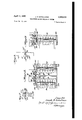
Figures 1 and 9 are diagrammatic illustrations showing a Wheatstone bridge application passing current through delicately balanced control armatures and local motor circuits.
Figures 2 and 3 are a front elevation and a side elevation, largely in diagram, showing a balanced armature construction through which the invention may be applied.
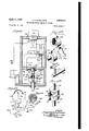
Figure 4 is a perspective view of a structure embodying the diagrammatic material of Figures 1, 2 and 3 and which has been successfully used.
Figure 5 is a top plan view of the structure seen in Figure 4.
Figure 6 is an and elevation of the structure seen in Figure 5.
is moved. The current due to unbalance of the Wheatstone bridge snaps one or other of the snap switches, closing one or other of the load relay circuits 59, 69 through relay coils 6i, 6!. The load circuits fed by the relayscontain each not only the load but means for resetting the center arm of the second potentiometer, with the result that the'snap switch opens and shuts oi! the circuit in which the load is included.
It will be seen that current through the parallel coils 55 and 56 will magnetize both of the poles of the cores alike, since the coils are so wound and connected as to be polarized alike, and will magnetize them reversely according to the direction of current through these parallel coils. For instance, if the current through the parallel coils tends to make both of the core poles south poles, its magnetizing effect will be added to the magnetizing effect at the initial south pole and will be subtracted from the magnetization at the initial north pole and may thus be used greatly to increase the strength of the south pole and greatly to reduce or even to reverse the magnetism at the initial north pole.
Likewise if the unbalance be opposite to that considered above, the current in the parallel coils will greatly increase the magnetization of the north pole of the core and will reduce or reverse the strength of what was initially the south pole. As a result of the above the balanced armature will be tilted (thrown) in clockwise or counter-clockwise direction and by a strength of magnetic reaction much in excess of that which would be available if the current of unbalance through the .parallel coils were depended upon alone to tilt the armature.
The tilt of the armature is used to throw one snap switch or the other against a continuing resistance, thus closing one or other of two relay work circuits is or Gil and coincidently opening the circuit through the series coils.
The coils 6i and 62 in the relay load circuits control, respectively, switches 63 and 54, thus passing current from the mains through connections 65 or 66 to supply forward or reverse motor windings 61 or 68 of a motor 69 shown in Figures 4 and 5. The common return is shown at 10 and limit switches are inserted at Ii and 12 in the forward and reverse connections. In Figure 1 forward and reverse directions of drive of the same motor are intended.
The rotation of the motor, forward or reverse, in addition to its use for any intended service, such as opening or closing a ventilator, is used to throw the central arm H of potentiometer II in the proper direction to a position where the two potentiometers are balanced and the Wheatstone bridge is therefore balanced and at which or approaching which the current through the parallel balanced relay coils becomes low enough to permit automatic opening of that snap switch which had been thrown.
In Figures 4 and an opertive mechanism is shown embodying the structure illustrated diagrammatically in Figures 1, 2 and 3 and in which the motor 69 is the reversing motor which is operated in either direction, responsive to the movement of an arm upon a potentiometer is not there shown, through series and parallel coils upon the relay. The balanced armature operates snap switches 40 and 4| and, through them, suitable load relay coils.
Through ample speed reductions, rotation of the motor armature shaft within cover It is made to turn contact arm ll (efi'ectively it) over potentiometer contacts Ii.
The armature shaft is extended by any suitable coupling, not shown, for connection with any suitable work. In Figures 4, 5 and 6 the various .parts are shown as they have actually been used, except that the first potentiometer is separate from the base.
For convenience in display, the motor unit (Figures 4, 5 and 6) is mounted pon the same base It as the frame of the polarized relay. The first potentiometer and lever for setting it are mounted separately at H. The second potentiometer is mounted upon the upper right or the motor unit in Figures 4 and 5. In these figures the cover 19 for the rotating shaft appears as well as brackets supporting the motor, the motor housing, relays, etc.
In the figures above appear gear box II for the motor housing, limit switches H, 12, extra mount 19 for the motor, by which the motor may be mounted "upside down" as compared with the illustration in Figure 4, if it prove more convenient to the user. Brackets for support of the parts and conduit 00 for wires also appear. Sockets II are shown for outside connection and indicator 92 appears in Figure 4.
The sensitive relay is supported upon a threepoingbearing, having the points 93, 94, II (Figure After the center arm of the first potentiometer has been shifted, the operation of the motor, in whichever direction driven, resets the arm I! so as to balance the potentiometer II with the potentiometer i6, balance the Wheatstone bridge and reduce and finally cut oil the current caused to fiow through the parallel windings by the initial unbalance of the bridge.
The balanced armature is best shown in Figures 2, 3 and 5 in which a mounting bracket 86 (Figure 5) supports return magnetic circuits for the two cores 36 and 31. A three-point suspension is used for the bracket and frame, comprising resilient supports 91, ll, 99, each of which includes spaced resilient (such as rubber) washers between which is gripped a part of the bracket or frame so as resiliently to support the balanced armature, the coils and the switches as a unit. The cores are connected with strips ll, 92 (Figure 2) of magnetizable material which are bent parallel to each other at 93 and 94, and are fastened together back to back. The magnetic circuit thus provided extends to the armature and is there interrupted to provide a pivot support for the armature as seen in Figures 2 and 3.
The strip 95 fits between two snap switches 49 and 4 I. These snap switches are of a type which snap to position by ressure or armature-carried lugs 96 and 91 pressing against operating pins 98 and 99 by which the switches are thrown. The lugs 96 and 91 maintain pressure against the pins in proportion to the current passing through the parallel windings.
Snap switches suitable for this purpose are well known in the art under trade names Micro and Acro."
In each of the switches above, the throw oi the switch takes place by snap action in both directions of throw. In one direction 01' throw, the snap takes place by reason of pressure of a pin movable to an extent of pin throw movement less than snap throw. In all of them, the switch levers automatically reverse when throwing (maintaining) pressure has been removed.
The two cores support spools III, III having Figure 10 is a section of Figure 10 along the line In -m.
Figure 10 is a circuit diagram showing the circuit arrangements in Figure 10.
Figure 11 is a perspective of a contact ring in Figure 10.
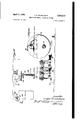
Figure 12 is a diagrammatic view showing thermostatic operation.
There are many functions to be performed where the actual duty is at a distance from the point at which the functions are to be controlled and where it is desirable to complete a limited purpose electrically and then shut off the current. Though these uses are by no means restricted to work upon an airplane, the number and variety of such needs on an airplane are such as to make airplane uses excellent illustrations and the difliculty of performing them on the spot and of following them up to make sure that they have been performed as well as the importance of their satisfactory performance make airplane applications excellent examples.
For instance, many parts are to be moved to a limited or to the total possible extent and subsequently are to be moved back again-such as takes place in the closure and opening of ventilating ports in compartments and where a thermostat switch shifted by reason of change in temperature of a compartment is relied upon to close or open a switch or to slide a switch contact along the surface of a plurality of contacts. The thermostat provides automatic variation of the position of a center arm along a potentiometer scale. I
A similar center arm may be moved by hand along this potentiometer scale. In either event the potentiometer may be used as in Figure l as part of a Wheatstone bridge whose unbalance sets in motion a motor, let us say in clockwise direction, using a thermostatically operated contact arm to engage with the contacts of a resistance or with a single switch or a plurality of switches so as to operate a cooperative potentiometer. Thus, automatically, a second potentiometer may be adjusted to balance the Wheatstone bridge and to cut off the current due to unbalance.
In diagrammatic Figure 1 the following parts are shown:
A Wheatstone'bridge I5 is made up of potentiometers l6 and I! having center arms [8 and I9 dividing the potentiometers into resistance segments 20, 2| for the first potentiometer l6 and 22, 23 for the second potentiometer I1. Current is supplied to the Wheatstone bridge terminals 24, 25 from positive main 25 and negative main 2'! by conductors 28 and 29. The middle arms are intended normally during inaction to be so located along their contact scales that no current tends to flow between them-i. e., in balanced positionbut in Figure 1 are shown as unbalanced.
In the first potentiometer the arm l8 may be thrown about its center 30 by hand or automatically (see Figure 1). One example of automatic operation would be thermostatic operation, by a thermostat 3| (Figure 12) in a com partment 32 whose temperature is to be controlled, a rise or fall in temperature above or below a predetermined standard turning the arm l8 in one direction or the other and unbalancin the system. The amount of unbalance will bear a relation to the extent of movement of the arm and difference in potential is then created between the middle am ll of the first potentiom- 6 eter and the middle arm I! of the second potentiometer. This difierence in potential is applied to a balanced armature control relay 43 through conductors 34 and 35 (see Figure 1).
The control relay as shown comprises a pair of relay cores 35 and 31 magnetically reacting upon a balanced armature 3B pivoted at 39 (see Figure 9). The armature and its relation to the cores are seen in Figures 2 and 3, which also show the magnetic circuit for the cores. Switches 40 and 4| are closed, one at a time, against a resilient opening pressure as the result of tilting movement of the relay. Later the closed switch is allowed to open.
The cores 3!; and 31 are both double wound as indicated diagrammatically in Figures 1, 2 and 3.
Following now Figure 1, the coils 42, 43 of one pair are polarizing coils surrounding the respective cores, connected in series through conductor 44 and supplied with current by conductors 45, 45. This polarizing current passes through switch arms 41, 48 and contacts 49 and 50. These series coils normally give opposite polarity to the terminal poles 5i and 52 of cores 36 and 31. This polarity has been indicated arbitrarily upon the poles in Fig. 9 as north at the left hand and south at the right hand.
By induction the polarization of the cores creates opposite polarity south and north respectively in the ends of the balanced armature so as, in the absence of other magnetization, to hold the armature in balanced position, when it is initially balanced, as it will normally be due to the springs, for example in the snap switches.
The switch arms 41 and 48 (Figures 1 and 9) are capable of making contact at 53 and 54, closing one or other of two relay load circuits.
It is understood that tilting of the soft iron armature about its pivot 39 will open the switch at contact 49 or according to the direction of tilt, and at the same time will close one of the snap switches through contact 53 or 54, the switches being permissibly single pole double throw switches and being of the snap switch variety.
A snap switch is used of a type which snaps open under pressure and will snap back if the pressure he not maintained. It is very desirable that the switches shall not be subject to chatter or other trouble from vibration and that in each direction of movement each switch shall definitely close and definitely open, rather than close and open gradually or uncertainly.
It will be seen that the opening of either switch contact at 49 or 50 opens the series coil circuit as completely and entirely as if the circuit were opened at both these contacts; also that but one contact is closed by swinging movement of the armature, namely contact at 53 or contact at 54.
The second windings, coils 55 and 56, one on each of the cores 36 and 31, are connected in parallel at 51 and 58, and are supplied with current by junction points 34 and 35 connected to arms i8 and I9 so that current from the mains will fiow through these coils in parallel whenever the relative positions of the contacts controlled by arms l8 and I9 unbalance the Wheatstone bridge. In other words, when arm l8 has been adjusted by hand or automatically, the circuit will be unbalanced and current will flow through the :parallel coils about the cores until the potentiometers have again been balanced.
The current will flow in different directions according to the direction in which the arm l8 v 9 insulating ends I02, I33. The spools carry one winding each of the series pair of coils and one winding each of the parallel pair of coils, thus having two windings upon each core.
Plates III4, I between strip II and the magnet return circuit form a convenient support for the pivot upon which the light balanced armature is carried so that the armature will reach over the two poles.
The pivotal pin for the balanced armature Is adjustable lengthwise of the armature, or, alternatively, lengthwise oi the pole pieces in order to make it possible very exactly to balance the armature when it is polarized by the series coils upon or about the control cores. In Figure 7 this adjustment is shown as corresponding with the position of the parts in Figure 2 except that in Figure 2, plates I06, front and back, and screws I01, have been omitted. The screws fit through slots I08 into threaded holes I". The plates carry bearing openings IIO.
In Figure 8 the pivot is carried by a bracket II I fastened to the armature plate II2 by bolt II3 passing through a slot II4 extending longitudinally with respect to the armature. The bracket carries rods II! which serve as the pivots.
As thus constructed, two types of pivot adjustment are available.
If it be desired to maintain the pivot in the center 01' the electrical armature, as by permanent pivot location with respect to the length of the armature, but to adjust the armature bodily with respect to the poles, this can be done by changing the position of the bearing supports with respect to the plates, maintaining equal lengths of armature on one side or the other of the pivot but slightly altering the relative leverages between the armature and the two operating positions 0! the pins by which the switches are thrown.
By slacking bolt II3 the pivot can be adjusted longitudinally of the armature itself, so as to leave unequal lengths of armature on opposite sides of the pivot location, and in this way to balance the armature even if there be slightly unequal strength of core poles.
In the illustration in Figure 3, a guide III in each snap switch supports a pin III which is prevented from falling through the guide, so that the pin is in line with a properly supported diaphragm II8, of any one of the types indicated. The pins for the two snap switches are in line, each with one or other of projections 96, 91 (Figure 2) which are carried by the armature on opposite sides of its center. These projections are supported from the armature body by rods H9, I20 (Figure 2) which are threaded into the arms.- ture and are locked in adJusted position by nuts I2I. By these rods the height of the limit of movement of the snap-switch-operating pins can be adjusted.
It will be understood that all of the adjustments referred to respecting the pivot oi the armature and height of the projections from the armature are very small and make no appreciable difierence in the accurate engagement of the projections with the pins, as seen in Figure 2. The throws of the switch pins are also short.
Figure 9 is a diagrammatic construction corresponding generally to Figure l but having several marked differences from that of Figure 1.
The first is that the armature and cores have not been put into place though it is intended to use an armature and snap switches of the character described in connection with Figures 2 and 3 which snap to an extent greater than the amount moans 10 to which their pins have been pushed but snap backagainwhenthem'essureisreleased.
A second diiierenoe of Figure 9 with respect to Figure 1 is as to the two potentiometers. In Figure 1 they are separated widely to indicate that the first potentiometercan be at any suit able control point and the second potentiometer wherever the motor-let us say-is located. In Figure 9 the potentiometer-s have been brought together into something more nearly approaching the normal Wheatstone bridge though it is the intention still that the second potentiometer neednotbeclosetotheflrstbutcanbespaced from the first to meet the requirement 01' motor location, etc.
The third difierence is that an indicator (signal) light I22 is shown in Figure 9 connected to show when either of the relays is in operation. whereas in Figure 1, while such an indicator (signal) light can be used in the same location, it has not been shown.
A further difference lies in the fact that the Figure 9 form is suited to mechanical operation instead of the hand throwing o! the first potentiometer middle arm for which the Figure 1 form is primarily intended. In this last change a double switch is shown as connected with the throwing mechanism, so that the act of throwing the switch will electrically energize the series and also the parallel windings or coils which will be dead except when the middle arm of this potentiometer is actually being moved. One form of such a switch is shown in Figure 10 with a detail in Figure 11.
As will be seen in Figure 9, double switch contacts I23, I24 energize conductor I25 when pressure is placed upon I23 or I24 to cause movement 0! the middle arm. The middle arm is insulated from conductor I25 but is mechanically connected with it so that this middle arm can be moved by moving either of the operating mechanisms I23 or I24. The conductor I2! is thus energized in either event, causing energization of both series and shunt coils, until opening 01 one or the relay switches at 49 or II interrupts current through the series coils. Resetting of the middle arm of the potentiometer reduces holding pressure upon a snap switch which has been thrown until the switch snaps open.
In Figure 10, one form of operating switch to put into eiiect and make automatic the switch operation occurring at I23 and I 24 is shown (see Figures 10, 10', 10, 10, 10 and 11).
The operating button or mechanical lever for the middle arm of the first potentiometer is not shown in Figure 10 but the shaft connected with it is shaft I23. It is used when the unbalance or the first potentiometer is effected through this shaft I26, electrically conducting pin I21 and an insulating collar I28. The insulation collar carries an electrically conducting annulus I28 shown in Figure 11 whose ends are transversely turned at I30 and I3I so as to present contacts to be closed against the pin. These contacts are given an allowance for play with respect to the electrically conducting pin.
Current is furnished through an amphenol," plug connector I32 having four contacts, one of which is grounded.
The grounded amphenol contact I33 is connected with one side I34 of the first potentiometer for the Wheatstone bridge. A second amphenoP' contact I35 is connected with the .contact I36 of the potentiometer and a third 11 amphenbl contact I31 is connected with the center pin I21 by a contact I38. The fourth amphe'nor contact is connected to the tang I39 01 the annulus I29.
The spacing of the center pin from the contacts I30 and I3I is effected by a spring I40 which is wrapped about a supporting pin HI and extended so that it will bear against the two sides of pin I21 and will also bear against or lie close to a non-conducting stop pin I42 so that the spring will prevent pin I21 from moving either way far enough to make contact with either contact I30 or I3I except as the spring bends.
Threads are shown at I43 by which the potentiometer is mounted to the housing I44.
A signal light I22 is shown supplied with current by conductors I46 and I46. This light is operative when the switch I21, I30, I3I of Figure 10 is turned in either direction and remains operative until the complete control has been effected, i. e. until the snap switch actuated by the polarized relay has returned to open position due to the holding action of relay contacts 83 and 64.
In whichever direction the central shaft is turned the pin I21 is electrically connected with one or the other ofthe contacts I30, I3I of the same annulus to close contact at either I30 or I3I seen in Figure 11.
The cut-out switch at the potentiometer arm in the hand thrown form (Figures 10 and 11) makes it possible to cut the current from the whole system during times when the device is not in operation. The series coils are opened when one relay circuit or the other is closed in order that the parallel coils will have complete control of the polarized relay, improving the accuracy of resetting. This frees the armature from series coil control for return to balanced position when the pressure of the armature against one or other of the switch pins is less than the retracting pressure of the load relay circuit snap switch.
It will be evident that the two potentiometers making up a Wheatstone bridge will not ordinarily be located close together in a construction of this character, as one will be located at the point at which the proposed movement or operation of the load circuit is to be initiated and the other will be located near enough to the motor which is being operated so that the motor itself by its operation will reset the bridge by turning the second potentiometer arm.
It will be seen that use of the switch at the first potentiometer in the hand thrown form of Figure 9 will have another advantage in that while a considerable current may pass through the potentiometer after its arm has been thrown, as soon as the operating arm has been released this current no longer passes through the potentiometer middle arm contacts. Consequently a higher current can be passed through the potentiometer and a larger number of operating points for the middle arm can be provided.
It will be evident that in the automatic form in Figure 12 the second potentiometer may be located physically so closely adjacent to the motor which is being operated (see Figure also) that the motor may be used to swing the second potentiometer middle arm to its compensating position.
In Figure 12 an automatic oil cooling system is shown such as is suitable for protection of oil from over-heating in an airplane oil system.
in juxtaposition to it through which the oil passes in that part of its circulation at which tempera ture correction is to be made. Within the rotary valve is a spiralled bimetallic thermostat 3| whose expansion and contraction cause rotation of a shaft upon which is carried a first potentiometer middle arm I8. Because of the small range of rotary movement available, this arm 'need not travel over an entire potentiometer scale but instead a few potentiometer points may be taken out at intervals and placed close together so as to be within the range desired. Under conditions yielding considerable thermostat travel a correspondingly larger potentiometer range of scale can be covered. In the potentiometer scale shown the end I48 is grounded at I49.
As the rotary valve turns it opens passages for the oil to flow down into and up from the radiator of the oil cooler I41. In the meantime, operation of the first potentiometer arm causes operation of a control relay including relay switch and armature such as are shown in Figures 1, 2, 3 and 8 with the result that one or other of two load relay circuits is closed and current is passed through the forward or reverse windings of motor I50.
As a result of the motor operation, two functions are performed. The one function is that the armature through gearing I5I, I52 operates a screw I53 whose nut I54 throws a ventilating flap I55 to closed, "faired or "full open posi tion, or some fraction of this distance, cooling off the oil in the system. The nut is swiveled to 'the flap.
If the oil be too cool, the action is reversed and the ventilating flap I55 is progressively closed from full open" to faired" position or to closed" position as may be needed, resulting in angular movement of the potentiometer arm I8 either clockwise or counterclockwise as the case may be and resulting in requiring correction by corresponding movement of the second potentiometer arm I9 to balance the Wheatstone bridge.
At the same time that this control of ventilation is taking place the movement of the armature compensates by physical movement of the arm I9 of this second potentiometer so that whether the first potentiometer arm has moved in clockwise or counterclockwise direction, the second potentiometer arm is moved so as to compensate for the movement of the first and to bring the flap to a position which maybe made standard until operation conditions change and to change the position of the flap as may be required to meet new conditions.
Balancing the bridge causes either cooling or heating of the oil in the oil cooler radiator with corresponding reaction upon the spiral thermostat and corresponding retractive movement of the arm of the first potentiometer.
In a given case the action of the second potentiometer arm will not be complete because on its corrective movement it will reach a balancing position with the first potentiometer arm before it is wholly compensated for the initial change in the first potentiometer. In other words, the changes in position of arm I8 because of the corrective effect upon the thermostat will reduce or perhaps in individual cases obviate the corrective movement of the second potentiometer arm.
There may thus be a relative see-saw between the two potentiometer arms, one controlled by the thermostat and the other controlled by the asoaue operating motor in that higher temperature or lower temperature surrounding the thermostat valve will cause resetting of the first potentiometer arm, on either side of the center according to the character of the change of temperature,
shifting the first potentiometer arm to a positionwhich reduces the amount of compensation required.
It will be evident that the actuating shaft in Figure is insulated from but is mechanically connected with the potentiometer shaft in line with it, and the potentiometer shaft in turn is insulated from the potentiometer middle arm but mechanically operates it. .As a result when the actuating shaft is turned in either direction to close one or other of the contacts 3. and ll against the pin the potentiometer shaft is energized but the middle arm of the potentiometer is not energized exceptas it is energized because of the unbalance of the potentiometer.
In Figure 5 is shown a construction by which the sensitivity of the armature may be adjusted. Brass screws I56 pass through the armature plates so that the ends of the screws may be made to engage with the faces of the cores II and 31. The screws are preferably threaded into the plates and are held in adjusted positions by lock nuts I" above the plates. As a result the screws can be backed on so that they have no effect in spacing the armature at its closest point fromthe faces of the poles of the cores or they can be screwed down to space the magnetizable armature from the poles of the cores to varying degrees giving a very delicate adjustment of the amount oi magnetic efl'ect in the cores which is required to throw the armature.
In order that the screws may operate in a greater length of thread, and at the same time giving more magnetizable body to the armature at these points opposite the cores, threaded washers I58 may be screwed to the armatures.
In view of my invention and disclosure variations and modifications to meet individual whim or particular need will doubtless become evident to others skilled in the art, to obtain all or part of the benefits of my invention without copying the structure shown, and I, therefore, claim all such in so far as they fall within the reasonable spirit and scope of my claims.
Having thus described my invention what I claim as new and desire to secure by Letters Patent is:
1. A control relay comprising a centrally pivoted armature, cores on either side of the armature, disposed transversely to the armature on opposite sides of the pivot; and each adapted to pull magnetically on the armature, a polarizing coil around each core, a source of current connected to the polarizing coils in a direction to set up opposing pulls by the coils and cores on the armature, a control coil around each core, reversing control voltage means connected to the control coils in a direction to set up pulls by the control coils and cores on the armature in the same direction, a pair of switches, on operatively connected to the armature for displacement when the armature pivots in each direction from mid position, each switch having a set of contacts open when th armature is in midposition and closedwhen the armature pivots from midposition in one direction, a pair of load relays, a pair of load relay circuits, each including one switch and one load relay, switch means operative when the armature is displaced from midposition in either direction for disconnecting the source from the l4 polarizing coils and operative when the armature is restored to midposition for connecting the source to the polarizing coils.
2. A control relay comprising a centrally pivoted armature, cores on either side of the armaturedisposedtransverselywthearmatureon either side 01' the pivot and each adapted to pull magnetically on the armature, a polarizing coil on each core, a source 01' current connected to the polarizing coils in a direction to set up opposing pulls by the coils and cons on the armature, a control coil around each core, reversing control voltage means conected to the control coils in a direction to set up pulls by the control coils and cores on the armature in the same direction, a pair of double throw switches, one operatively connected to the armature for displacement when the armature pivots in each direction from midposition, each switch having a set or contacts closed when the armature is in midposition and opened when the armature pivots from midposition in one direction and another set or contacts closed when the armature pivots from midpomtion in that direction and opened when the armature returns to midposition, connections interposing the sets of contacts closed when the armature is in midposition and opened when the armature pivots from midposition between the source and the polarizing coils, a pair of load relays, and a pair of load relay circuits each including one of the load relays and one of the sets of contacts closed when the armature pivots from midposition and opened when the armature returns to midposition.
3. In a control relay comprising a centrally pivoted armature, cores on either side of the armature disposed transversely to the armature on either side of the pivot and each adapted to pull magnetically on the armature, a polarizing coil around each core, a source of current connected" to the polarizing coils in a direction to set up opposing pulls on the coils and cores of the armature, a control coil around each core, reversing control voltage means connected to the control coils in a direction to set up pulls by the control coils and cores on the armature in the same direction, spring means urging the armature toward midposition, a pair of double throw switches, one operatively connected to the armature for displacement when the armature pivots in each direction from midposition, each switch having a set oi. contacts closed when the armature is in midposition and opened when the armature pivots from midposition in one direction, and another set of contacts closed when the armature pivots from midposition in that direction and opened when the armature is restored to midposition, a pair of control relays, a pair of control relay circuits each including one of the control relays and one of th sets of contacts closed when the armature pivots from misposition and opened when the armature is restored to midposition, and connections for interposing the contacts closed when the armature is in midposition and open when the armature pivots from midposition between the source and the polarizing coils.
4. A control relay comprising a centrally pivoted armature, cores on either side of the armature disposed transversely on either side of the pivot and each adapted to pull magnetically on the armature, a polarizing coil around each core, a source of current connected to .the polarizing coils in a direction to set up opposing pulls by the coils and cores on the armature, a control coil around each core, reversing control voltage means connected to the control coils in a direction to set up pulls by the control coils and cores on the armature in the same direction, a pair of double throw snap acting switches, one operatively connected to the armature for displacement when the armature pivots in each direction from midposition, each switch having a set of contacts closed whenthe armature is in midposition and open. when the armature pivots from midposition in one direction and another set of contacts closed when the armature pivots from midposition in that direction and open when the armature is restored to midposition, a pair of load relays, a pair of load relaycircuits each including one of the load relays and one of the set", of contacts open when the armature is in midposition and closed when the armature pivots from midposition, and connections interposing the sets of contacts which close when the armature is in mid.- positlon and open when the armature pivots from midposition between the source and the polarizing coils.
5. A control relay comprising a centrally pivoted armature, cores on either side of the armature disposed transversely to the armature on either side of the pivot and each adapted to act magnetically on the armature, a polarizing coil around each core, a source of current connected to the polarizing coils in series in a direction to set up opposing pulls by the coils and cores on the armature, a control coil around each core, reversing control voltage means connected to the control coils in parallel in a direction to set up pulls by the contro coils and cores on the armature in the same direction, a pair of double throw switches, one operatively connected to the armature for displacement when the armature pivots in each direction from midposition, each switch having a set of contacts closed when the armature is in midposition and open when the armature pivots from midposition in one direction, and another set of contacts closed when the armature pivots from midposition in that direction and open when the armature is restored to midposition, a pair of load relays, a pair of load relay circuits each including one of the relays and one of the sets of contacts closed when the armature pivots from midposition and open when the armature is restored to midposition, and connections for interposing the sets of contacts closed when the armature is in midposition and open when the armature pivots from midposition between the source and the polarizing coils.
6. A control relay comprising a centrally pivoted armature,'cores on either side of the armature disposed transversely to the armature on either side of the pivot and each adapted to pull magnetically on the armature, a polarizing coil around each core, a source of current connected to the polarizing coils in series in a direction to set up opposing pulls by the coils and cores on the armature, a control coil around each core, re versing control voltage means connected to the control coils in parallel in a direction to set up pulls by the control coils and cores on the armature in the same direction, a pair of double throw snap switches spring urged toward midposition, one operatively connected to the armature for displacement when the armature pivots in each direction from midposition, each switch having a set of contacts closed when the armature is in midposition and open when the armature pivots from midposition in one direction and another set of contacts closed when the armature pivots from midposition in that direction and open when the armature is restored to midposition, a pair of load relays, a pair of relay circuits each including one of the relays and one of the sets of contacts closed when the armature pivots from midposition and open when the armature is restored to midposition, and connections interposing the sets of contacts closed when the armature is in midposition and open when the armature pivots from midposition between the source and the polarizing coils.
'7. A control relay comprising a centrally pivoted armature, cores on either side of the armature disposed transversely to the armature on either side of the pivot and each adapted to pull magnetically on the armature, a polarizing coil around each core, a source of current connected to the polarizing coils in a direction to set up opposing pulls by the coils and cores of the armature, a control coil around each core, a Wheatstone bridge having balancing arms, a source connected to opposite points of the bridge from the arms, connections from the balancing arms to the control cois in a direction to set up pulls by the control coils and cores on the armature in the same direction, a pair of switches, one operatively connected to the armature for displacement when the armature pivots in each direction from the midposition, each switch having a set of contacts closed when the armature rocks from midpositionand open when the armature returns to midposition, a pair of control relays, a pair of relay circuits each including one of the relays and one of the sets of contacts, and means for disconnecting the polarizing coils from the source when the armature is displaced from midposition.
8. A control relay comprising a centrally pivoted armature, cores on either side of the armature disposed transversely to the armature on either side of the pivot and each adapted to pull magnetically on the armature, a polarizing coil around each core, a source of current connected to the polarizing coils in a direction to set up opposing pulls by the coils and cores on the armature, a control coil around each core, a Wheatstone bridge having balancing arms, a source connected to opposite points ,on the bridge from the balancing arms, connections from the balancing arms of the bridge to the control coils in a direction to set up puls by the control coils and cores on the armature in the same direction, a pair of double throw snap switches spring urged toward midposition connected to the armature for displacement when the armature pivots in each direction from midposition, each switch having a set of contacts closed when the armature is in midposition and open when the armature pivots from midposition in one direction and another set of contacts closed when the armature pivots from midposition in that direction and open when the armature is restored to midposition, a pair of relays, a pair of relay circuits each including one of the relays and one of the sets of contacts open when the armature is in midposition and closed when the armature pivots from midposi- 7 tion and connections interposing the sets of contacts closed when the armature is in midposition and open when the armature pivots from midposition.
9. In a motor control, a control relay comprising a centrally pivoted armature, cores on either side of the armature disposed transversely to the armature on either side of the pivot and each adapted to pull magnetically on the armature, a polarizing coil around each core, a source of current connected to the polarizing coils in a one operatively connected to the armature for displacement when the armature pivots in each direction from midposition, each switch having a set of contacts closed when the armature pivots from midposition in one direction and open when the armature is returned to midposition, means for disconnecting the source form the polarizing coils when the armature is pivoted from midposition, a Wheatstone bridge having balancing arms, a source connected to the bridge at points opposite to the balancing arms, connections from the balancing arms to the control coils in a direction to set up pulls by the control coils and cores on the armature in the same direction, a reversible motor having reverse windings, motor circuits, one including each of the windings and one of the switches, and'mechanical connection between the motor and one of the balancing arms to restore the bridge to balance when the motor is operated.
10. In a motor control, a control relay comprising a centrally pivoted armature, cores on either side of the armature disposed transversely to the armature on either side of the pivot and each adapted to pull magnetically on the armature, a polarizing coil around each core, a source of current connected to the polarizing coils in a direction to set up opposing pulls by the coils and cores on the armature, a control coil around each core, spring means urging the armature toward midposition, a pair of double throw switches, one operatively connected to the armature for displacement when the armature pivots in each direction from midposition, each switch having. a set of contacts closed when the armature is in midposition and open when the armature pivots from midposition in one direction and another set of cohtacts closed when the armature pivots from midposition in that direction and open when the armature is restored to midposition, a Wheatstone bridge having balancing arms, a source connected to opposite points on the bridge from the balancing arms, connections from the balancing arms to the control coils in a direction to set up in the control coils and cores pulls on the armature in the same direction, a pair of relays having load contacts, a pair of relay circuits each including one of the relays and one of the sets of contacts closed when the armature pivots from midposition and open when the armature is restored to midposition, a motor having reverse windings, a pair of motor circuits-each including one of the motor windings and the load contacts of one of the relays, connections placing the sets of contacts closed when the armature is in midposition between the source and the polarizing coils, and mechanical connection between the motor and one of the balancing arms to restore balance.
11. A control relay comprising a centrally pivoted armature, cores on either side of the armature disposed transversely to the armature on either side of the pivot and each adapted to pull magnetically on the armature, a polarizing coil around each core, a source of current connected to the polarizing coils in a direction to set up opposing pulls by the coils and cores on the armature, a controlling coil around each core, a Wheatstone bridge having balancing arms, a
source connected to opposite points on the bridge from the balancing arms, a pair of switches, each operatively connected to the armature for displacement when the armature pivots in one direction from midposition, each switch having contacts closed when the armature pivots from midposition in one direction and, opened when the armature is restored to midposition, a pair of load relays, load circuits each including one of the sets of contacts and one of the relays, an operating member for one of the balancing arms and a switch actuated by the operating member for closing the circuit to the source when the operating member is inactive.
12. A control relay comprising a centrally pivoted armature, cores on either side of the armature disposed transversely to the armature on either side of the pivot and eachadapted to pull magnetically on the armature, a polarizing coil around each core, a source of current connected to the polarizing coils in a direction to set up opposing pulls by the coils and cores on the armature, a control coil around each core, a Wheatstone bridge having balancing arms, a source connected to opposite points on the bridge from the balancing arms, a pair of switches, each operatively connected to the armature for displacement when the armature pivots in one direction from midposition, each switch having contacts closed when the armature pivots from midposition in one direction and open when the armature is restored to midposition, a pair of load relays, load circuits each including one of the sets of contacts and one of the load relays, an operating member for one of the balancing arms, a switch actuated by the operating member for closing the circuit to the source when the operating member is manipulated and opening the circuit to the source when the operating member is inactive.
13. In a control circuit, a Wheatstone bridge having balancing arms, an operating member for one of the balancing arms, a source of current connected to opposite points of the bridge from the balancing arms, a switch actuated by the operating member for closing the circuit to the source when the operating member is manipulated and opening the circuit when the operating member is inactive, and automatic means including a relay and a motor operatively interconnected for restoring balance to the operating arms.
14. In a control circuit, a Wheatstone bridge having balancing arms, an operating member for one of the balancing arms, a source of current connected to opposite points of the bridge from the balancing arms, a switch actuated by the operating member for closing the circuit to the source when the operating member is manipulated and opening the circuit when the operating member is inactive, automatic means including a relay and a motor operatively interconnected for restoring balance to the operating arms and connections from the source to the opposite points of the bridge for holding current on the bridge during a period of unbalance notwithstanding that the switch actuated by the operating member may open.
15. In a motor control, a control relay comprising a centrally pivoted armature, cores on either side of the armature disposed transversely to the armature on either side of the pivot and each adapted to pull magnetically on the armature, a polarizing coil around each core, a source of current connected to the polarizing coils in a direction to set up opposing pulls by the polariz-' ,other set of contacts closed when the armature pivots from midposition in that direction and open when the armature is restored to midposition, a Wheatstone bridge having balancing arms, a source connected to opposite points on the bridge from the balancing arms, connections from the balancing arms to the control coils in the direction to set up in the control coils and cores pulls on the armature in the same direction, a pair of relays having load contacts, a pair of relay circuits each including one of the relays and one of the sets of contacts closed when the armature is pivoted from midposition and open when the armature is restored to midposition, a motor having reverse windings, a pair of motor circuits each including one of the motor windings and the load contacts of one of the relays, connections placing the sets of contacts closed when the armature is in midposition between the source and the polarizing coils and a mechanical connection between the motor and one of the balancing arms to restore balance.
JOSEPH H. SCHELLMAN.
namnnncns crrnn file of this patent:
UNITED STATES PATENTS Number Name Date 959,787 Nicholson -1.-- May 31, 1910 1,388,632 Dean Aug. 23, 1921 1,979,588 Vreeland Nov. 6, 1934 2,025,218 Reinken Dec. 24, 1935 2,025,292 Lockett Dec. 24, 1935 2,062,345 Wilhelm Dec. 1, 1936 2,108,775 MacGeorge Feb. 15, 1938 2,178,289 Snavely Oct. 31, 1939 2,232,077 Rosecky Feb. 18, 1941 2,252,761 Estes Aug. 19, 1941 2,254,039 Kovalsky Aug. 26, 1941 2,273,275 Kutzler et al. Feb. 17, 1942 2,277,653 Evans Mar. 24, 1942 2,340,004 McGroth Jan. 25, 1944 2,371,732 Bristol Mar. 20, 1945 2,404,227 Hall July 16, 1946 FOREIGN PATENTS Number Country Date 342,354 Great Britain Feb. 2, 1931
Priority Applications (1)
| Application Number | Priority Date | Filing Date | Title |
|---|---|---|---|
| US513551A US2503513A (en) | 1943-12-09 | 1943-12-09 | Wheatstone bridge follow-up system |
Applications Claiming Priority (1)
| Application Number | Priority Date | Filing Date | Title |
|---|---|---|---|
| US513551A US2503513A (en) | 1943-12-09 | 1943-12-09 | Wheatstone bridge follow-up system |
Publications (1)
| Publication Number | Publication Date |
|---|---|
| US2503513A true US2503513A (en) | 1950-04-11 |
Family
ID=24043750
Family Applications (1)
| Application Number | Title | Priority Date | Filing Date |
|---|---|---|---|
| US513551A Expired - Lifetime US2503513A (en) | 1943-12-09 | 1943-12-09 | Wheatstone bridge follow-up system |
Country Status (1)
| Country | Link |
|---|---|
| US (1) | US2503513A (en) |
Cited By (4)
| Publication number | Priority date | Publication date | Assignee | Title |
|---|---|---|---|---|
| US2688458A (en) * | 1951-03-27 | 1954-09-07 | Exact Weight Scale Co | Classifier and controller for weight-checking devices |
| US2693558A (en) * | 1951-04-03 | 1954-11-02 | Ward Leonard Electric Co | Electric follow-up motor control apparatus |
| US2880985A (en) * | 1953-09-03 | 1959-04-07 | Koehring Co | Load-measuring device |
| US3453510A (en) * | 1964-04-30 | 1969-07-01 | Robertshaw Controls Co | Linear and rotary direct current stepping motors and control system |
Citations (17)
| Publication number | Priority date | Publication date | Assignee | Title |
|---|---|---|---|---|
| US959787A (en) * | 1908-07-22 | 1910-05-31 | Lloyd Carlton Nicholson | Circuit-controlling apparatus. |
| US1388632A (en) * | 1919-02-10 | 1921-08-23 | Peter P Dean | Means for regulating the flow of fluids |
| GB342354A (en) * | 1929-11-02 | 1931-02-02 | Stanley Jaffa Harley | Electric distant controlling system |
| US1979588A (en) * | 1929-07-24 | 1934-11-06 | Frederick K Vreeland | Remote control for radioreceivers |
| US2025292A (en) * | 1933-10-23 | 1935-12-24 | Cutler Hammer Inc | Circuit controlling device |
| US2025218A (en) * | 1929-09-26 | 1935-12-24 | Fed Telegraph Co | Remote control apparatus for radioreceivers |
| US2062345A (en) * | 1934-09-27 | 1936-12-01 | Henry A Wilhelm | Electrical controlling device |
| US2108775A (en) * | 1935-10-08 | 1938-02-15 | Automatic Temperature Control Co Inc | Relay |
| US2178289A (en) * | 1937-05-07 | 1939-10-31 | Union Switch & Signal Co | Electrical relay |
| US2232077A (en) * | 1940-05-20 | 1941-02-18 | Cutler Hammer Inc | System of circuit control |
| US2252761A (en) * | 1938-05-06 | 1941-08-19 | Western Union Telegraph Co | Relay |
| US2254039A (en) * | 1938-01-13 | 1941-08-26 | Westinghouse Electric & Mfg Co | Voltage regulator relay system |
| US2273275A (en) * | 1939-11-20 | 1942-02-17 | Honeywell Regulator Co | Motor control system |
| US2277653A (en) * | 1939-07-20 | 1942-03-24 | Cutler Hammer Inc | Electromagnetic relay |
| US2340004A (en) * | 1941-11-15 | 1944-01-25 | Honeywell Regulator Co | Control system |
| US2371732A (en) * | 1942-08-27 | 1945-03-20 | Leeds & Northrup Co | Electrical control system |
| US2404227A (en) * | 1943-01-08 | 1946-07-16 | Gen Electric | Electromagnetic control apparatus |
-
1943
- 1943-12-09 US US513551A patent/US2503513A/en not_active Expired - Lifetime
Patent Citations (17)
| Publication number | Priority date | Publication date | Assignee | Title |
|---|---|---|---|---|
| US959787A (en) * | 1908-07-22 | 1910-05-31 | Lloyd Carlton Nicholson | Circuit-controlling apparatus. |
| US1388632A (en) * | 1919-02-10 | 1921-08-23 | Peter P Dean | Means for regulating the flow of fluids |
| US1979588A (en) * | 1929-07-24 | 1934-11-06 | Frederick K Vreeland | Remote control for radioreceivers |
| US2025218A (en) * | 1929-09-26 | 1935-12-24 | Fed Telegraph Co | Remote control apparatus for radioreceivers |
| GB342354A (en) * | 1929-11-02 | 1931-02-02 | Stanley Jaffa Harley | Electric distant controlling system |
| US2025292A (en) * | 1933-10-23 | 1935-12-24 | Cutler Hammer Inc | Circuit controlling device |
| US2062345A (en) * | 1934-09-27 | 1936-12-01 | Henry A Wilhelm | Electrical controlling device |
| US2108775A (en) * | 1935-10-08 | 1938-02-15 | Automatic Temperature Control Co Inc | Relay |
| US2178289A (en) * | 1937-05-07 | 1939-10-31 | Union Switch & Signal Co | Electrical relay |
| US2254039A (en) * | 1938-01-13 | 1941-08-26 | Westinghouse Electric & Mfg Co | Voltage regulator relay system |
| US2252761A (en) * | 1938-05-06 | 1941-08-19 | Western Union Telegraph Co | Relay |
| US2277653A (en) * | 1939-07-20 | 1942-03-24 | Cutler Hammer Inc | Electromagnetic relay |
| US2273275A (en) * | 1939-11-20 | 1942-02-17 | Honeywell Regulator Co | Motor control system |
| US2232077A (en) * | 1940-05-20 | 1941-02-18 | Cutler Hammer Inc | System of circuit control |
| US2340004A (en) * | 1941-11-15 | 1944-01-25 | Honeywell Regulator Co | Control system |
| US2371732A (en) * | 1942-08-27 | 1945-03-20 | Leeds & Northrup Co | Electrical control system |
| US2404227A (en) * | 1943-01-08 | 1946-07-16 | Gen Electric | Electromagnetic control apparatus |
Cited By (4)
| Publication number | Priority date | Publication date | Assignee | Title |
|---|---|---|---|---|
| US2688458A (en) * | 1951-03-27 | 1954-09-07 | Exact Weight Scale Co | Classifier and controller for weight-checking devices |
| US2693558A (en) * | 1951-04-03 | 1954-11-02 | Ward Leonard Electric Co | Electric follow-up motor control apparatus |
| US2880985A (en) * | 1953-09-03 | 1959-04-07 | Koehring Co | Load-measuring device |
| US3453510A (en) * | 1964-04-30 | 1969-07-01 | Robertshaw Controls Co | Linear and rotary direct current stepping motors and control system |
Similar Documents
| Publication | Publication Date | Title |
|---|---|---|
| US2285540A (en) | Control system | |
| US1715750A (en) | Control system | |
| US2320881A (en) | Control apparatus | |
| US2503513A (en) | Wheatstone bridge follow-up system | |
| US1694237A (en) | Control system | |
| US3261963A (en) | Automatic electric fluid heating apparatus | |
| US2861233A (en) | Servomechanism having unlimited servoing range | |
| US2217254A (en) | Means for automatic control of aircraft | |
| US2287045A (en) | Control apparatus | |
| US2488780A (en) | Motor control follow-up system | |
| US2539089A (en) | Dual range automatic temperature control system | |
| US2127680A (en) | Temperature control mechanism | |
| US2313079A (en) | Condition control | |
| US1877605A (en) | Opposed motor control system | |
| US2366387A (en) | Modulating condition responsive switch | |
| US2170072A (en) | Control system | |
| US2357205A (en) | Measuring ani | |
| US2545390A (en) | Electrical control system | |
| US1989972A (en) | Proportioning control system | |
| US2028110A (en) | Remote control system | |
| US2089826A (en) | Electric heating system control | |
| US2643354A (en) | Automatic pilot for mobile craft | |
| US2460497A (en) | Automatic regulating system | |
| US2006306A (en) | Apparatus and method for temperature regulation | |
| US2278113A (en) | Galvanometer contact device |