US2496119A - Traction device for automotive vehicles - Google Patents
Traction device for automotive vehicles Download PDFInfo
- Publication number
- US2496119A US2496119A US652618A US65261846A US2496119A US 2496119 A US2496119 A US 2496119A US 652618 A US652618 A US 652618A US 65261846 A US65261846 A US 65261846A US 2496119 A US2496119 A US 2496119A
- Authority
- US
- United States
- Prior art keywords
- concave
- tire
- base
- traction
- transverse
- Prior art date
- Legal status (The legal status is an assumption and is not a legal conclusion. Google has not performed a legal analysis and makes no representation as to the accuracy of the status listed.)
- Expired - Lifetime
Links
Images


Classifications
-
- B—PERFORMING OPERATIONS; TRANSPORTING
- B60—VEHICLES IN GENERAL
- B60B—VEHICLE WHEELS; CASTORS; AXLES FOR WHEELS OR CASTORS; INCREASING WHEEL ADHESION
- B60B39/00—Increasing wheel adhesion
- B60B39/02—Vehicle fittings for scattering or dispensing material in front of its wheels
- B60B39/12—Vehicle fittings for scattering or dispensing material in front of its wheels the material being sheet-like or web-like
Definitions
- This invention relates to devices for providing traction for the wheels of automotive vehicles, when stalled because of ice, snow. mud, etc. on the roadway.
- That lugs or the likeI of prior devices as referred to have been designed so that if they give continuous traction they must be so close together, successively, as the tire rolls over them, as to become clogged or illled-over with snow, ice, mud, etc., and so as to render them ineffective unless cleaned out by hand.
- Fig. 1 is a top plan view of a device embodying the invention made in a single piece as a metal casting; 1
- Fig. 2 is a longitudinal sectional view from the plane 2 2 ofFig.. 1;
- Fig. 3 is an end view from' the direction of the arrow 3 of Fig. 1;
- Fig. 4 is a sectional view from the plane 4 4 of Fig. 2;
- Fig. 5 is a bottom plan view of the device of Fig. l;
- Fig. 6 is a top plan view of a plurality of devices similar to that of Fig-1 but modified to adapt them to be coupled together into a continuous trackway as shown;
- Fig. 7 is a longitudinal sectional view from the plane 'l-l of Fig. 6;
- Fig. 8 is a fragmentary elevational View taken in the direction of. the arrow 8 of Fig. 6;
- Fig. 9 is a top plan view of another form of the device similar to that of Fig. 1 but as made from sheet metal;
- Fig. 10. is a longitudinal sectional view taken from the plane i il-I 0 of Fig. 9; f
- Figs. il, 12,. and 13 aresectional views taken from the planes II-H, I2-I2, and 3-I3 re ⁇ spectively oi Fig. 9;.
- Figs. 14', 15, and 16 are views similar to Figs. 11, i2, and ll?l respectively, but illustrating a modication.;
- Fig. 17 is atop 'plan view'oi a plurality of devices similar to that of Fig. 9 but modified to adapt them to be coupled together into a con tinuous trackway as shown;
- Fig. 2l is a top plan view showing in solid line, ⁇
- Fig. 22 is a sectional view from the plane 22-22 of Fig. 21;
- Fig. 23 is a broken sectional view from the plane 23-23 of Fig. 21;
- Figs. 2l and 22 show in brokenlline how a number of the embodiments of Figs. 21 and 22 may be coupled together longitudinally.
- a dat base or elongated bottom generally rectangular in plan, having side walls 2 and 3 extending upwardly therefrom.
- the bottom I at its 4opposite ends terminates in edges 4 and 5, and these end edges are cut back or recessed to provide concave arcuate end edge portions 6 and 1 preferably of circular contour; and at .theupper side of these arcuate recesses 9 and 1 the metal is formed to provide relatively sharp or angular corner edges 8 and 9.
- a plurality such asfive ns or fln walls, I0 to I4 inclusive, are cast integral with the bottom I, extend upwardlytherefrom and transversely thereof and join integrally with the side walls 2 and 3.
- the lupper edges of Vthese fins are upwardly concave as indicated in Figs. 3 and 4, and are preferably vof circular contour, and these arcuate upper ⁇ edges are serrated as shown at I5 to I8 for the fins I0,- II, I3, and I4.
- nsln to I4 inclusive have the said upwardly concave serratededges but inasmuch as the serrated edges may in some cases if desired be omitted from the central fin I2, they have not been shown in the drawing on that n.
- the said fins .I0 to I4 are of different heights, this difference being provided preferably by utilizing different radii ⁇ for the respective arcuate upper edges. As shown in Fig.' 2 and indicated in Fig. 3 the end tins I0 and I4 are the lowest, the fins II and I3 are higher than the fins I9 and I4 and the middle 'n I2 is the highest of them all, for a purpose to be described.
- transverse calk 25 near one end of the device having a downwardlysha'rp edge 25; and a similar transverse calk 21 'having a similar across the device as shown in Fig. 1 and indicated 4 twoflongitudinally extending 65 the wheel.' sharp edge 28, these calks extending transversely 4 calks 29 and 30 disposed adjacent to the side edges of the base extending downwardly therefrom and having sharp downward edges 3I and 32, see Fig. 4.
- these four calks 25, 21, 29, and 39 constitute what may be referred to as a fence on the bottom of the device enclosing therewithin a flat surface space 33 for a purpose to be referredv to. r 'f
- Figs. 19 and 20 In the Operation of the device of Figs. 1 to 5, reference may be made to Figs. 19 and 20.
- an automobile wheel 34 having a rubber tire 35 rests upon a slippery but otherwise unobstructed roadway surface 36.
- the device as described above is presented to the tire 35 by the operator and in doing so he slides the calk edge 26 along the ground and rocks the device counterclockwise as viewed in the figure until the said sharp corner edges 8 and I9 engage the tire.
- edges because of their concave form embrace the rounded tire 35 and engage it on a considerable angular extent therearound.
- the device may be forced inwardly so as to make the contact engagement of the tire with the concave edges 8 and I9 a -gripping engagement.
- Either end of the device may thus beV presented to the tire optionally; the corner edges 9 and 23 functioning the same asA the-said corner edges 8 and I9.
- v l 1j When torque is'xapplied to the wheel in the clockwise ⁇ .direction of Fig. 19, the. ⁇ gripplng engagement therewith of thefconcave sharp corner edge 8 and ⁇ the concave serrated sharp corner edge I9 develops accordingly great traction. and
- the device When the vehicle is stalled by a wheel in deep snow or mud as referred'fto, the device may be presented to the wheeias ⁇ s'how'n in Fig. 20.
- the snow or lmud may be sooped'out to provide an inclination 31 upon which the device may be placed, and the device ispushed downwardly toward the tire until the sharp serrated corner edge I9 on the fin I0 eg'a'ges'the tire, and preferably also until the concave'serrted corner edge 2n on the second fin'lI engages v ⁇ the tire.
- Both fins embrace therounded setiori'of'the tire as referred to. 'I'he traction'thus developed will cause the wheel to roll successively over ⁇ the ns as it climbs up the inclination 'over the device.
- mud. .particularly ⁇ as in the case of Fig; 20 may fall into the device and iill up the spaces between the adjacent fins and render them ineiective for gripping engagement with the tire. This can be avoided by spacing the ns farther apart; but then they are not close enough together to insure continuous traction in going from one to the other. In the present device, this diiculty has been overcome by making them successively higher toward the middle of the device, so that notwithstanding that they are disposed relatively far apart, to prevent excessive snow and mud collection as referred to the tire upon rolling over one nn makes early engagement with the next one at least until the tire has rolled to the longitudinal middle of the device, after which the momentum gained by the vehicle will reduce the need for artificial traction.
- At least two such devices will be stored and carried in the vehicle, because if one slipping wheel is given artificial traction by the device, the other wheel may begin to slip and should likewise be given artificial traction.
- the device In this use of the device, it is turned upside down as indicated in Fig. 5 and laid upon the ground; and the jack base is placed upon the iiat bottom surface 33, particularly when the ground is soft and the base might sink into the ground, or when the ground is slippery or uneven and the base of the jack might slip laterally.
- the base of the jack When the base of the jack is placed on the surface 33, the calks surrounding this space in the nature ofa fence as referred to, prevents slipping of the jack base on the device even if the device cannot be horizontally placed with the said surface horizontal.
- a single unit length of the device such as that shown in Figs. 1 to 5 may not be sufficient. It may be necessary to provide artiiicial traction for the vehicle wheel over a greater distance before the wheel will come into contact with a roadway surface on which it will no longer slip.
- Figs. 6, 7, and 8 is 'illustrated a modification of the device of Figs. 1 to 5 by which a number of said devices may be coupled together to provide a continuous trackway either on level slippery ground or upon an inclined snow or mud bank.
- Figs. 6 to 8 there is shown at 38 and 39 and indicated at 40 three such units having all of the operating features of the single unit above described although the said serrations on the transverse ins have been omitted for the sake of simplification of the drawing, and having the following additional features.
- the side walls 2 and 3 are bent inwardly as at 4I and 42 so that the forward ends ⁇ 4
- a pair of lugs 43 and 44 are formed integral with the side walls 2 and 3 respectively and with the bottom I, and theend portions 4I and 42 are s 6 provided on'the'irundersides with the recesses 45 and 45 providing in effect hooks 4l and 48 which may be hooked over the projections 43 and 44' to couple the forward hooked end of one unit with the rearward end of another unit.
- the principal dillerenc'e is that the device here shown can be fabricated Afrom sheet metal,
- the base 49 and side walls 55 and Si are rst formed integrally by cutting and bending or press forming operationsfinto a' trough-like body.
- transverse iins. which in this case are shown at I52 to 56 inclusive, sheet metal pieces are formed and welded at their ends as indicated -at 51-to the'inner wall of the sides 59 and 5l: To'providethe upwardly concave edges on the'ns the' pieces 52 to 56 .may rst be formed from straight bar stock-.or
- the fin 52 is shown as having an intermediate horizontal upper edge portion 58; and at each side thereof inclined portions 59-'59.
- the tire being resilient, will, as it rolls up on the fin 52 yield and engage all three edge portions 58 and 59-59 and thus grip the iin.
- These edge portions being of dif# ferent inclination tend to bite into the resilient tire more effectively than if these edges were all disposed ona continuous smooth concave arc, and therefore the different inclinations of these edge portions function to produce generally the same effect as serrations.
- ns are indicated at 59, El, and 62 as welded at their ends to the side walls 59 and 5! and suspended thereby; and the ns are formed from rectangular or square section bar stock twisted so that the edges of the twisted stock as at 63-63 provide teeth or serrations on the upper sides of the fins.
- , and 62 beforebeing welded, are bent to be concave on their serrated upper sides as shown in the drawing, and each, lproceeding from the end of the device is welded on at a higher elevation than the one preceding it to cause the ns to be successively higher as referred to.
- pieces of angle section steel 64 and 65 are welded to the underside of the base 49.
- Figs. 17 and 18 is shown, to smaller scale, a modification of the sheet metal form of Figs. 9 to 13, by which a number of units may be coupled together to provide an elongated trackway.
- each unit for example the side walls 69 and 10 of the unit 61 instead of being parallel, as in Fig. 9, are inclined o r tapered toward each other so that the forward end of the unit is, in its overall dimension, narrower than its rearward end, whereby the forward end of one unit may be inserted into the rearward end of the unit ahead of it.
- each unit At the rearward end of each unit, a pair of posts 1l and 12 are welded to the base of the unit at points adjacent the side walls thereof, and project upwardly therefrom. At the forward end of each unit a pair of perforations 13 and 14 are provided in the base of the unit.
- transverse fins of these units may be like those of Figs. 11 to 13 or of those of Figs. 14 to 16 as may be desired, and as will be understood, the type of fins shown in Figs. 11 to 13 being illustrated in Figs. 17 and 18.
- Figs. 21 to 23 is illustrated another embodiment of the invention, in general similar to that of Figs. 6, 7, and 8, inasmuch as the device is made from cast metal; and a brief description thereof will suffice.
- a fiat base or bottom 15 has side walls 16 and 11 between which are ns 18 to 82; the fins be- 82, being the lowest, the iin 80 at the middle being the highest, and the fins 19 and 8
- the upper edges of the side walls 16 and 11 are serrated having concavities as at 83-83 between pairs of fins; whereby, as will be apparent, when one of the devices is turned upside down and laid upon another like device, for packaging or transportation, they will to a considerable degree nest with each other and occupy less space.
- the base 15 extends at its opposite ends beyond the end fins 1B and 82; and as at 84 and 85; and has concave edges 86 and 81 for the tire engaging purposes described hereinbefore.
- are provided similar to those described for Figs. 1 and 2, and for a like purpose, and the transverse calks 90 and 9
- each device for example the left end'of the device as viewed in Figs. 21 vand 22, laterally outwardly open hook devices 94 and 95 are provided, L-shape as viewed from above and comprising each a side wall 96 generally parallel to the side walls 19 and 'l1 of the device, offset inwardly laterally therefrom; and integral with the end iin 18 and with the portion 84 of the base extending beyond the end fin, and having outwardly laterally extending hook portions 91-91.
- hook devices 98-98 are provided, also L-shape in plan, and having hook side walls 99-99 formed by extensions of the side walls 'I6-11, and having inwardly laterally extending hook portions itil-99; and extensions of the base 15 as at ⁇ 0i-I0! integral with the end iin 82' and with hook portions U19-
- the left end of one unit device may be hooked into the right end of a like unit shown in solid line, to couple one unit to another longitudinally, and 'this may be' repeated for any desired number of units to constitute a trackway of any length for the purposes described hereinbefore.
- the hook device at the left end of one unit is disposed above the hook device at the right endof the other unit and then lowered into the latter.
- a vehicle wheel in rolling toward the right over the two such coupled unitsA and in rolling from one to another, will not'be able by its weight to uncouple the units because the left hand hook devices rest upon the said floors IDI- IUI of the right hand hook devices.
- the hook devices being of considerableA longitudinal extent at both ends of the unit, allows lateral lost motion by which, as shown in Fig. 21, a succession of coupled units may be disposed upon a curve; and as shown in Fig. 22, a series of coupled units may follow an upward inclination; the purposes of which will be clear from the foregoing description of other forms.
- an elongated flat base wall having opposite spaced-apart side walls; an end of the base wall being recessed to provide thereon a transverse concave arcuate edge conforming generally to theuproilleg a vehicle 4tire tread and the arcuate edhneing ⁇ at.s'ulzstantially right 4angles to the base; a' transverse group .gripping .the said end-1in; -this'everal fins proceedingsuc,
- an elongated base Wall having opposite spaced-apart side walls; and end of the base Wall being recessed to provide thereon a transverse concave arcuate edge conforming generally to the prole of a vehicle tire and the arcuate edge being at substantially right angles to the base; a transverse ground gripping calk on the underside of the base Wall near the recessed end; a plurality of transverse longitudinally spaced apart ns, projecting upwardly from the base Wall and each having an upwardly concave edge conforming generally to the prole of a Vehicle tire tread; the concave edge of the end n nearest the end of the ybase Wall being inwardly of the concave edge on the end of the base Wall.
- an elongated channel-form base longitudinally spaced, transverse ns projecting upwardly from the channel web, and having upwardly concave upper edges conforming generally to the prole of a vehicle tire tread; a concave recess in an end of the channel web conforming generally to the prole of a vehicle tire tread and the recess having an edge substantially at right angles to the base; the concave upper edges of the lns being successively farther from the channel web proceeding from the recessed end thereof; and a transverse calk on the underside of the channel web near its recessed end.
- an elongated channel-form base comprising longitudinally spaced, transverse fins projecting upwardly from the channel web, and having upwardly concave upper edges conforming generally to the prole of a Vehicle tire tread; a concave recess in an end of the channel web conforming generally to the pronle of a vehicle ,tire tread and vthe recess having ari-edge' substantially at right angles to the base; and a ⁇ vtransverse callg, on the undersideof the channel web nea-r its recessed end.
- a traction device for pneumaticallyftired ve.'- hicle wheels comprising, an elongated sheet inetail channel; a plurality of transverse. elements in the channelspacedapart longitudinally of the chain- .nel; the. transverse elements having upwardly concave edgeportlons .con forming generally to the profile of v a Vvehicle tire tread disposed suc'.- cessively farther from the. channel web; proceed- .ing from an' end thereof.; ⁇ aneud ofthe channel webhaving 'a concaverecess therein .conforming eenerally .to the profile of a'vehiclc tire tread and the recess having an edge.
- a traction device for pneumatically-tired vehicle wheels comprising an elongated sheet metal channel; a plurality of transverse elements in the channel spaced apart longitudinally of the channel; the transverse elements having upwardly concave edge portions conforming generally to the prole of a vehicle tire tread disposed successively farther from the channel web, proceeding from an end thereof; an end of the channel web having a concave recess therein conforming generally to the profile of a vehicle tire tread and the recess having an edge substantially at right angles to the base; a transverse ground gripping calk of Ilange-section metal Welded to the under side of the web near the recessed end thereof; the said transverse elements comprising lengths of bar stock of polygonal section twisted about the longitudinal axis, bent into arcuate form and Welded at their ends to the channel flanges.
- a traction device for pneumatically-tired vehicle Wheels comprising an elongated sheet metal channel; a plurality of transverse elements in the channel spaced apart longitudinally of the channel; the transverse elements. having upwardly concave edge portions conforming generally to the prole of a vehicle tire tread; an end of the channel web having a concave recess therein conforming generally to the profile of a vehicle tire tread and the recess having an edge substantially at right angles to the base; a transverse ground gripping calk of iiange-section ymetal welded to the underside of the web near the recessed end thereof; the said transverse elements comprising lengths of bar stock of polygonal section twisted about the longitudinal axis, bent into arl1 cuate form and welded at their ends to the channel flanges.
- a generally rectangular unit comprising a channel form base, and a plurality of upwardly concave transverse ns in the channel; projection means at the rectangular corners of the unit at one end, and projection receiving means at the rectangular corners at the otherrend; the projection means being engageable .with the projection receiving means of a like unit, to couple the two units together to form a tractionf trackway.
- a generally rectangular unit comprising a channel form base, and a plurality lof transverse upwardly concave iins in the channel;l hooks at the rectangular corners of the unit at one end; hook receptacles at the ⁇ rectangular .corners at the other end; the hooks of the unit being engageable with the hook receptacles of a like unit to couple the units together longitudinally to form a traction trackway.
- anelongated base wall havingv opposite spaced-apart side walls; an end of the base wall being recessed to provide thereon va transverse concave'arcuate edge conforming generally to the proboard onfY a vehicle tire tread and the arcuate edge being at' substantially right angles to the, base formed to provide aty the upper side ofthe edge a sharp corner; a transverse ground gripping call: on the underside yof the base wall near the'recessed end; a plurality of transverse longitudinally spaced apart fins, projecting upwardly from the base wall and each having an upwardly concave edge conforming generally to the profile of a vehicle tire tread; the concaveedge of the end iin nearest the end of the base wall being inwardly of the concave edge .on the end of the base wall and formed to provide at the side of the edge a sharp corner; the several fins, proceeding successively from the end fin toward the other end ofthe base wall having theiry conca
Landscapes
- Engineering & Computer Science (AREA)
- Mechanical Engineering (AREA)
- Tires In General (AREA)
Description
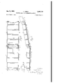
Jan. 3l, 1950 F. cEsEN 2,496,119
TRACTION DEVICE EUR AUTOMOTIVE VEHICLES Fil-ed Maron 7, 194e 4 Sheets-Sheet 1 Jan. 3l, 1950 F. cEsi-:N
TRAOTION DEVICE FOR AUTOMOTIVE VEHICLES 4 Sheets-Sheet 2 Filed March 7, 1946 /NVE/VTOR Fran/f C65@ O B7 /1/7 i WJ Jan 31, 1950 F, QESEN 2,496,119
TRACTION DEVICE FOR AUTOMOTIVE VEHICLES HTTOA/E Y Jan, 31, i950 F. cEsl-:N 2,496,119
TRACTION DEVICE FOR AUTOMOTIVE VEHICLES Filed March 7, 1946 4 Sheets-Sheet 4 Patented Jan. 3l, 1950 OFFICE TRACTION DEVICE FOR AUTOMOTIVE n VEHICLES Frank Cesen, Cleveland, Ohio Application March 7, 1946, Serial No. 652618 (Cl. 23S-44) 12 Claims. l
This invention relates to devices for providing traction for the wheels of automotive vehicles, when stalled because of ice, snow. mud, etc. on the roadway.
Because of the differential gearing commonly provided between the engine and the two drive wheels of an automotive vehicle, if either Wheel rests upon a slippery roadway, it may be caused to slip and rotate and prevent propulsion of the vehicle by the other wheel; or if the vehicle is blocked by deep snow or mud the traction required of the driving wheels may be greater than can be developed on the slippery roadway and one or the other of the-drive wheels will slip. In either event the vehicle will be stalled unless the traction is articially increased.
Various devices have been proposed to provide such artiiicial traction; and amongV these are devices comprising a short piece of trackway which can be carried inr the vehicle and when needed may be laid on the roadway in front of the wheel and upon and over which the wheel may roll; and the present invention relates to devices of this type.
Such devices as heretofore proposed have a number of defects which have rendered them iinpracticable and unsatisfactory.
Among these defects of prior devices are:
vThat the rounded. periphery of the rubber tire ofthe wheel which` must engage and grip and ride up on the device, has Contact withthe device on only a small point or zone on the tire, insuiiicient in contact area to develop enough driving traction to start movement of the vehicle unless the tire is iirst jacked yup high enough from the roadway to permit putting the device under the tire That lugs or the like provided on prior devices in the attempt to insure traction between the tire and the device likewise do not afford suihcient traction-developing grip with the tire;
That lugs or the likeI of prior devices as referred to have been designed so that if they give continuous traction they must be so close together, successively, as the tire rolls over them, as to become clogged or illled-over with snow, ice, mud, etc., and so as to render them ineffective unless cleaned out by hand.
That prior devices oi this type have had to be of. short length to be conveniently stored and carried in the vehicle and often this is not enough to enable the wheels to roll clear of' the diiliculty and out onto the solid traction developing part ofthe roadway.v
It isr among the objects of this invention vto provide generally adeviceoi' this type in which these and other objections to prior devices are overcome.
Other objects are:
To provide a device of this class of unit length, long enough for ordinary occasions, but which may be quickly and conveniently coupled to other like units to provide a continuous trackway of greater length;
To provide a device of the class referred to having roadway gripping lugs or teeth on its underside to prevent slipping of the device out of position in the use described; and which device when laid upside down presents a iiat surface as a base for a vehicle jack; and the said road gripping lugs constitute a fence like retainer to prevent the jack base from slipping off of the device.
Other objects will be apparent to those skilled in the art to which the invention appertains.
The invention is fully disclosed in the following description taken in connection with the accom# panying drawing, in which:
Fig. 1 is a top plan view of a device embodying the invention made in a single piece as a metal casting; 1
Fig. 2 is a longitudinal sectional view from the plane 2 2 ofFig.. 1;
Fig. 3 is an end view from' the direction of the arrow 3 of Fig. 1;
Fig. 4 is a sectional view from the plane 4 4 of Fig. 2;
Fig. 5 is a bottom plan view of the device of Fig. l;
Fig. 6 is a top plan view of a plurality of devices similar to that of Fig-1 but modified to adapt them to be coupled together into a continuous trackway as shown;
Fig. 7 is a longitudinal sectional view from the plane 'l-l of Fig. 6;
Fig. 8 is a fragmentary elevational View taken in the direction of. the arrow 8 of Fig. 6;
Fig. 9 is a top plan view of another form of the device similar to that of Fig. 1 but as made from sheet metal;
Fig. 10.is a longitudinal sectional view taken from the plane i il-I 0 of Fig. 9; f
Figs. il, 12,. and 13 aresectional views taken from the planes II-H, I2-I2, and 3-I3 re` spectively oi Fig. 9;.
Figs. 14', 15, and 16 are views similar to Figs. 11, i2, and ll?l respectively, but illustrating a modication.;
Fig. 17 is atop 'plan view'oi a plurality of devices similar to that of Fig. 9 but modified to adapt them to be coupled together into a con tinuous trackway as shown;
Fig. 2l is a top plan view showing in solid line,`
another embodiment of the invention;
Fig. 22 is a sectional view from the plane 22-22 of Fig. 21;
Fig. 23 is a broken sectional view from the plane 23-23 of Fig. 21; and
Figs. 2l and 22 show in brokenlline how a number of the embodiments of Figs. 21 and 22 may be coupled together longitudinally.
Referring to the drawing. and to the device.
embodying the invention as in Figs."l to 5 inclusive as made in a single piece from cast metal,
there is shown at I a dat base or elongated bottom, generally rectangular in plan, having side walls 2 and 3 extending upwardly therefrom. As is apparent, the bottom I at its 4opposite ends terminates in edges 4 and 5, and these end edges are cut back or recessed to provide concave arcuate end edge portions 6 and 1 preferably of circular contour; and at .theupper side of these arcuate recesses 9 and 1 the metal is formed to provide relatively sharp or angular corner edges 8 and 9.
- A plurality such asfive ns or fln walls, I0 to I4 inclusive, are cast integral with the bottom I, extend upwardlytherefrom and transversely thereof and join integrally with the side walls 2 and 3. -The lupper edges of Vthese fins are upwardly concave as indicated in Figs. 3 and 4, and are preferably vof circular contour, and these arcuate upper `edges are serrated as shown at I5 to I8 for the fins I0,- II, I3, and I4. Preferably all of the nsln to I4 inclusive have the said upwardly concave serratededges but inasmuch as the serrated edges may in some cases if desired be omitted from the central fin I2, they have not been shown in the drawing on that n.
The arcuate upper edges of the said fins,
whether serrated or not are formed so that the arcuate edge has relatively sharpor square corner edges I9 to 23 inclusive for therespective iins.
The said fins .I0 to I4 are of different heights, this difference being provided preferably by utilizing different radii` for the respective arcuate upper edges. As shown in Fig.' 2 and indicated in Fig. 3 the end tins I0 and I4 are the lowest, the fins II and I3 are higher than the fins I9 and I4 and the middle 'n I2 is the highest of them all, for a purpose to be described.
On the underside of the bottom I it has a relatively flat or planar surface 24 and has cast integral therewith'sharp edged projections for gripping the roadway and Vinasmuch as they funetionas calks theyv will be referred to as such. There is a transverse calk 25 near one end of the device having a downwardlysha'rp edge 25; and a similar transverse calk 21 'having a similar across the device as shown in Fig. 1 and indicated 4 twoflongitudinally extending 65 the wheel.' sharp edge 28, these calks extending transversely 4 calks 29 and 30 disposed adjacent to the side edges of the base extending downwardly therefrom and having sharp downward edges 3I and 32, see Fig. 4.
As shown in Fig. 5, these four calks 25, 21, 29, and 39 constitute what may be referred to as a fence on the bottom of the device enclosing therewithin a flat surface space 33 for a purpose to be referredv to. r 'f In the Operation of the device of Figs. 1 to 5, reference may be made to Figs. 19 and 20. In Fig. 19 an automobile wheel 34 having a rubber tire 35 rests upon a slippery but otherwise unobstructed roadway surface 36. The device as described above is presented to the tire 35 by the operator and in doing so he slides the calk edge 26 along the ground and rocks the device counterclockwise as viewed in the figure until the said sharp corner edges 8 and I9 engage the tire.
These edges because of their concave form embrace the rounded tire 35 and engage it on a considerable angular extent therearound. The device may be forced inwardly so as to make the contact engagement of the tire with the concave edges 8 and I9 a -gripping engagement.
Either end of the device may thus beV presented to the tire optionally; the corner edges 9 and 23 functioning the same asA the-said corner edges 8 and I9. v l 1j When torque is'xapplied to the wheel in the clockwise `.direction of Fig. 19, the.`gripplng engagement therewith of thefconcave sharp corner edge 8 and` the concave serrated sharp corner edge I9 develops accordingly great traction. and
the wheel rolls up onsthe rst fin III. .The gripping engagement with the first fin III is maintained by the serrationsthereon and by the concave contour of the n'embracing the tire. The tire will therefore by traction roll successively over this n and in a similar manner will engage the sharp corner :edges and concave serrated e'dges'of the other fins. `and roll toward the rear end of the device and ultimately'will roll of! of its other end and proceed over the roadway.
When the vehicle is stalled by a wheel in deep snow or mud as referred'fto, the device may be presented to the wheeias` s'how'n in Fig. 20. The snow or lmud may be sooped'out to provide an inclination 31 upon which the device may be placed, and the device ispushed downwardly toward the tire until the sharp serrated corner edge I9 on the fin I0 eg'a'ges'the tire, and preferably also until the concave'serrted corner edge 2n on the second fin'lI engages v`the tire. Both fins embrace therounded setiori'of'the tire as referred to. 'I'he traction'thus developed will cause the wheel to roll successively over `the ns as it climbs up the inclination 'over the device.
In both the modes of operation of Figs. 19 and 20 the calks 25'and 21 prevent slipping of the device while traction is beingdeveloped thereon and theside calks `29* and 39jg`ri`p and prevent lateral shifungpf thedvie'dut of the path of It has been found tliatjwlien` a succession of fins such as those shown from III to I4 inclusive are provided to be successively engaged by the tire, they should "be close enough together so that when the tirerolls overthe one finit may early in its movement engagej the `next successive iin to insure continued traction. This indicates that such fins should be placed Vclose together. But it has been found thatif they are placed too close 5 together then snow` or. mud. .particularly^as in the case of Fig; 20, may fall into the device and iill up the spaces between the adjacent fins and render them ineiective for gripping engagement with the tire. This can be avoided by spacing the ns farther apart; but then they are not close enough together to insure continuous traction in going from one to the other. In the present device, this diiculty has been overcome by making them successively higher toward the middle of the device, so that notwithstanding that they are disposed relatively far apart, to prevent excessive snow and mud collection as referred to the tire upon rolling over one nn makes early engagement with the next one at least until the tire has rolled to the longitudinal middle of the device, after which the momentum gained by the vehicle will reduce the need for artificial traction.
It is contemplated in the practice of the invention that at least two such devices will be stored and carried in the vehicle, because if one slipping wheel is given artificial traction by the device, the other wheel may begin to slip and should likewise be given artificial traction.
Since the driver of the vehicle will have at least one such device in his vehicle at all times, and I have taken advantage of this fact to provide an additional use for the device, namely as a base for a jack to raise the vehiclefor ordinary purposes such as changing a wheel or tire.
In this use of the device, it is turned upside down as indicated in Fig. 5 and laid upon the ground; and the jack base is placed upon the iiat bottom surface 33, particularly when the ground is soft and the base might sink into the ground, or when the ground is slippery or uneven and the base of the jack might slip laterally. When the base of the jack is placed on the surface 33, the calks surrounding this space in the nature ofa fence as referred to, prevents slipping of the jack base on the device even if the device cannot be horizontally placed with the said surface horizontal. In many instances, when a driver attempts to use a jack as referred to, he must hunt around for a at stone or board to put under the jack base, and such inconvenience is obviated by the use ofthe above described device as a jack base support.
In some cases, a single unit length of the device, such as that shown in Figs. 1 to 5 may not be sufficient. It may be necessary to provide artiiicial traction for the vehicle wheel over a greater distance before the wheel will come into contact with a roadway surface on which it will no longer slip.
In Figs. 6, 7, and 8, is 'illustrated a modification of the device of Figs. 1 to 5 by which a number of said devices may be coupled together to provide a continuous trackway either on level slippery ground or upon an inclined snow or mud bank.
Referring to Figs. 6 to 8, there is shown at 38 and 39 and indicated at 40 three such units having all of the operating features of the single unit above described although the said serrations on the transverse ins have been omitted for the sake of simplification of the drawing, and having the following additional features. At their forward ends, the side walls 2 and 3 are bent inwardly as at 4I and 42 so that the forward ends `4| and 42 of one unit may be placed inside of the side walls 2 and 3 at the rear end of another unit. A pair of lugs 43 and 44 are formed integral with the side walls 2 and 3 respectively and with the bottom I, and theend portions 4I and 42 are s 6 provided on'the'irundersides with the recesses 45 and 45 providing in effect hooks 4l and 48 which may be hooked over the projections 43 and 44' to couple the forward hooked end of one unit with the rearward end of another unit.
Several units interlinked in this manner may be laid'along in alignment on level ground or may extend upwardly over an inclination as indicated in Fig. 7. As shown in Fig. 7 also, the recesses 45 and 4S are larger than the projections 43 and 44, and as shown in Fig. 6 the hook ends 47 and 48 are narrower in the overall dimension than the distance between the walls 2 and 3, so that the succession of units may be laid either in a straight line asin Fig. 6, or each unit may be disposed at an angle to the preceding unit, whereby the trackway mayl'follow a curve. It is not deemed necessary to illustrate this in the drawing. Y
Referring to the form of the invention in Figs. 9 to 13 inclusive, it will be seen that the essential features are the same as those of the first described form. The principal dillerenc'e is that the device here shown can be fabricated Afrom sheet metal, The base 49 and side walls 55 and Si are rst formed integrally by cutting and bending or press forming operationsfinto a' trough-like body. To providthe transverse iins., which in this case are shown at I52 to 56 inclusive, sheet metal pieces are formed and welded at their ends as indicated -at 51-to the'inner wall of the sides 59 and 5l: To'providethe upwardly concave edges on the'ns the' pieces 52 to 56 .may rst be formed from straight bar stock-.or
cut from sheet metal and then bentinto thec'onguration plainly shown in Figs; 1"1 to '13." "I'o cause the concave gripping edges oi the-ii'ns to be successively higher'proceeding from the endof the device toward its middle-the stock from which the ns .aiemade maybe successively'wider'as shown in going fromvFig'. 11 to Fig. 1'3. 'A f-' The 'iins 52 to 55 have 'been shown without serrated edges as indicating that they iriall cases are not essential; but a corresponding tire'- gripping effect is provided bythe shape'of the transverse fins. For example in Fig. 11, the fin 52 is shown as having an intermediate horizontal upper edge portion 58; and at each side thereof inclined portions 59-'59. The tire being resilient, will, as it rolls up on the fin 52 yield and engage all three edge portions 58 and 59-59 and thus grip the iin. These edge portions being of dif# ferent inclination tend to bite into the resilient tire more effectively than if these edges were all disposed ona continuous smooth concave arc, and therefore the different inclinations of these edge portions function to produce generally the same effect as serrations.
When actual serrations are desired in this sheet metal form, they may be provided on the upper edges of the iins of Figs. 11, 12; and 13; but in Figs. i4, 15, and 16, I have shown another way to provide them as a modification. Here the ns are indicated at 59, El, and 62 as welded at their ends to the side walls 59 and 5! and suspended thereby; and the ns are formed from rectangular or square section bar stock twisted so that the edges of the twisted stock as at 63-63 provide teeth or serrations on the upper sides of the fins. The bars B3, 6|, and 62 beforebeing welded, are bent to be concave on their serrated upper sides as shown in the drawing, and each, lproceeding from the end of the device is welded on at a higher elevation than the one preceding it to cause the ns to be successively higher as referred to.
To provide the aforesaid calks on the underside of the device, pieces of angle section steel 64 and 65 are welded to the underside of the base 49.
The mode of operation of this form will in its essential respects be the same as that of the first described form.
In Figs. 17 and 18 is shown, to smaller scale, a modification of the sheet metal form of Figs. 9 to 13, by which a number of units may be coupled together to provide an elongated trackway.
The units in this form, three of which are shown at 6B, 61, and 68 made like the units of Figs. 9 to 13 have the following diierences.
The side walls, of each unit, for example the side walls 69 and 10 of the unit 61 instead of being parallel, as in Fig. 9, are inclined o r tapered toward each other so that the forward end of the unit is, in its overall dimension, narrower than its rearward end, whereby the forward end of one unit may be inserted into the rearward end of the unit ahead of it.
At the rearward end of each unit, a pair of posts 1l and 12 are welded to the base of the unit at points adjacent the side walls thereof, and project upwardly therefrom. At the forward end of each unit a pair of perforations 13 and 14 are provided in the base of the unit.
, To couple a number of units together, into the relation shown in Figs. 17 and 18, the forward end of one unit is inserted between the side walls of the next unit and the perforations 13 and 14 are telescoped downwardly over the posts 1l and 12 respectively.
The transverse fins of these units may be like those of Figs. 11 to 13 or of those of Figs. 14 to 16 as may be desired, and as will be understood, the type of fins shown in Figs. 11 to 13 being illustrated in Figs. 17 and 18.
The mode of operation of this kind of coupled unit is the sameas that described for the coupled units of Figs. 6 and 7.
In Figs. 21 to 23 is illustrated another embodiment of the invention, in general similar to that of Figs. 6, 7, and 8, inasmuch as the device is made from cast metal; and a brief description thereof will suffice.
A fiat base or bottom 15 has side walls 16 and 11 between which are ns 18 to 82; the fins be- 82, being the lowest, the iin 80 at the middle being the highest, and the fins 19 and 8| being of an intermediate height.
The upper edges of these fins are concave as shown in Fig. 23; and the end fins 18 and 82as shown for the 1in 18 in Fig. 23, and indicated in the other figures, is serrated to increase the grip of the vehicle wheel tire therewith as referred to hereinbefore.
The upper edges of the side walls 16 and 11 are serrated having concavities as at 83-83 between pairs of fins; whereby, as will be apparent, when one of the devices is turned upside down and laid upon another like device, for packaging or transportation, they will to a considerable degree nest with each other and occupy less space.
The base 15 extends at its opposite ends beyond the end fins 1B and 82; and as at 84 and 85; and has concave edges 86 and 81 for the tire engaging purposes described hereinbefore.
Except for the detail features mentioned above this form of the device and its functions are substantially the same as those of the device of Figs. 1 and 2, or that of Figs. 6 to 8, but a different means is provided to couple one to another endwise for the purposes referred to hereinbefore.
To this end, at one end of each device, for example the left end'of the device as viewed in Figs. 21 vand 22, laterally outwardly open hook devices 94 and 95 are provided, L-shape as viewed from above and comprising each a side wall 96 generally parallel to the side walls 19 and 'l1 of the device, offset inwardly laterally therefrom; and integral with the end iin 18 and with the portion 84 of the base extending beyond the end fin, and having outwardly laterally extending hook portions 91-91.
At the other end of the device hook devices 98-98 are provided, also L-shape in plan, and having hook side walls 99-99 formed by extensions of the side walls 'I6-11, and having inwardly laterally extending hook portions itil-99; and extensions of the base 15 as at {0i-I0! integral with the end iin 82' and with hook portions U19-|09 and with the hook side walls 99-99 constitute bottoms or iioors for the hook devices.
As indicated in Figs. 21 and 22, in broken line, the left end of one unit device may be hooked into the right end of a like unit shown in solid line, to couple one unit to another longitudinally, and 'this may be' repeated for any desired number of units to constitute a trackway of any length for the purposes described hereinbefore.
As will be apparent,`to hook one unit to another, the hook device at the left end of one unit is disposed above the hook device at the right endof the other unit and then lowered into the latter.
A vehicle wheel in rolling toward the right over the two such coupled unitsA and in rolling from one to another, will not'be able by its weight to uncouple the units because the left hand hook devices rest upon the said floors IDI- IUI of the right hand hook devices.
The hook devices being of considerableA longitudinal extent at both ends of the unit, allows lateral lost motion by which, as shown in Fig. 21, a succession of coupled units may be disposed upon a curve; and as shown in Fig. 22, a series of coupled units may follow an upward inclination; the purposes of which will be clear from the foregoing description of other forms.
The general mode of operation of this construction of unit, and this construction of coupling is the same as that described for the preceding units hereof.
The invention is not limited to the exact constructions and embodiments thereof illustrated and described. Changes and modifications may be made in each of them; and the invention comprehends all such changes and modifications that may be made which come within the scope of the appended claims.
I claim:
1. In a traction device for pneumatically-tired vehicle wheels, an elongated flat base wall having opposite spaced-apart side walls; an end of the base wall being recessed to provide thereon a transverse concave arcuate edge conforming generally to theuproilleg a vehicle 4tire tread and the arcuate edselbeing `at.s'ulzstantially right 4angles to the base; a' transverse group .gripping .the said end-1in; -this'everal fins proceedingsuc,
cessively from the 'end iin toward the otherend ofthe base Wall having their concave edges successively farther from the base wall.
2. In a traction "dev-ice? forjpneumatically-tired vehicle .wheelst an elongated base wall having opposite spaced-apart side Ywallsgvan en dvof the base wall being recessed to provide thereon a transverse concave arcuatefge'dge'..conforming generallyto the prole of a velgiicle tire treadand the arcuate edge being 'at substantially. right angles to the base ;"a'transverse groundlgripping calk on the undersideof thebase wall near the recessed end a plurality 'of transverse 'longitudinally spaced "apart projecting upwardly from the )oase wall and each having an upwardly concaveedgle conforming generally to the prole of a vehicle tire'tiead;"`th`e 'concave edge hof' the end n nearest the end of the base wall being inwardly of the concave edge on the end of the base wall; the several ns, proceeding successively from the end iin toward the other end of the base wall having their concave edges successively farther from the base Wall.
3. In a traction device for pneumatically-tired vehicle wheels, an elongated base Wall having opposite spaced-apart side walls; and end of the base Wall being recessed to provide thereon a transverse concave arcuate edge conforming generally to the prole of a vehicle tire and the arcuate edge being at substantially right angles to the base; a transverse ground gripping calk on the underside of the base Wall near the recessed end; a plurality of transverse longitudinally spaced apart ns, projecting upwardly from the base Wall and each having an upwardly concave edge conforming generally to the prole of a Vehicle tire tread; the concave edge of the end n nearest the end of the ybase Wall being inwardly of the concave edge on the end of the base Wall.
4. In a traction device for pneumatically-tired vehicle Wheels, an elongated channel-form base; longitudinally spaced, transverse ns projecting upwardly from the channel web, and having upwardly concave upper edges conforming generally to the prole of a vehicle tire tread; a concave recess in an end of the channel web conforming generally to the prole of a vehicle tire tread and the recess having an edge substantially at right angles to the base; the concave upper edges of the lns being successively farther from the channel web proceeding from the recessed end thereof; and a transverse calk on the underside of the channel web near its recessed end.
5. In a traction device for pneumatically-tired vehicle wheels, an elongated channel-form base; longitudinally spaced, transverse fins projecting upwardly from the channel web, and having upwardly concave upper edges conforming generally to the prole of a Vehicle tire tread; a concave recess in an end of the channel web conforming generally to the pronle of a vehicle ,tire tread and vthe recess having ari-edge' substantially at right angles to the base; and a` vtransverse callg, on the undersideof the channel web nea-r its recessed end.
6. A traction device for pneumaticallyftired ve.'- hicle wheels comprising, an elongated sheet inetail channel; a plurality of transverse. elements in the channelspacedapart longitudinally of the chain- .nel; the. transverse elements having upwardly concave edgeportlons .con forming generally to the profile of v a Vvehicle tire tread disposed suc'.- cessively farther from the. channel web; proceed- .ing from an' end thereof.; `aneud ofthe channel webhaving 'a concaverecess therein .conforming eenerally .to the profile of a'vehiclc tire tread and the recess having an edge. substantially at right angles-to the baseia rtransverseground gripping .calkof ange-section metal welded to the under channelweb having, a .concave .recess vtherein conforming generally to the profile of a vehicle' tire tread and the recess having an edge substantially at right angles to the base; a transverse ground gripping calk of iiange-section metal welded to the underside of the web near the recessed end thereof; the said transverse elements comprising bent strips of metal welded at their ends to the channel anges.
8. A traction device for pneumatically-tired vehicle wheels comprising an elongated sheet metal channel; a plurality of transverse elements in the channel spaced apart longitudinally of the channel; the transverse elements having upwardly concave edge portions conforming generally to the prole of a vehicle tire tread disposed successively farther from the channel web, proceeding from an end thereof; an end of the channel web having a concave recess therein conforming generally to the profile of a vehicle tire tread and the recess having an edge substantially at right angles to the base; a transverse ground gripping calk of Ilange-section metal Welded to the under side of the web near the recessed end thereof; the said transverse elements comprising lengths of bar stock of polygonal section twisted about the longitudinal axis, bent into arcuate form and Welded at their ends to the channel flanges.
9. A traction device for pneumatically-tired vehicle Wheels comprising an elongated sheet metal channel; a plurality of transverse elements in the channel spaced apart longitudinally of the channel; the transverse elements. having upwardly concave edge portions conforming generally to the prole of a vehicle tire tread; an end of the channel web having a concave recess therein conforming generally to the profile of a vehicle tire tread and the recess having an edge substantially at right angles to the base; a transverse ground gripping calk of iiange-section ymetal welded to the underside of the web near the recessed end thereof; the said transverse elements comprising lengths of bar stock of polygonal section twisted about the longitudinal axis, bent into arl1 cuate form and welded at their ends to the channel flanges.
10. In a traction device for vehicle wheels, a generally rectangular unit comprising a channel form base, and a plurality of upwardly concave transverse ns in the channel; projection means at the rectangular corners of the unit at one end, and projection receiving means at the rectangular corners at the otherrend; the projection means being engageable .with the projection receiving means of a like unit, to couple the two units together to form a tractionf trackway. y
1l. In a traction device for vehicle wheels, a generally rectangular unit comprising a channel form base, and a plurality lof transverse upwardly concave iins in the channel;l hooks at the rectangular corners of the unit at one end; hook receptacles at the `rectangular .corners at the other end; the hooks of the unit being engageable with the hook receptacles of a like unit to couple the units together longitudinally to form a traction trackway.
l2. In a traction device for pneumatically-tired vehicle wheels, anelongated base wall havingv opposite spaced-apart side walls; an end of the base wall being recessed to provide thereon va transverse concave'arcuate edge conforming generally to the proiile onfY a vehicle tire tread and the arcuate edge being at' substantially right angles to the, base formed to provide aty the upper side ofthe edge a sharp corner; a transverse ground gripping call: on the underside yof the base wall near the'recessed end; a plurality of transverse longitudinally spaced apart fins, projecting upwardly from the base wall and each having an upwardly concave edge conforming generally to the profile of a vehicle tire tread; the concaveedge of the end iin nearest the end of the base wall being inwardly of the concave edge .on the end of the base wall and formed to provide at the side of the edge a sharp corner; the several fins, proceeding successively from the end fin toward the other end ofthe base wall having theiry concave edges successively farther from the basewall. l l
FRANK CESEN.
I REFERENCES CITED The following references are of record in the iile of this patent:
` UNITED STATES PATENTS
Priority Applications (1)
| Application Number | Priority Date | Filing Date | Title |
|---|---|---|---|
| US652618A US2496119A (en) | 1946-03-07 | 1946-03-07 | Traction device for automotive vehicles |
Applications Claiming Priority (1)
| Application Number | Priority Date | Filing Date | Title |
|---|---|---|---|
| US652618A US2496119A (en) | 1946-03-07 | 1946-03-07 | Traction device for automotive vehicles |
Publications (1)
| Publication Number | Publication Date |
|---|---|
| US2496119A true US2496119A (en) | 1950-01-31 |
Family
ID=24617493
Family Applications (1)
| Application Number | Title | Priority Date | Filing Date |
|---|---|---|---|
| US652618A Expired - Lifetime US2496119A (en) | 1946-03-07 | 1946-03-07 | Traction device for automotive vehicles |
Country Status (1)
| Country | Link |
|---|---|
| US (1) | US2496119A (en) |
Cited By (9)
| Publication number | Priority date | Publication date | Assignee | Title |
|---|---|---|---|---|
| US2975977A (en) * | 1959-03-20 | 1961-03-21 | Chodacki Joseph | Traction device for automobile tires |
| FR2559176A1 (en) * | 1984-02-02 | 1985-08-09 | Poustoly Pierre | Transport track in particular for self-propelled machines. |
| US5100054A (en) * | 1990-08-28 | 1992-03-31 | Fickett Richard C | Vehicle traction assist device |
| US5383742A (en) * | 1993-05-11 | 1995-01-24 | Grace; Jimmie D. | Dirt and rock removal apparatus for vehicle tires |
| US5443225A (en) * | 1993-09-02 | 1995-08-22 | Tracy; John J. | Method and apparatus for pulling a vehicle |
| RU2614128C2 (en) * | 2015-05-05 | 2017-03-22 | Владимир Юрьевич Ивайловский | Traction control |
| US9776599B2 (en) * | 2014-08-04 | 2017-10-03 | Daniel G. Watkins | Vehicle tracking control systems and methods |
| RU180484U1 (en) * | 2017-11-23 | 2018-06-14 | Федеральное государственное казенное военное образовательное учреждение высшего образования "ВОЕННАЯ АКАДЕМИЯ МАТЕРИАЛЬНО-ТЕХНИЧЕСКОГО ОБЕСПЕЧЕНИЯ имени генерала армии А.В. Хрулева" | ANTI-SLIDING ROAD MAT |
| US20220073004A1 (en) * | 2020-09-08 | 2022-03-10 | Ford Global Technologies, Llc | Combined vehicle climbing ladder and recovery board |
Citations (7)
| Publication number | Priority date | Publication date | Assignee | Title |
|---|---|---|---|---|
| US1335546A (en) * | 1915-06-24 | 1920-03-30 | Union Metal Mfg Co | Mud-dog |
| US1344238A (en) * | 1920-04-20 | 1920-06-22 | Lavallee William | Safety-driver for road-vehicles |
| US1347405A (en) * | 1920-01-03 | 1920-07-20 | Louis S Robbins | Road-shoe for automobiles |
| US1366031A (en) * | 1920-06-23 | 1921-01-18 | Arthur E Snow | Traction-block for automobiles |
| US1373042A (en) * | 1920-09-23 | 1921-03-29 | Aaron G Workman | Mud-shoe |
| US1400478A (en) * | 1921-05-28 | 1921-12-13 | Deschamps Joseph | Skid for motor-vehicles |
| US1868942A (en) * | 1931-01-29 | 1932-07-26 | David E Hoffman | Skid for motor vehicles |
-
1946
- 1946-03-07 US US652618A patent/US2496119A/en not_active Expired - Lifetime
Patent Citations (7)
| Publication number | Priority date | Publication date | Assignee | Title |
|---|---|---|---|---|
| US1335546A (en) * | 1915-06-24 | 1920-03-30 | Union Metal Mfg Co | Mud-dog |
| US1347405A (en) * | 1920-01-03 | 1920-07-20 | Louis S Robbins | Road-shoe for automobiles |
| US1344238A (en) * | 1920-04-20 | 1920-06-22 | Lavallee William | Safety-driver for road-vehicles |
| US1366031A (en) * | 1920-06-23 | 1921-01-18 | Arthur E Snow | Traction-block for automobiles |
| US1373042A (en) * | 1920-09-23 | 1921-03-29 | Aaron G Workman | Mud-shoe |
| US1400478A (en) * | 1921-05-28 | 1921-12-13 | Deschamps Joseph | Skid for motor-vehicles |
| US1868942A (en) * | 1931-01-29 | 1932-07-26 | David E Hoffman | Skid for motor vehicles |
Cited By (9)
| Publication number | Priority date | Publication date | Assignee | Title |
|---|---|---|---|---|
| US2975977A (en) * | 1959-03-20 | 1961-03-21 | Chodacki Joseph | Traction device for automobile tires |
| FR2559176A1 (en) * | 1984-02-02 | 1985-08-09 | Poustoly Pierre | Transport track in particular for self-propelled machines. |
| US5100054A (en) * | 1990-08-28 | 1992-03-31 | Fickett Richard C | Vehicle traction assist device |
| US5383742A (en) * | 1993-05-11 | 1995-01-24 | Grace; Jimmie D. | Dirt and rock removal apparatus for vehicle tires |
| US5443225A (en) * | 1993-09-02 | 1995-08-22 | Tracy; John J. | Method and apparatus for pulling a vehicle |
| US9776599B2 (en) * | 2014-08-04 | 2017-10-03 | Daniel G. Watkins | Vehicle tracking control systems and methods |
| RU2614128C2 (en) * | 2015-05-05 | 2017-03-22 | Владимир Юрьевич Ивайловский | Traction control |
| RU180484U1 (en) * | 2017-11-23 | 2018-06-14 | Федеральное государственное казенное военное образовательное учреждение высшего образования "ВОЕННАЯ АКАДЕМИЯ МАТЕРИАЛЬНО-ТЕХНИЧЕСКОГО ОБЕСПЕЧЕНИЯ имени генерала армии А.В. Хрулева" | ANTI-SLIDING ROAD MAT |
| US20220073004A1 (en) * | 2020-09-08 | 2022-03-10 | Ford Global Technologies, Llc | Combined vehicle climbing ladder and recovery board |
Similar Documents
| Publication | Publication Date | Title |
|---|---|---|
| US2496119A (en) | Traction device for automotive vehicles | |
| US4300722A (en) | Vehicle traction mat | |
| US8651154B1 (en) | Tire traction device | |
| US2479760A (en) | Traction device | |
| US3357639A (en) | Traction mat and wheel chock for automotive vehicles | |
| US3878988A (en) | Traction aid for vehicles | |
| KR100778935B1 (en) | Tread of pneumatic tire | |
| US1400478A (en) | Skid for motor-vehicles | |
| US3752396A (en) | Traction mat | |
| US4294405A (en) | Traction bag | |
| US1606588A (en) | Highway | |
| US3910491A (en) | Ice and snow grip for vehicles | |
| US1325575A (en) | Tbaction-jeat | |
| US1461378A (en) | Antiskid device for vehicle wheels | |
| US3342414A (en) | Traction plate | |
| US2057936A (en) | Antiskidding device for automotive vehicles and the like | |
| US1401689A (en) | Traction-support | |
| US1519334A (en) | Vehicle pull | |
| US1889300A (en) | Antiskid tire chain | |
| US1669578A (en) | Wheel-anchoring device | |
| EP0490829A1 (en) | Rubber track for vehicles | |
| US1076152A (en) | Vehicle-chock. | |
| US1682618A (en) | Wheel attachment | |
| US2696238A (en) | Antiskidding device for motor vehicle tires | |
| US1539721A (en) | Demountable wheel tread |