US2492436A - Antisiphonic toilet flush tank - Google Patents
Antisiphonic toilet flush tank Download PDFInfo
- Publication number
- US2492436A US2492436A US613310A US61331045A US2492436A US 2492436 A US2492436 A US 2492436A US 613310 A US613310 A US 613310A US 61331045 A US61331045 A US 61331045A US 2492436 A US2492436 A US 2492436A
- Authority
- US
- United States
- Prior art keywords
- tube
- tank
- water
- valve
- outlet
- Prior art date
- Legal status (The legal status is an assumption and is not a legal conclusion. Google has not performed a legal analysis and makes no representation as to the accuracy of the status listed.)
- Expired - Lifetime
Links
- XLYOFNOQVPJJNP-UHFFFAOYSA-N water Substances O XLYOFNOQVPJJNP-UHFFFAOYSA-N 0.000 description 67
- 238000011010 flushing procedure Methods 0.000 description 12
- 244000261422 Lysimachia clethroides Species 0.000 description 6
- 238000010276 construction Methods 0.000 description 4
- 238000007599 discharging Methods 0.000 description 4
- 239000011435 rock Substances 0.000 description 3
- 230000005484 gravity Effects 0.000 description 2
- 230000001939 inductive effect Effects 0.000 description 2
- 230000000717 retained effect Effects 0.000 description 2
- 101100497221 Bacillus thuringiensis subsp. alesti cry1Ae gene Proteins 0.000 description 1
- 230000003190 augmentative effect Effects 0.000 description 1
- 230000000740 bleeding effect Effects 0.000 description 1
- 230000000994 depressogenic effect Effects 0.000 description 1
- 230000000694 effects Effects 0.000 description 1
- 230000003028 elevating effect Effects 0.000 description 1
- 229940020445 flector Drugs 0.000 description 1
- 239000013505 freshwater Substances 0.000 description 1
- 230000030279 gene silencing Effects 0.000 description 1
- 230000001976 improved effect Effects 0.000 description 1
- 239000002184 metal Substances 0.000 description 1
- 239000004033 plastic Substances 0.000 description 1
- 229920003023 plastic Polymers 0.000 description 1
- 229910052573 porcelain Inorganic materials 0.000 description 1
- 239000013049 sediment Substances 0.000 description 1
- 238000004904 shortening Methods 0.000 description 1
- 230000008093 supporting effect Effects 0.000 description 1
Images

Classifications
-
- E—FIXED CONSTRUCTIONS
- E03—WATER SUPPLY; SEWERAGE
- E03D—WATER-CLOSETS OR URINALS WITH FLUSHING DEVICES; FLUSHING VALVES THEREFOR
- E03D1/00—Water flushing devices with cisterns ; Setting up a range of flushing devices or water-closets; Combinations of several flushing devices
- E03D1/02—High-level flushing systems
- E03D1/06—Cisterns with tube siphons
- E03D1/12—Siphon action initiated by outlet of air
-
- E—FIXED CONSTRUCTIONS
- E03—WATER SUPPLY; SEWERAGE
- E03C—DOMESTIC PLUMBING INSTALLATIONS FOR FRESH WATER OR WASTE WATER; SINKS
- E03C1/00—Domestic plumbing installations for fresh water or waste water; Sinks
- E03C1/02—Plumbing installations for fresh water
- E03C1/10—Devices for preventing contamination of drinking-water pipes, e.g. means for aerating self-closing flushing valves
- E03C1/102—Devices for preventing contamination of drinking-water pipes, e.g. means for aerating self-closing flushing valves using an air gap device
-
- Y—GENERAL TAGGING OF NEW TECHNOLOGICAL DEVELOPMENTS; GENERAL TAGGING OF CROSS-SECTIONAL TECHNOLOGIES SPANNING OVER SEVERAL SECTIONS OF THE IPC; TECHNICAL SUBJECTS COVERED BY FORMER USPC CROSS-REFERENCE ART COLLECTIONS [XRACs] AND DIGESTS
- Y10—TECHNICAL SUBJECTS COVERED BY FORMER USPC
- Y10T—TECHNICAL SUBJECTS COVERED BY FORMER US CLASSIFICATION
- Y10T137/00—Fluid handling
- Y10T137/2713—Siphons
- Y10T137/2842—With flow starting, stopping or maintaining means
- Y10T137/2863—Pressure applied to liquid in supply chamber
-
- Y—GENERAL TAGGING OF NEW TECHNOLOGICAL DEVELOPMENTS; GENERAL TAGGING OF CROSS-SECTIONAL TECHNOLOGIES SPANNING OVER SEVERAL SECTIONS OF THE IPC; TECHNICAL SUBJECTS COVERED BY FORMER USPC CROSS-REFERENCE ART COLLECTIONS [XRACs] AND DIGESTS
- Y10—TECHNICAL SUBJECTS COVERED BY FORMER USPC
- Y10T—TECHNICAL SUBJECTS COVERED BY FORMER US CLASSIFICATION
- Y10T137/00—Fluid handling
- Y10T137/7287—Liquid level responsive or maintaining systems
- Y10T137/7303—Control of both inflow and outflow of tank
-
- Y—GENERAL TAGGING OF NEW TECHNOLOGICAL DEVELOPMENTS; GENERAL TAGGING OF CROSS-SECTIONAL TECHNOLOGIES SPANNING OVER SEVERAL SECTIONS OF THE IPC; TECHNICAL SUBJECTS COVERED BY FORMER USPC CROSS-REFERENCE ART COLLECTIONS [XRACs] AND DIGESTS
- Y10—TECHNICAL SUBJECTS COVERED BY FORMER USPC
- Y10T—TECHNICAL SUBJECTS COVERED BY FORMER US CLASSIFICATION
- Y10T137/00—Fluid handling
- Y10T137/7287—Liquid level responsive or maintaining systems
- Y10T137/7358—By float controlled valve
- Y10T137/7361—Valve opened by external means, closing or closing control by float
-
- Y—GENERAL TAGGING OF NEW TECHNOLOGICAL DEVELOPMENTS; GENERAL TAGGING OF CROSS-SECTIONAL TECHNOLOGIES SPANNING OVER SEVERAL SECTIONS OF THE IPC; TECHNICAL SUBJECTS COVERED BY FORMER USPC CROSS-REFERENCE ART COLLECTIONS [XRACs] AND DIGESTS
- Y10—TECHNICAL SUBJECTS COVERED BY FORMER USPC
- Y10T—TECHNICAL SUBJECTS COVERED BY FORMER US CLASSIFICATION
- Y10T137/00—Fluid handling
- Y10T137/7287—Liquid level responsive or maintaining systems
- Y10T137/7358—By float controlled valve
- Y10T137/7439—Float arm operated valve
- Y10T137/7465—Assembly mounted on and having reciprocating valve element coaxial with inlet pipe
- Y10T137/7472—Vertical inlet riser
Definitions
- tank flushing means which may be built into the tank as an integral part thereof, or used as a replacement for the flushing means installed in tanks already in service, to provid-e adjustable means for controlling the action of the anti#iv siphonic means, and further, to provide iiushing connections which may be located in different positions within the tank.
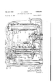
- Figure 1 is a vertical longitudinal section taken
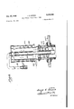
- Figure 5 is a vertical section similar to Figure '1, but showing a modified 'form 'of the water flow control means within the tank and which is connected to the outlet thereof.
- Figure 6 is a vertical section showing the suction jet and silencing means applied directly to the outlet leading from the tank to the bowl.
- I0 designates a ush tank preferably formed in a single piece from porcelain, plastics or the like and connected to the bottom thereof is a water Supply pipe II and a discharge pipe l2 which leads to the bowl or urinal.
- an upright pipe i 3 carrying on its upper end a valve housing I4 having a main chamber I5 normally closed by a cap I6 screwed into the top of housing I4, and a short duct I'I connecting the upper end of pipe II With said chamber.
- a centrally disposed tubular member i8 Formed integral with the bottom and side of housing I4 is a centrally disposed tubular member i8 provided in its upper end with a seat I9 for a diaphragm valve 20, preferably of rubber, which is clamped to vhousing I4 by the lower end of the cap I6.
- a tubular member 2I Passing through and clamped to the center of diaphragm 20, is a tubular member 2I which depends from a shallow metal cup 22 seated on top of said diaphragm; and seated in said cup 22 is a disc 23 of rubber having a central aperture 24.
- a vertical stem 25 Passing through the tube 2
- an eyelet 21 Seated in diaphragm 20 is an eyelet 21 which provides a bleed opening from the chamber I5; and loosely seated in said eyelet is a short piece of wire 28 having itsends 29 bent at right angles so as to retain it in said aperture.
- This member 28 moves lengthwise through eyelet 2'I in response to varying water pressures, thereby acting as a cleaner to prevent the aperture through the eyelet from becoming clogged with sediment or the like.
- Stem 25 extends downwardly through tubular member I8 and carries in position spaced above its lower end a disc 30 smaller in diameter than the internal diameter of the tube. Carried by the lower end .of the stem 25 is a 'block 3l that is guided for vertical movement in the lower portion of tube I8.
- notches 36 and 31 Formed in the top of arm 33 adjacent pivot 34 are notches 36 and 31, the latter being disposed outwardly from and being somewhat less in depth than notch 36.
- a short arm 42 carrying a weight 43 projects horizontally from the shaft 49 within the tank Ill, whereas a handle 44 is rigid with the shaft 45 outside the tank so as to 'be accessible Pto an operator.
- the handle 44 also extends horizontally, but in the direction opposite that in which the arm 42 extends so that downward motion of the handle 44 is ⁇ at all times 'resisted bythe -weight .43, the purpose being to .cause the weight 43 to ⁇ .return the handle 4.4 andthe other associated parts to their original position after the water in the-tank I has been evacuated, as will be described in greater detail hereinbelow.
- a sleeve 49 encircles the tube 45, .the inside diameter of the sleeve 49 being slightly greater than the overall radiusof the tube and its external spiral rib 41.
- the upper end of the sleeve 49 is closed by a top plate 4S, preferably integral therewith, which rests upon the upper end of The lower end of Vthe sleeve 49 is spaced a short distance above the bottom of the tank I0.
- the inner face of the wall of sleeve 49 is spaced a slight distance away from the outer edge of external rib 41.
- Tube 50 is spaced apart from the inner edge of internal iiange 46.
- a short spiral deflector 52 Seated in the upper end of outlet tube i2 is a short spiral deflector 52 very similar to the deilectors shown in my abovementioned Patent #2,372,848.
- a tube 53 is connected to the upper end of sleeve 49 where it extends through the sleeve to communicate with the interior thereof.
- This tube 53 extends downward to a point adjacent the lower end of said sleeve; and screw seated on the lower end of this tube, is a short tubel 54.v
- This tube- 54 is adjustable inasmuch as it can b e threaded to any selected position upon its supporting tube 53;, thereby varying Y the elevation which the water in the tank must reach while. the tank is flushing before air will bev rawn into the system throughl the; tube 53 to break the syphonic flushing action.
- a tube extends upward between the tube 45 and the sleeve 49, through one of the apertures and thence to a point adjacent aperture 56 in tube 59, the parts being so arranged that a jet issuing from thetube 69 will be directed through the aperture 55 .into the interior of 'the tube 50.
- a piston 6I Arranged for reciprocatory movement within the cylinder 59 is a piston 6I provided in its lower portion with a diametrically disposed port 62 adapted to establish communication between the lower ends of tubes 58 and 60 when the piston is in its uppermost position (see Figure 2).
- a rod 54 has its lower 'end pivotally connected to the piston 6I .and its upper Aehd't'o a 'short crank arm 65 vthat projects radially from shaft substantially in parallism with the 'arm 42 vwhich carries the weight 43 (seeFigur-e r3).
- a short portion 66 of an open ended rell tube 51 extends through the upper 'portionof tube 58 and the vertical leg of elbow 51, the upper 'end of said portion 36 terminating just above said elbow (see Figure 4) and from the lower Vportion of said tube 58, said reiill tube extends to and through a plug 63 seated in the upper end of tube 50.
- air inlet apertures 69 Formed through the wall of tube 58 within the enlarged lower end of elbow 51, are air inlet apertures 69, which are for the purpose of admitting air to tube 58 and thus break siphonic conditions which might develop and tendv to draw contaminated water fromthe bowl or urina] intov the tank.
- Diaphragm 20 is also forced onto its seat i9 by pressure of water from supply pipe I3 which enters chamber I5 through the tubular rivet 21. Under such conditions, finger 4I bears in recess 35. and arm 55 and rod 64 hold piston 6i at the lower end of its travel with port 62 out of registry with the tubes 58 and 6D.
- shaft 49 is rocked by downward pressure on handle 44, thereby swinging finger 4I so that it passes into shallow notch 31, thus swinging arm 33 on itsv axis 34 and forcing iioat 35'downward into the' water in the tank.
- the inner end of arm 33 elevates block 3I so l that head 26 oi stem 25 is lifted from aperture 24, thus permitting water under pressure within the chamber I5 toA pass through aperture 24 and tube 2i, thus permitting diaphragm 25 to iex upwardly under the influence of. waterflowing from supply pipes.
- This whirling motion of the water flowing through the discharge pipe I2 causes it to have such velocity that it develops a relatively high vacuum within the upper end of the tube 45; and since the upper end of the tube 45 communicates through the apertures 55 with the interior of the sleeve 49, the lower end of which opens directly into the tank I0, a syphonic action is started whereby water within the tank I is drawn upwards through the sleeve 49, thence through the apertures 55 and downwardly through the tube 45 to the discharge pipe I2.
- the whirling motion of the Water flowing through the tube 45 and discharge pipe I2 is maintained by both the external ribs 41 and the internal ribs 46. In this manner the water is caused to ilow from the tank I to the toilet fixture in a smooth silent flow which practically eliminates the gurgling and hissing noises which constitute one of the objectionable features of toilet flush tanks of more conventional design.
- Adjustable tube 54 on the lower end of tube 53 provides means for breaking the siphonic action at selected elevation in relation to the bottom of the tank.
- the modified constructions illustrated in Figs. 5 and 6 are especially designed as replacements for iiush tanks originally equipped with standard Douglas ttings including a tubular member seated in the bottom of tank Illa and connected to the tube leading to the bowl or urinal, the upper end of which member is provided with a seat for conventional hollow rubber valve and said member 1U also being provided with a lateral tubular extension 1I to which is secured the lower end of a conventional overow pipe 12.
- a tube 13 leads from the tank supply pipe 14 to a valve housing 15 having an inlet port 16 normally closed by a oat-controlled valve 11 and with a lower outlet port 18 and an upper outlet port 19.
- Valve 11 is reciprocally disposed within a horizontal cylinder 15a formed in the valve housing 15.
- An arm 30 carrying a oat 80a is pivoted at 8l to a bracket on the valve housing 15, with a pin 82 between the end of said arm and valve 11.
- a finger 83 projects upwardly from the end of arm above pivot 8l, said finger having a deep notch 83a and a shallow notch 83h for the reception of a finger 84 carried by a rock shaft 85 provided on its outer end with a handle 35a.
- the parts just described are practically the same in structure as the oat arm 33, notches 36 and 31, rock shaft 49, finger 4I, and handle 44 herein previously described.
- tube 86 Extending through the vertical portion of member 18, is a tube 86 having an outlet 86a communicating with the duct through extension 1l.
- the upper end of tube 86 is connected to one end of a laterally arranged tubular gooseneck 81, the otherend of which extends downward and rests on the bottom of the tank, thus providing a trap 81a.
- a tube 88 Depending from the upperportion of gooseneck 81 and disposed axially in tube 85 is a tube 88 provided in its upper portion with an air inlet aperture 88a. Surrounding the lower portion of this tube B8 is a slightly larger tube 89 provided with an externally arranged spiral flange 89a, which imparts whirling motion to the water as it leaves the tank through the tube 86.
- a vertical tube 90 which provides a support for a larger vertical tube 9
- carries a spirally disposed flange Sla.
- a shell 92 open at its lower end and closed at the top by a plate 92a, from which both the tube 9
- and the shell 92 are in communication with each other at their upper ends through apertures 8 Ib in the tube 9
- a depending tube 93 Secured to plate 92a is a depending tube 93, the upper end of which communicates with the upper end of the shell 92 and on the lower end of which is screw seated a short tube 93a, thus providing an adjustable Siphon breaker that is similar in both construction and functions to the previously described parts 53 and 54.
- a tube 94 Leading from valve housing 15 just below outlet port 18, is a tube 94 which extends downward, thence into the lower end of shell 92, thence upwardly between said shell and tube 9
- Formed in the lower portion ofthe wall oftube 95 is an air inlet aperturea whichadmitsair to the space between'tubes' T2 and' 95' and Within saicttube 12 to b real;siplior1ic ⁇ conditions therein, when the waterlevell in the tank passes below said inletaperture.
- valve 'i1 When valve 'i1 is opened -byy actuation of handle 85d waterwill flowfrlom pipe 1 3 through port i6 into the valve cham ber, tlie ⁇ nce out through port '18,. through tubes land 90, int'etrap. a., thus setting up' a s uction thrug'h the go'oseneck 81, tube 8E and outletfrQm the tank.
- Ashthe water passes throughtube Spiral flange 89a imparts whirling'motiontothe water so as to accelerate its flow and as aresult, storage water. from thetankwill bequickly drawn upward between tube 91' andshell v92,; thence vdownwardly between' tubes Stand, SZUto and through the gooseneck 81,.thus accorriplishing .the ushing function; ⁇ At, tlue s arne time .some of the Water from the tank will, by suction be drawn upward between tubeslz andev, thence ⁇ downward through Said tube 12 tonunite withthe water 4 discharging throughtube 8 6'.
- a toilet tank ushing apparatus the combination with atank having a water pressure supply pipe and an outlet, oa float-actuated valve for controlling the flow of water from said valve into said tank, an upright tubular member within said tank with its lower end ⁇ in communication with the outletfrom the tank, spirally disposed ribs on the inner and outer faces ofthe wall of said tubular member, means for inducing s'iphonic action comprisinga ductfor conveying water from said valveto the. interior of Said tubular member, a shell associated :with said tubular member, and means closing the upper ends of said shell and said tubularmember, saidshell and said tubular member being ,in communication with each other adjacent.
- Siphon .means comprising a Siphon outlet tube cmmunicatingat its lower end with Said tanks outlet and tubular Siphon inlet means communicating at its upper end with. the upper end of said Siphon outlet tube and at its lower end with the lower portion'of the interior of said tank, a duct leading from said valve into .position to dise charge water.
- a tank having a Water pressure supply pipe and an outlet, an inlet valve associated, with said supply pipe to control flow therefrom vrto said tank, a oat within said tank and operably connected to said valve to open said valve when said float is lowered
- vsiphon means comprising a Siphon outlet tube communicating at its lower end with said tanks outlet and tubular Siphon inlet means communicating at its upper end with the upper end of said siphonoutlet tube and at its lower end with the lower portion of theinterior of said tank, a duct leading from said valve into position to discharge Water therefrom into said Siphon outlet tube, means for Submerging said oat to lowered, valve-openingposition and therebyestablishing owithrough said duct to said Siphon outlettube toinduce discharge of water stored within said tank through Said Siphon means, means for retaining said submerged float in said lowered position until no longer supported therein by water stored within said tank and for thereafter releasing said float to permit return of said oat
- a .tank having a water pressure supply pipe and an outlet, an inlet f-valve associated with -said supply pipe to control owtherefrom to said tank, a float within Said tank and .operably connected to said valve to open said valve when said float iS lowered, an upstanding tubular member within said tank with. its lower yendin communication with said tanks outlet, a Shell surrounding and spaced from saidtubular member, means closing the upper end of .said shell, the upper end of said tubular member being-in communication with the upper end of said shell and Said shellopening atitslower end to the interior of Said tank and thereby being adapted .to.
- a tank having a water pressure supply pipe and an outlet, an inlet valve associated with said supply pipe to control fiow therefrom to said tank, a float within said tank and operably connected to said valve to open said valve when said float is lowered, an upstanding tubular member within said tank with its lower end in cornmunication with said tanks outlet, a shell surrounding and spaced from said tubular member, means closing the upper end of said shell, the upper end of said tubular member being in communication with the upper end of said shell and said shell opening at its lower end to the interior of said tank and thereby being adapted to conduct water stored within said tank upwardly to the top of said tubular member, spirally disposed ribs on the inner and outer faces of said tubular member, a duct leading from said valve in position to discharge water therefrom into said tubular member and thereby induce siphonic action to discharge water stored within said tank through said shell and said tubular member when said valve is opened, means for submerging said float to lowered, valve-opening position,
- siphon means comprising a siphon outlet tube communicating at its lower end with said tanks outlet and tubular siphon inlet means communicating at its upper end with the upper end of said siphon outlet tube and at its lower end with the lower portion of the interior of said tank, a duct leading from said valve into position to discharge water therefrom into said siphon outlet tube, a shaft mounted for rocking movement within said tank, means accessible outside said tank for rocking said shaft, a finger rigid with said shaft, said arm having notches therein of different radial distances from the axis of said shaft and adapted selectively to receive said finger, said finger being adapted to lower said float into submerged, valve-opening position when moved into that one of said notches at the lesser radial distance from the
- siphon means comprising a siphon outlet tube comrnunicatingV at its lower end with said tanks outlet and tubular siphon inlet means communicating at its upper end with the upper end of said siphon outlet tube and at its lower end with the lower portion of the interior of said tank, a duct leading from said valve into position to discharge water therefrom into said siphon outlet tube, a shaft mounted for rocking movement within said tank, means accessible outside said tank for rocking said shaft, a finger rigid with said shaft, said arm having notches therein of different radial distances from the axis of said shaft and adapted selectively to receive said finger, said finger being adapted to lower said float into submerged, valve-opening position when moved into that one of said notches at the lesser
Landscapes
- Health & Medical Sciences (AREA)
- Life Sciences & Earth Sciences (AREA)
- Engineering & Computer Science (AREA)
- Hydrology & Water Resources (AREA)
- Public Health (AREA)
- Water Supply & Treatment (AREA)
- Sanitary Device For Flush Toilet (AREA)
Description
3 Sheds-Sheet .,2. 3. OWENS ANTISIPHONIC TOILET FLUSH TANK Q BY Filed Aug. 29, 1945 Dec. 27, J Q OWENS ANTISIPHONIG TOILET FLUSH TANK 3 Sheets-Sheet 2 Filed Aug. 29, 1945 INVENTOR. JESSE C. Owe/ys NJ E.
z f r i L TTo/eNEy Dec. 27, 1949 1. c. owENs 2,492,436
ANTISIPHONIC TOILET FLUSH TANK Filed Aug. 29, 1945 s sheets-sheet :s
' INVENTOR. 1f555 C. 0 wE/vs Arron/Ey.
Patented Dec. 27, 1949 vUNITED STATES PATENT GFFICE ANTISIPHONIC TOILET FLUSH TANK Jesse C. Owens, Los Angeles, Calif.
Application August 29, 1945, Serial No. 613,310
7 Claims. (Cl. 4-44) My invention relates to an anti-siphonic toilet ilushing tank of the general type disclosed in my co-pending applications for U. S. Letters Patent tiled February 15, 1943, Serial No. 475,863, issued as Patent No. 2,412,691, December 17, 1946, and Serial No. 570,147, iiled December 28, 1944, also U. S. Letters Patent No. 2,372,848, issued to me Algril 3, 1945, on Toilet tank outlet tting and e ow.
The principal objects of my invention are, to-
generally improve upon and simplify the construction of the tanks and ilushing means disclosed in my aforesaid co-pending applications,
.to provide simple and eiective means for positively counteracting and eliminating the possi-- bility of the development of siphonic action in the tank, its valve and connections, tending to draw contaminated water into the tank and the fresh water supply pipe connected thereto; further to provide a valve and tank which are prac-"- tically noiseless in operation, which desirable feature results from the employment of simple and emcient means for eliminating the gurgling and hissing noises ordinarily produced by the water passing into and from the tank, and further, to=ry provide means for establishing and maintaining a rapid flow of ilushing water into, through and from the tank and thereby materially shortening the period of the flushing and refilling functions. v Further objects of my invention are, to provide tank flushing means which may be built into the tank as an integral part thereof, or used as a replacement for the flushing means installed in tanks already in service, to provid-e adjustable means for controlling the action of the anti#iv siphonic means, and further, to provide iiushing connections which may be located in different positions within the tank.
With the foregoing and other objects in view, my invention consists in certain features of con struction and arrangement of parts which will be hereinafter more fully described and claimed and illustrated in the accompanying drawing, in which:
Figure 1 is a vertical longitudinal section taken Figure 5 is a vertical section similar to Figure '1, but showing a modified 'form 'of the water flow control means within the tank and which is connected to the outlet thereof.
Figure 6 is a vertical section showing the suction jet and silencing means applied directly to the outlet leading from the tank to the bowl.
Referring by numerals to the accompanying drawings, particularly to Figures 1, 2 and 3, I0 designates a ush tank preferably formed in a single piece from porcelain, plastics or the like and connected to the bottom thereof is a water Supply pipe II and a discharge pipe l2 which leads to the bowl or urinal.
Connected to the supply pipe II is an upright pipe i 3, carrying on its upper end a valve housing I4 having a main chamber I5 normally closed by a cap I6 screwed into the top of housing I4, and a short duct I'I connecting the upper end of pipe II With said chamber.
Formed integral with the bottom and side of housing I4 is a centrally disposed tubular member i8 provided in its upper end with a seat I9 for a diaphragm valve 20, preferably of rubber, which is clamped to vhousing I4 by the lower end of the cap I6.
Passing through and clamped to the center of diaphragm 20, is a tubular member 2I which depends from a shallow metal cup 22 seated on top of said diaphragm; and seated in said cup 22 is a disc 23 of rubber having a central aperture 24.
Passing through the tube 2| and aperture 24 is a vertical stem 25, smaller in diameter than said aperture; and on the upper end of said stem is a head 26 which normally closes aperture 24.
Seated in diaphragm 20 is an eyelet 21 which provides a bleed opening from the chamber I5; and loosely seated in said eyelet is a short piece of wire 28 having itsends 29 bent at right angles so as to retain it in said aperture. This member 28 moves lengthwise through eyelet 2'I in response to varying water pressures, thereby acting as a cleaner to prevent the aperture through the eyelet from becoming clogged with sediment or the like.
Stem 25 extends downwardly through tubular member I8 and carries in position spaced above its lower end a disc 30 smaller in diameter than the internal diameter of the tube. Carried by the lower end .of the stem 25 is a 'block 3l that is guided for vertical movement in the lower portion of tube I8.
Loosely arranged in a recess 32in block 3|, is the end-of an arm 33 which is pivoted at 34 on the the tubo .45-
3 outside of the housing i4; and the outer end of the arm carries a float 35.
Formed in the top of arm 33 adjacent pivot 34 are notches 36 and 31, the latter being disposed outwardly from and being somewhat less in depth than notch 36.
Disposed above and at right angles to arm 33 and journalled in a bracket 38 on housing I4 and a bearingl39 in the side wall of tank l0, is a shaft 45 from which depends a ngerAI, the lower end of which normally rests in the deep notch 35 and which when the tank is flushed, moves into shallow notch 31.
A short arm 42 carrying a weight 43 projects horizontally from the shaft 49 within the tank Ill, whereas a handle 44 is rigid with the shaft 45 outside the tank so as to 'be accessible Pto an operator. The handle 44 also extends horizontally, but in the direction opposite that in which the arm 42 extends so that downward motion of the handle 44 is `at all times 'resisted bythe -weight .43, the purpose being to .cause the weight 43 to `.return the handle 4.4 andthe other associated parts to their original position after the water in the-tank I has been evacuated, as will be described in greater detail hereinbelow.
Formed integral withand projecting upwardly from the bottom of tank I Il around the outlet opening to whichdischarge .I2 is connected, is an upstanding tube 45 provided with an internal spiral rib 4 6 and a similar external spiral rib 41.
A sleeve 49 encircles the tube 45, .the inside diameter of the sleeve 49 being slightly greater than the overall radiusof the tube and its external spiral rib 41. The upper end of the sleeve 49 is closed by a top plate 4S, preferably integral therewith, which rests upon the upper end of The lower end of Vthe sleeve 49 is spaced a short distance above the bottom of the tank I0.
The inner face of the wall of sleeve 49 is spaced a slight distance away from the outer edge of external rib 41.
Seated in the center of plate 48 is the upper end of a depending tube 59, the lower end of which terminates just above the upper end of outlet pipe l2; and formed in the lower portion of the wallef said tube 59, are apertures I. Tube 50 is spaced apart from the inner edge of internal iiange 46. Seated in the upper end of outlet tube i2 is a short spiral deflector 52 very similar to the deilectors shown in my abovementioned Patent #2,372,848.
The upper end of a tube 53 is connected to the upper end of sleeve 49 where it extends through the sleeve to communicate with the interior thereof. This tube 53 extends downward to a point adjacent the lower end of said sleeve; and screw seated on the lower end of this tube, is a short tubel 54.v This tube- 54is adjustable inasmuch as it can b e threaded to any selected position upon its supporting tube 53;, thereby varying Y the elevation which the water in the tank must reach while. the tank is flushing before air will bev rawn into the system throughl the; tube 53 to break the syphonic flushing action.
Formed. through the, wall o f the tube.V 45 just below-itsupper end are fairly large apertures 55 and formed throughthe wall, of tube-50just below, plateV 48 is a similar aperture156.
Seated inv theV side of. housing I 4 and communieating with the bore of the tubular member I8 is the open upper end of an elbow 51' (seefFigure 4) in, thedepending end oft .whichr isk seated the end of a, tube whichextends downwarditoa pointl near the bottom of tank I0 and there leads horizontally into a short vertically disposed cylinder 59.
From the opposite side of cylinder 59, a tube extends upward between the tube 45 and the sleeve 49, through one of the apertures and thence to a point adjacent aperture 56 in tube 59, the parts being so arranged that a jet issuing from thetube 69 will be directed through the aperture 55 .into the interior of 'the tube 50.
Arranged for reciprocatory movement within the cylinder 59 is a piston 6I provided in its lower portion with a diametrically disposed port 62 adapted to establish communication between the lower ends of tubes 58 and 60 when the piston is in its uppermost position (see Figure 2).
Formed through the upper portion of piston 6I is an inclined port 63 which when the piston is in its lowermost position establishes communication between the lower end of tube 58 and the interior of tank I9 (see Figure 1).
A rod 54 has its lower 'end pivotally connected to the piston 6I .and its upper Aehd't'o a 'short crank arm 65 vthat projects radially from shaft substantially in parallism with the 'arm 42 vwhich carries the weight 43 (seeFigur-e r3). s
A short portion 66 of an open ended rell tube 51 extends through the upper 'portionof tube 58 and the vertical leg of elbow 51, the upper 'end of said portion 36 terminating just above said elbow (see Figure 4) and from the lower Vportion of said tube 58, said reiill tube extends to and through a plug 63 seated in the upper end of tube 50.
Formed through the wall of tube 58 within the enlarged lower end of elbow 51, are air inlet apertures 69, which are for the purpose of admitting air to tube 58 and thus break siphonic conditions which might develop and tendv to draw contaminated water fromthe bowl or urina] intov the tank.
Under normal conditions 'or while inactive, the operating parts of the flushing apparatus are positioned as illustrated in Figure l, with oat 35 on top of the water within tank I9 and acting through arm 33, block 3| and stem 25 to hold diaphragm 25 on its seat I9 thus cutting off how of water through the valve.
To effect the flushing function shaft 49 is rocked by downward pressure on handle 44, thereby swinging finger 4I so that it passes into shallow notch 31, thus swinging arm 33 on itsv axis 34 and forcing iioat 35'downward into the' water in the tank.
The inner end of arm 33 elevates block 3I so l that head 26 oi stem 25 is lifted from aperture 24, thus permitting water under pressure within the chamber I5 toA pass through aperture 24 and tube 2i, thus permitting diaphragm 25 to iex upwardly under the influence of. waterflowing from supply pipes. I-Ii and I3.,` through. duct l1 beneath the diaphragm. andi then downwardly into the. tubular mem-ber I.8,. from which the greater portion Will flow through the elbow 51 into the tube 58.
As shaft 49 is rocked, arm 65 is swung upward, thereby elevating rod 54 and piston 5I; so that port 52 is brought into registration withv the ends ofv tubesY 58 andv 59 connected-V tov cylinderl .5'9" and thus the water carriedufroni' theV tube IB'UY thetube 58 will be delivered to the tube BIJ, which will direct it through the aperture 55 in the tube 50 whence it will flow through apertures 5I into the lower portion of tube 45.
Thus it may be seen that when the handle 44 is depressed, the water under full service pressure is ejected almost instantly from the outlet end of the tube 69 into the central tube 59, the immediacy of this action being the result of connecting the tube B'directly to the source of water under full pressure. This arrangement also causes water to be delivered into the tube 50 at such velocity that it issues from the orices 5I in the lower end of the tube 50 also at considerable velocity. The rib 46 imparts a spiral motion to the water thus delivered at considerable velocity within the lower end of the tube 45 and this whirling motion is augmented by the spiral de-` flector 52. This whirling motion of the water flowing through the discharge pipe I2 causes it to have such velocity that it develops a relatively high vacuum within the upper end of the tube 45; and since the upper end of the tube 45 communicates through the apertures 55 with the interior of the sleeve 49, the lower end of which opens directly into the tank I0, a syphonic action is started whereby water within the tank I is drawn upwards through the sleeve 49, thence through the apertures 55 and downwardly through the tube 45 to the discharge pipe I2. The whirling motion of the Water flowing through the tube 45 and discharge pipe I2 is maintained by both the external ribs 41 and the internal ribs 46. In this manner the water is caused to ilow from the tank I to the toilet fixture in a smooth silent flow which practically eliminates the gurgling and hissing noises which constitute one of the objectionable features of toilet flush tanks of more conventional design.
When the water level within the tank lowers to such a point as to permit iioat 35 to rest in normal position on the surface of the water and lower a short distance therewith, notch 31 will move downward soY as to release nger 4I and under the influence of weight 43 shaft 48 will rock -back to its normal position so that arm 65 and rod 54 will move piston 5I downward. This will disconnect the tube 69 frornthe tube 58 by moving the port 52 out of registry therewith and will bring the lower end of the inclined port S3 into registry with the end of the tube 58 so that thereafter water owing through the tube 58 will pass directly into the tank I0, causing the tank to be reiilled.
As the water rises within the tank, the oat 35 will return to its normal position and arm 33, swinging on its pivot 34 will finally move block 3l and stem 25 downward until head 2B closes aperture 24 and subsequently the pressure of water bleeding unto chamber I5 through tubular rivet 21 will act on top of diaphragm 20 and force same downward to cut 01T further flow of water into tube I8.
Adjustable tube 54 on the lower end of tube 53 provides means for breaking the siphonic action at selected elevation in relation to the bottom of the tank.
The modified constructions illustrated in Figs. 5 and 6 are especially designed as replacements for iiush tanks originally equipped with standard Douglas ttings including a tubular member seated in the bottom of tank Illa and connected to the tube leading to the bowl or urinal, the upper end of which member is provided with a seat for conventional hollow rubber valve and said member 1U also being provided with a lateral tubular extension 1I to which is secured the lower end of a conventional overow pipe 12.
In accordance with my invention, a tube 13 leads from the tank supply pipe 14 to a valve housing 15 having an inlet port 16 normally closed by a oat-controlled valve 11 and with a lower outlet port 18 and an upper outlet port 19. Valve 11 is reciprocally disposed within a horizontal cylinder 15a formed in the valve housing 15.
An arm 30 carrying a oat 80a is pivoted at 8l to a bracket on the valve housing 15, with a pin 82 between the end of said arm and valve 11. A finger 83 projects upwardly from the end of arm above pivot 8l, said finger having a deep notch 83a and a shallow notch 83h for the reception of a finger 84 carried by a rock shaft 85 provided on its outer end with a handle 35a. The parts just described are practically the same in structure as the oat arm 33, notches 36 and 31, rock shaft 49, finger 4I, and handle 44 herein previously described.
Extending through the vertical portion of member 18, is a tube 86 having an outlet 86a communicating with the duct through extension 1l. The upper end of tube 86 is connected to one end of a laterally arranged tubular gooseneck 81, the otherend of which extends downward and rests on the bottom of the tank, thus providing a trap 81a.
Depending from the upperportion of gooseneck 81 and disposed axially in tube 85 is a tube 88 provided in its upper portion with an air inlet aperture 88a. Surrounding the lower portion of this tube B8 is a slightly larger tube 89 provided with an externally arranged spiral flange 89a, which imparts whirling motion to the water as it leaves the tank through the tube 86.
-Seated in the bottom of that portion of the gooseneck having the trap 81a, is the lower end of a vertical tube 90 which provides a support for a larger vertical tube 9|, the lower end of the latter communicating with the opening into r trap 81a. The outer face of the tube 9| carries a spirally disposed flange Sla.
Surrounding tube 9| and its spiral flange is a shell 92 open at its lower end and closed at the top by a plate 92a, from which both the tube 9| and the shell 92 depend. The tube 9| and the shell 92 are in communication with each other at their upper ends through apertures 8 Ib in the tube 9|.
A tube B2b rigid with and surrounding the upper portion of the tube 90, supports the plate 92a, and the lower portion of said tube 9i) is provided with outlet apertures 9Ila below the lower end of the tube 92h and communicating with the lower end of the tube 9|. Secured to plate 92a is a depending tube 93, the upper end of which communicates with the upper end of the shell 92 and on the lower end of which is screw seated a short tube 93a, thus providing an adjustable Siphon breaker that is similar in both construction and functions to the previously described parts 53 and 54.
Leading from valve housing 15 just below outlet port 18, is a tube 94 which extends downward, thence into the lower end of shell 92, thence upwardly between said shell and tube 9|, thence through one of the apertures Sib to enable the discharge end of said tube 94 to extend into the upper end of tube 9B.
Surrounding overflow tube 12 is a larger tube 95 open at its lower end and closed at its upper 9 5. provided on its inner. ange 95o; secured to' the c enter of cali? 3517;. S' the rupper endI of a Small tube 95d open at both ends;amdl whih' extends through tube l2 and terminates'within ithe lateral extension ll of the outlet' tube l!!v in the bottom 0f thetank Illa, s ,y Formed in the lower portion ofthe wall oftube 95 is an air inlet aperturea whichadmitsair to the space between'tubes' T2 and' 95' and Within saicttube 12 to b real;siplior1ic` conditions therein, when the waterlevell in the tank passes below said inletaperture..
When valve 'i1 is opened -byy actuation of handle 85d waterwill flowfrlom pipe 1 3 through port i6 into the valve cham ber, tlie` nce out through port '18,. through tubes land 90, int'etrap. a., thus setting up' a s uction thrug'h the go'oseneck 81, tube 8E and outletfrQm the tank.
V., Ashthe water passes throughtube Spiral flange 89a imparts whirling'motiontothe water so as to accelerate its flow and as aresult, storage water. from thetankwill bequickly drawn upward between tube 91' andshell v92,; thence vdownwardly between' tubes Stand, SZUto and through the gooseneck 81,.thus accorriplishing .the ushing function; `At, tlue s arne time .some of the Water from the tank will, by suction be drawn upward between tubeslz andev, thence `downward through Said tube 12 tonunite withthe water 4 discharging throughtube 8 6'.
Before Yvalve 1l closeS acertam amount o f water will pass through refill tube 51B to renll the b0W1 0I`..U-.I`n91,
In some instances it Inay be found desirable to eliminate the gooseneck 8 1 and as illustrated in Fig 6 t9 InQunt. t he lcrvrerv end oijwtube ai ,in the upper end o f tube lll andgsa'idwtube Si l carry? ing the associated.; rarltseand; iaieuide tube 88, tube 9|, shell'92', tubes 93and 93a; also water pressure Supplyppell vThe function. of this -structure isA the same asy that of the correspondinglstructure illustrated in Fie. 5 and. hereaitedssirbeli The use of a gooseneck enables 'tubewl and parts associated therew liltebe locatedN at any convenient pointori 'thefbottom of the tank within a. radius o f approximately 27'() degrees from the outletjiltting 10,;
It will be changes in ,I'
the Size, form and censtructifonof ,thevarious parts of my improved flush tank may be made and substitutedfor those herein Shown and described, without departing fromthe spirit of the invention, the scope of which is Set forth in the appended claims.
Iclaim:
1. In a toilet tank ushing apparatus, the combination with atank having a water pressure supply pipe and an outlet, oa float-actuated valve for controlling the flow of water from said valve into said tank, an upright tubular member within said tank with its lower end` in communication with the outletfrom the tank, spirally disposed ribs on the inner and outer faces ofthe wall of said tubular member, means for inducing s'iphonic action comprisinga ductfor conveying water from said valveto the. interior of Said tubular member, a shell associated :with said tubular member, and means closing the upper ends of said shell and said tubularmember, saidshell and said tubular member being ,in communication with each other adjacent. theinnpperends,` and au sharpening at .is .1ere ,end n nhl@ interior of said tank and thereby being adapted to ccnl duct water stored Withinhs. tank upwardly to the. top of Said tubularv member. f
2. In a ushingv app'aratue,.th`e combination of a tank having awatr pressure supplypipe and an outlet, .an inlet. vvalve associated with Said supply pipe to control now therefrom to said tank, a float within said tank andoperably connected to said valve to4 open` said valve when said float is lowered, Siphon .means comprising a Siphon outlet tube cmmunicatingat its lower end with Said tanks outlet and tubular Siphon inlet means communicating at its upper end with. the upper end of said Siphon outlet tube and at its lower end with the lower portion'of the interior of said tank, a duct leading from said valve into .position to dise charge water. therefroml into said .Siphon outlet tube, means for submerging saidfloat to lowered, valve-opening .position and thereby establishing now through Said duct to Said siphon outlet tube to induce discharge of water lstcred within said tank throughlsaiclsiphon means, and means operable subsequently tovinducing said discharge of stored water for diverting water flowing through said duct from said Siphon means and discharging it into said tank.
3. In a flushing apparatus, the combination of a tank having a Water pressure supply pipe and an outlet, an inlet valve associated, with said supply pipe to control flow therefrom vrto said tank, a oat within said tank and operably connected to said valve to open said valve when said float is lowered, vsiphon means comprising a Siphon outlet tube communicating at its lower end with said tanks outlet and tubular Siphon inlet means communicating at its upper end with the upper end of said siphonoutlet tube and at its lower end with the lower portion of theinterior of said tank, a duct leading from said valve into position to discharge Water therefrom into said Siphon outlet tube, means for Submerging said oat to lowered, valve-openingposition and therebyestablishing owithrough said duct to said Siphon outlettube toinduce discharge of water stored within said tank through Said Siphon means, means for retaining said submerged float in said lowered position until no longer supported therein by water stored within said tank and for thereafter releasing said float to permit return of said oat to valve-closing position as said tank is nlled, and means operable -Subsequently to inducing said discharge of Stored watervfor diverting water flowing throughsaid duct from said Siphon means and discharging it into said tank.
4. In flushing apparatus, the combination of a .tank having a water pressure supply pipe and an outlet, an inlet f-valve associated with -said supply pipe to control owtherefrom to said tank, a float within Said tank and .operably connected to said valve to open said valve when said float iS lowered, an upstanding tubular member within said tank with. its lower yendin communication with said tanks outlet, a Shell surrounding and spaced from saidtubular member, means closing the upper end of .said shell, the upper end of said tubular member being-in communication with the upper end of said shell and Said shellopening atitslower end to the interior of Said tank and thereby being adapted .to. conduct water stored within said tank upwardly to thetop of said tubular member, a duct leading from Said valve in position'to discharge water therefrom into said tubular member and thereby induce s ipnonic' actionlto discharge water stored Within i ugh. said'fshell". arid said tubulai` member' when" Said valve is" opened,V` means furY 9 submerging said float to lowered, valve-opening position, and means operable while said float is in said lowered position for diverting water flowing through said duct from said tubular member and into said tank.
5. In flushing apparatus, the combination of a tank having a water pressure supply pipe and an outlet, an inlet valve associated with said supply pipe to control fiow therefrom to said tank, a float within said tank and operably connected to said valve to open said valve when said float is lowered, an upstanding tubular member within said tank with its lower end in cornmunication with said tanks outlet, a shell surrounding and spaced from said tubular member, means closing the upper end of said shell, the upper end of said tubular member being in communication with the upper end of said shell and said shell opening at its lower end to the interior of said tank and thereby being adapted to conduct water stored within said tank upwardly to the top of said tubular member, spirally disposed ribs on the inner and outer faces of said tubular member, a duct leading from said valve in position to discharge water therefrom into said tubular member and thereby induce siphonic action to discharge water stored within said tank through said shell and said tubular member when said valve is opened, means for submerging said float to lowered, valve-opening position, and means operable while said float is in said lowered position for diverting water flowing through said duct from 'said tubular member and into said tank.
6. In flushing apparatus, the combination of a tank having a water pressure supply pipe and an outlet, an inlet valve associated with said supply pipe to control ow therefrom to said tank, a float within said tank, an arm operably connecting said float to said valve to open said valve when said float is lowered, siphon means comprising a siphon outlet tube communicating at its lower end with said tanks outlet and tubular siphon inlet means communicating at its upper end with the upper end of said siphon outlet tube and at its lower end with the lower portion of the interior of said tank, a duct leading from said valve into position to discharge water therefrom into said siphon outlet tube, a shaft mounted for rocking movement within said tank, means accessible outside said tank for rocking said shaft, a finger rigid with said shaft, said arm having notches therein of different radial distances from the axis of said shaft and adapted selectively to receive said finger, said finger being adapted to lower said float into submerged, valve-opening position when moved into that one of said notches at the lesser radial distance from the axis of said shaft and to be retained within that notch until the water level within said tank is lowered suf- -ficiently for said float and arm to move downwards away from engagement with said finger, and means operable by gravity for removing said nnger from registry with said one of said notches when lreleased from said arm and into registry with the other of said notches whereby said float and arm are adapted to move to their uppermost, valve-closing position as said tank is filled.
7. In flushing apparatus, the combination of a tank having a water pressure supply pipe and an outlet, an inlet valve associated with said supply pipe to control flow therefrom to said tank, a float within said tank, an arm operably connecting said float to said valve to open said valve when said float is lowered, siphon means comprising a siphon outlet tube comrnunicatingV at its lower end with said tanks outlet and tubular siphon inlet means communicating at its upper end with the upper end of said siphon outlet tube and at its lower end with the lower portion of the interior of said tank, a duct leading from said valve into position to discharge water therefrom into said siphon outlet tube, a shaft mounted for rocking movement within said tank, means accessible outside said tank for rocking said shaft, a finger rigid with said shaft, said arm having notches therein of different radial distances from the axis of said shaft and adapted selectively to receive said finger, said finger being adapted to lower said float into submerged, valve-opening position when moved into that one of said notches at the lesser radial distance from the axis of said shaft and to be retained within that notch until the water level within said tank is lowered sufiiciently for said float and arm to move downwards away from engagement with said finger, means operable by gravity for removing said finger from registry with said one of said notches when released from said arm and into registry with the other of said notches whereby said float and arm are adapted to move to their uppermost, valve-closing position as said tank is filled, and means operable upon release of said finger by said arm for diverting water flowing through said duct from said tubular member and discharging it into said tank.
JESSE C. OWENS.
REFERENCES CITED The following references are of record in the file of this patent:
UNITED STATES PATENTS Number Name Date 460,485 McFarland Sept. 29, 1891 1,625,311 Gondolf Apr. 19, 1927 2,068,252 Weber Jan. 19, 1937 2,073,835 Finley et a1 Mar. 16, 1937 2,372,848 Owens Apr. 3, 1945 FOREIGN PATENTS .Number Country Date 14,699 Great Britain June 7, 1897 26,557 Australia May 7, 1930 123,879 Switzerland Jan.2, 1928 187,189 Germany June 19, 1907 460,847 Germany June 6, 1928 464,588 Great Britain Apr. 21, 1937 667,534 France Oct. 17, 1929
Priority Applications (1)
| Application Number | Priority Date | Filing Date | Title |
|---|---|---|---|
| US613310A US2492436A (en) | 1945-08-29 | 1945-08-29 | Antisiphonic toilet flush tank |
Applications Claiming Priority (1)
| Application Number | Priority Date | Filing Date | Title |
|---|---|---|---|
| US613310A US2492436A (en) | 1945-08-29 | 1945-08-29 | Antisiphonic toilet flush tank |
Publications (1)
| Publication Number | Publication Date |
|---|---|
| US2492436A true US2492436A (en) | 1949-12-27 |
Family
ID=24456771
Family Applications (1)
| Application Number | Title | Priority Date | Filing Date |
|---|---|---|---|
| US613310A Expired - Lifetime US2492436A (en) | 1945-08-29 | 1945-08-29 | Antisiphonic toilet flush tank |
Country Status (1)
| Country | Link |
|---|---|
| US (1) | US2492436A (en) |
Cited By (6)
| Publication number | Priority date | Publication date | Assignee | Title |
|---|---|---|---|---|
| US3400731A (en) * | 1966-05-09 | 1968-09-10 | Robert R. Mccornack | Fluid valve with self-cleaning metering orifice |
| US3994313A (en) * | 1975-02-20 | 1976-11-30 | Brandelli Anthony R | Toilet bowl valve |
| US4193145A (en) * | 1978-06-29 | 1980-03-18 | Garon Processing Co. | Toilet flushing valve mechanism |
| US4230145A (en) * | 1978-03-13 | 1980-10-28 | Badders Edwin T | Fluid control valve |
| US20170058503A1 (en) * | 2015-04-16 | 2017-03-02 | Komoo Intelligent Technology Co., Ltd. | Toilet pan and water replenishing device for flush rim thereof |
| US20220220716A1 (en) * | 2019-08-07 | 2022-07-14 | Eco (Xiamen) Technology Inc. | Water outlet box of pressure-type flushing system and toilet using the water outlet box |
Citations (12)
| Publication number | Priority date | Publication date | Assignee | Title |
|---|---|---|---|---|
| DE187189C (en) * | ||||
| US460485A (en) * | 1891-09-29 | mcfarland | ||
| GB189714699A (en) * | 1897-06-17 | 1898-04-16 | Richard Brown Evered | Improvements in Automatic Flushing Apparatus. |
| US1625311A (en) * | 1922-06-06 | 1927-04-19 | Gondolf Nicholas Joseph | Flushing tank |
| CH123879A (en) * | 1926-12-14 | 1928-01-02 | Jun Neyer Josef | Cistern for water closets. |
| DE460847C (en) * | 1928-06-06 | Handelmij R S Stokvis & Zonen | Waste rinsing device with an open water tank and a built-in elbow pipe lifter, which is operated by a low-strength water jet | |
| FR667534A (en) * | 1929-01-17 | 1929-10-17 | Cistern for water closets | |
| AU2655730A (en) * | 1930-05-07 | 1931-05-07 | Wallace Mcclellan Henry | Improvements in flushing cisterns |
| US2068252A (en) * | 1936-01-11 | 1937-01-19 | Walter C Weber | Packless ejector flush valve |
| US2073835A (en) * | 1935-11-11 | 1937-03-16 | Walter H Finley | Flush tank apparatus |
| GB464588A (en) * | 1935-11-27 | 1937-04-21 | Veerappanchatram Ganesh Iyer | Improvements in syphons |
| US2372848A (en) * | 1942-11-04 | 1945-04-03 | Jesse C Owens | Toilet tank outlet fitting and elbow |
Family Cites Families (1)
| Publication number | Priority date | Publication date | Assignee | Title |
|---|---|---|---|---|
| AU2655730B (en) * | 1930-05-07 | 1931-05-07 | Wallace Mcclellan Henry | Improvements in flushing cisterns |
-
1945
- 1945-08-29 US US613310A patent/US2492436A/en not_active Expired - Lifetime
Patent Citations (12)
| Publication number | Priority date | Publication date | Assignee | Title |
|---|---|---|---|---|
| DE187189C (en) * | ||||
| US460485A (en) * | 1891-09-29 | mcfarland | ||
| DE460847C (en) * | 1928-06-06 | Handelmij R S Stokvis & Zonen | Waste rinsing device with an open water tank and a built-in elbow pipe lifter, which is operated by a low-strength water jet | |
| GB189714699A (en) * | 1897-06-17 | 1898-04-16 | Richard Brown Evered | Improvements in Automatic Flushing Apparatus. |
| US1625311A (en) * | 1922-06-06 | 1927-04-19 | Gondolf Nicholas Joseph | Flushing tank |
| CH123879A (en) * | 1926-12-14 | 1928-01-02 | Jun Neyer Josef | Cistern for water closets. |
| FR667534A (en) * | 1929-01-17 | 1929-10-17 | Cistern for water closets | |
| AU2655730A (en) * | 1930-05-07 | 1931-05-07 | Wallace Mcclellan Henry | Improvements in flushing cisterns |
| US2073835A (en) * | 1935-11-11 | 1937-03-16 | Walter H Finley | Flush tank apparatus |
| GB464588A (en) * | 1935-11-27 | 1937-04-21 | Veerappanchatram Ganesh Iyer | Improvements in syphons |
| US2068252A (en) * | 1936-01-11 | 1937-01-19 | Walter C Weber | Packless ejector flush valve |
| US2372848A (en) * | 1942-11-04 | 1945-04-03 | Jesse C Owens | Toilet tank outlet fitting and elbow |
Cited By (8)
| Publication number | Priority date | Publication date | Assignee | Title |
|---|---|---|---|---|
| US3400731A (en) * | 1966-05-09 | 1968-09-10 | Robert R. Mccornack | Fluid valve with self-cleaning metering orifice |
| US3994313A (en) * | 1975-02-20 | 1976-11-30 | Brandelli Anthony R | Toilet bowl valve |
| US4230145A (en) * | 1978-03-13 | 1980-10-28 | Badders Edwin T | Fluid control valve |
| US4193145A (en) * | 1978-06-29 | 1980-03-18 | Garon Processing Co. | Toilet flushing valve mechanism |
| US20170058503A1 (en) * | 2015-04-16 | 2017-03-02 | Komoo Intelligent Technology Co., Ltd. | Toilet pan and water replenishing device for flush rim thereof |
| US9951506B2 (en) * | 2015-04-16 | 2018-04-24 | Komoo Intelligent Technology Co., Ltd. | Water replenishing device for a flush rim of a toilet and toilet including the same |
| US20220220716A1 (en) * | 2019-08-07 | 2022-07-14 | Eco (Xiamen) Technology Inc. | Water outlet box of pressure-type flushing system and toilet using the water outlet box |
| US11946240B2 (en) * | 2019-08-07 | 2024-04-02 | Eco (Xiamen) Technology Inc. | Water outlet box of pressure-type flushing system and toilet using the water outlet box |
Similar Documents
| Publication | Publication Date | Title |
|---|---|---|
| US3172128A (en) | Water supply system for water closet | |
| US2283973A (en) | Antisiphonic flush valve and silencer | |
| US2294785A (en) | Siphon breaker and valve | |
| US2492436A (en) | Antisiphonic toilet flush tank | |
| US2442927A (en) | Tank inlet valve means | |
| US2409890A (en) | Antisiphon ball cock valve | |
| CN109764465B (en) | Water tank and humidifier with dual water valves | |
| US2068252A (en) | Packless ejector flush valve | |
| US3211172A (en) | Closet tank fittings | |
| US2173070A (en) | Valve and water supply mechanism | |
| US1794640A (en) | Tank-flushing valve | |
| US2740129A (en) | Valve mechanism for flush tanks | |
| US1896950A (en) | Flush valve | |
| US2046792A (en) | Nonsiphoning float valve | |
| US3147762A (en) | Device for silencing water flowing into storage tank of water closet | |
| US2406507A (en) | Ventilating and deodorizing toilet | |
| US2083486A (en) | Flush valve | |
| US2229600A (en) | Antisiphon silent valve structure | |
| US2491130A (en) | Flushing tank and valve | |
| US2448231A (en) | Toilet flushing assembly | |
| US2941542A (en) | Anti-siphon ball cock valve | |
| US2199094A (en) | Cleansing and deodorizing device for water closets | |
| US2146794A (en) | Ball cock | |
| US3151338A (en) | Apparatus for flushing toilets | |
| US3084350A (en) | Toilet bowl disinfectant injector |