US2489936A - Seal assembly for gyratory crushers - Google Patents
Seal assembly for gyratory crushers Download PDFInfo
- Publication number
- US2489936A US2489936A US753466A US75346647A US2489936A US 2489936 A US2489936 A US 2489936A US 753466 A US753466 A US 753466A US 75346647 A US75346647 A US 75346647A US 2489936 A US2489936 A US 2489936A
- Authority
- US
- United States
- Prior art keywords
- seal assembly
- sleeve
- downwardly
- gyratory crushers
- sealing
- Prior art date
- Legal status (The legal status is an assumption and is not a legal conclusion. Google has not performed a legal analysis and makes no representation as to the accuracy of the status listed.)
- Expired - Lifetime
Links
- 238000007789 sealing Methods 0.000 description 13
- 239000007921 spray Substances 0.000 description 8
- 239000000428 dust Substances 0.000 description 5
- 241000239290 Araneae Species 0.000 description 3
- XLYOFNOQVPJJNP-UHFFFAOYSA-N water Substances O XLYOFNOQVPJJNP-UHFFFAOYSA-N 0.000 description 3
- 230000003247 decreasing effect Effects 0.000 description 1
- 239000012530 fluid Substances 0.000 description 1
- 239000007788 liquid Substances 0.000 description 1
- 238000004519 manufacturing process Methods 0.000 description 1
- 230000035515 penetration Effects 0.000 description 1
- 230000003014 reinforcing effect Effects 0.000 description 1
Images
Classifications
-
- B—PERFORMING OPERATIONS; TRANSPORTING
- B02—CRUSHING, PULVERISING, OR DISINTEGRATING; PREPARATORY TREATMENT OF GRAIN FOR MILLING
- B02C—CRUSHING, PULVERISING, OR DISINTEGRATING IN GENERAL; MILLING GRAIN
- B02C2/00—Crushing or disintegrating by gyratory or cone crushers
- B02C2/02—Crushing or disintegrating by gyratory or cone crushers eccentrically moved
- B02C2/04—Crushing or disintegrating by gyratory or cone crushers eccentrically moved with vertical axis
- B02C2/06—Crushing or disintegrating by gyratory or cone crushers eccentrically moved with vertical axis and with top bearing
Definitions
- My invention relates to an improvement in gyratory crushers and has for one purpose to provide a gyratory crusher of simple and efficient structure.
- Another purpose is to provide improved sealing and humidifying means for use in connection with a gyratory crusher.
- Another purpose is to provide improved means for protecting the bearings of a gyratory crusher.
- Another purpose is to provide an improved dust seal between the crushing space and the main shaft bearing.
- Another purpose is to provide improved humidifying means for layin the dust created by the crushing action.
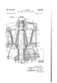
- Figure 1 is a vertical axial section
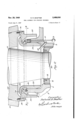
- Figure 2 is a partial vertical section on an enlarged scale
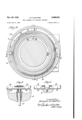
- Figure 3 is a section on the line 33 of Figure 2;
- Figure 4 is an enlarged section taken on line 4-4 of Figure 3;
- Figure 5 is an enlarged section taken on line 5--5 of Figure 3.
- l diagrammatically illustrates the top of the foundation upon which the crusher rests.
- 2 indicates the lower shell, shown as including a circumferential wall which may for convenience be in the form of a truncated dome. It is provided with an upper outwardly extending flange 3 and outwardly extending reinforcing ribs 4.
- 5 indicates any suitable rib structure adapted to center and support the inner bearing shell sleeve, or tube 6 which surrounds the below described eccentric. It is shown as having a bottom outwardly extending eaves portion l and an upper circumferential and generally cylindrical flange 3. Any suitable removable wear plates 9 may be used to protect the spider.
- H) is any suitable bearing sleeve within an outer shaft housing H.
- Rotatable in bearings 12 is the drive shaft [3 with its outer pulley l4 and bevel pinion l5.
- I6 is an eccentrically apertured sleeve rotatable within the sleeve or tube 6 and carrying at its lower end the bevel gear ll meshing with the pinion i5.
- rotation of the shaft I3 is effective to rotate the eccentric [6 within the sleeve or tube 6.
- the sleeve [6 is eccentrically apertured as at 18-
- the oil system does not of itself formpart of the present invention and will not be further described.
- an upper shell structure Positioned upon and above the lower shell 2 is an upper shell structure generally indicated as 36 which includes an outwardly extending lower flange 3i and an outwardly extending top flange- 32. It may interlock with the upper flange portion 3 of the lower shell, as at 33, whereby the upper shell structure is centered on the lower shell structure. gether by the tension rods or bolts 34, upwardly headed as at 3'5 and extending downwardly through the flange 3. They are provided with any suitable locking nuts 35.
- Any suitable spider structure not herein shown in detail but indicated at 31, carries a central knuckle or hub 38 with a lower ledge 39 and a bearing plate or plates 40 adapted to receive any suitable supporting sleeve 4
- the shaft I9 is suspended at its upper end from the spider, its lower end 26 extending into and being gyrated by the eccentrically apertured sleeve 5.
- the supporting connection including the plate 2!, permits gyration of the shaft about a center adjacent the upper end of the shaft and indi cated at X.
- any suitable head 45 upon which is positioned any suitable mantle 46, held in position by the top washer or thrust member 47.
- any suitable bowl concaves 53 Within the shell structure iii! are positioned any suitable bowl concaves 53. It will be understood that both the liner and the mantle structure may be made either as a single piece or in a plurality of pieces, depending upon the size of the crusher and the desire of the operator.
- I provide a simple and efiicient sealing structure which includes a sealing component 5
- an apron 55 which may be secured to the head, for example, by securing screws 56. It has an inwardly extending portion 5'! provided with an upwardly concave surface 58 which conforms to and engages the downwardly convex surface 54. It will be noticed that the apron 55 extends downwardly a substantial distance about the top flange 8 of the sleeve 6. Between the two members there is a. downwardly open space which constitutes a protecting area with which the outer junction of the surfaces 54 and 58 communicates. on the upper end of the flange 8 an annular spray ring 60 which may be supplied with water through any suitable duct 61.
- the spray member 60 may be provided with a plurality of spray apertures 62. These may be arranged, if desired, to direct spray generally downwardly and outwardly into the space surrounded by the apron 55. Thus the spray is directed across the space through which the dust would have to rise to penetrate the sealing surfaces.
- Sealing means for crushing machines and the like including concave and convex annular sealing members having opposed sealing surfaces in contact with one another, concentric spaced walls extending downwardly one from each sealing member defining an annular chamber, below, concentric with, and closed at its top by said members, means including one of said walls for also defining a relatively narrow annular passage, extending downwardly from the chamber and decreasing in width downwardly, one wall of the chamber being upwardly and inwardly inclined to overlie the passage and being located below the sealing surfaces, a spray pipe located in and extending about the entire angular extent of the chamber, concentric therewith and located above the passage and below the sealing surfaces,
- the pipe being apertured to direct a spray sheet outwardly across the upper end of the passage, below the sealing surfaces to impinge against the inclined wall.
Landscapes
- Engineering & Computer Science (AREA)
- Mechanical Engineering (AREA)
- Food Science & Technology (AREA)
- Crushing And Grinding (AREA)
Description
Nov. 29, 1949 R. R. SHAFTER 2,489,936
SEAL ASSEMBLY FOR GYRATORY CRUSHERS Filed June 9, 1947 3 Sheets-Sheet 1 Nov. 29, 1949 R. R. SHAFTER 2,489,936
SEAL ASSEMBLY FOR GYRATORY CRUSHERS Filed June 9, 1947 v 3 Sheets-Sheet 2 Fey 2 no J22 vefifor L R flu ZanaCZZJfia/Zer (fM/Wm Nov. 29, 1949 R. R. SHAFTER 2,489,936
SEAL ASSEMBLY FOR GYRATORY CRUSI-IERS Filed June 9, 1947 3 Sheets-Sheet 3 Z n were for .1? uZand .73. 5%a72er .fltfarrreya Patented Nov. 29, 1949 SEAL ASSEMBLY FOR GYRATORY CRUSHERS Ruland R. Shafter, Freeport, N. Y., assignor t Nordberg Manufacturing 00., Milwaukee, Wis., a corporation of Wisconsin Application June 9, 1947, Serial No. 753,466
1 Claim. 1
My invention relates to an improvement in gyratory crushers and has for one purpose to provide a gyratory crusher of simple and efficient structure.
Another purpose is to provide improved sealing and humidifying means for use in connection with a gyratory crusher.
Another purpose is to provide improved means for protecting the bearings of a gyratory crusher.
Another purpose is to provide an improved dust seal between the crushing space and the main shaft bearing.
Another purpose is to provide improved humidifying means for layin the dust created by the crushing action.
Other purposes will appear from time to time in the course of the specification and claim..
I illustrate my invention more or less diagrammatically in the accompanying drawings wherein:
Figure 1 is a vertical axial section;
Figure 2 is a partial vertical section on an enlarged scale;
Figure 3 is a section on the line 33 of Figure 2;
Figure 4 is an enlarged section taken on line 4-4 of Figure 3; and
Figure 5 is an enlarged section taken on line 5--5 of Figure 3.
Like parts are indicated by like symbols throughout the specification and drawings.
Referring to the drawings, l diagrammatically illustrates the top of the foundation upon which the crusher rests. 2 indicates the lower shell, shown as including a circumferential wall which may for convenience be in the form of a truncated dome. It is provided with an upper outwardly extending flange 3 and outwardly extending reinforcing ribs 4. 5 indicates any suitable rib structure adapted to center and support the inner bearing shell sleeve, or tube 6 which surrounds the below described eccentric. It is shown as having a bottom outwardly extending eaves portion l and an upper circumferential and generally cylindrical flange 3. Any suitable removable wear plates 9 may be used to protect the spider. H) is any suitable bearing sleeve within an outer shaft housing H. Rotatable in bearings 12 is the drive shaft [3 with its outer pulley l4 and bevel pinion l5. I6 is an eccentrically apertured sleeve rotatable within the sleeve or tube 6 and carrying at its lower end the bevel gear ll meshing with the pinion i5. Thus rotation of the shaft I3 is effective to rotate the eccentric [6 within the sleeve or tube 6.
The sleeve [6 is eccentrically apertured as at 18- However, the oil system does not of itself formpart of the present invention and will not be further described.
Positioned upon and above the lower shell 2 is an upper shell structure generally indicated as 36 which includes an outwardly extending lower flange 3i and an outwardly extending top flange- 32. It may interlock with the upper flange portion 3 of the lower shell, as at 33, whereby the upper shell structure is centered on the lower shell structure. gether by the tension rods or bolts 34, upwardly headed as at 3'5 and extending downwardly through the flange 3. They are provided with any suitable locking nuts 35. Any suitable spider structure, not herein shown in detail but indicated at 31, carries a central knuckle or hub 38 with a lower ledge 39 and a bearing plate or plates 40 adapted to receive any suitable supporting sleeve 4|, secured to the upper end of the shaft is by any suitable nut 42. Thus the shaft I9 is suspended at its upper end from the spider, its lower end 26 extending into and being gyrated by the eccentrically apertured sleeve 5. The supporting connection, including the plate 2!, permits gyration of the shaft about a center adjacent the upper end of the shaft and indi cated at X.
Mounted on the shaft 19 is any suitable head 45, upon which is positioned any suitable mantle 46, held in position by the top washer or thrust member 47. Within the shell structure iii! are positioned any suitable bowl concaves 53. It will be understood that both the liner and the mantle structure may be made either as a single piece or in a plurality of pieces, depending upon the size of the crusher and the desire of the operator.
It is vitally important to prevent the penetration of dust to the bearing surfaces between the tube 6 and the eccentric l6, and between the eccentric l6 and the shaft portion 29. I provide a simple and efiicient sealing structure which includes a sealing component 5| having a lower portion 52 extending within the top flange or housing portion 8. It also includes an upwardly and outwardly extending portion 53 having a downwardly convex spherical bearing or sealing The two shells may be held to-.-
3 surface 54 which is concentric with the center X about which the head gyrates.
Extending downwardly from the head is an apron 55 which may be secured to the head, for example, by securing screws 56. It has an inwardly extending portion 5'! provided with an upwardly concave surface 58 which conforms to and engages the downwardly convex surface 54. It will be noticed that the apron 55 extends downwardly a substantial distance about the top flange 8 of the sleeve 6. Between the two members there is a. downwardly open space which constitutes a protecting area with which the outer junction of the surfaces 54 and 58 communicates. on the upper end of the flange 8 an annular spray ring 60 which may be supplied with water through any suitable duct 61. Thus water, or any other suitable liquid, is sprayed into a restricted space surrounding the exterior junction of the opposed spherical sealing surfaces. Thus the relatively small amount of dust which penetrates in the space within the apron 55 in intercepted by the spray and flows downwardly, with the discharged water, thus giving substantial protection to the inner and outer bearings of the eccentric sleeve 16. The spray member 60 may be provided with a plurality of spray apertures 62. These may be arranged, if desired, to direct spray generally downwardly and outwardly into the space surrounded by the apron 55. Thus the spray is directed across the space through which the dust would have to rise to penetrate the sealing surfaces.
It will be realized that, whereas, I have described and illustrated a practical and operative device, nevertheless many changes may be made in the size, shape, number and disposition of parts without departing from the spirit of my invention. I therefore wish my description and I find it advantageous to position' drawings to be taken as in a broad sense illustrative or diagrammatic rather than as limiting me to my precise showing.
I claim:
Sealing means for crushing machines and the like, including concave and convex annular sealing members having opposed sealing surfaces in contact with one another, concentric spaced walls extending downwardly one from each sealing member defining an annular chamber, below, concentric with, and closed at its top by said members, means including one of said walls for also defining a relatively narrow annular passage, extending downwardly from the chamber and decreasing in width downwardly, one wall of the chamber being upwardly and inwardly inclined to overlie the passage and being located below the sealing surfaces, a spray pipe located in and extending about the entire angular extent of the chamber, concentric therewith and located above the passage and below the sealing surfaces,
- means for supplying fluid under pressure to the.
pipe, the pipe being apertured to direct a spray sheet outwardly across the upper end of the passage, below the sealing surfaces to impinge against the inclined wall.
RULAND R. SHAFIER.
REFERENCES CITED The following references are of record in the file of this patent:
UNITED STATES PATENTS Number Name Date 744,636 Small Nov. 17, 1903 1,660,589 Aulman Feb. 28, 1928 1,791,584 Symons Feb. 10, 1931 2,000,385 Gruender May 7, 1935 2,054,326 Jacobson Sept. 15, 1936 2,148,682 Campbell Feb. 28, 1939
Priority Applications (1)
| Application Number | Priority Date | Filing Date | Title |
|---|---|---|---|
| US753466A US2489936A (en) | 1947-06-09 | 1947-06-09 | Seal assembly for gyratory crushers |
Applications Claiming Priority (1)
| Application Number | Priority Date | Filing Date | Title |
|---|---|---|---|
| US753466A US2489936A (en) | 1947-06-09 | 1947-06-09 | Seal assembly for gyratory crushers |
Publications (1)
| Publication Number | Publication Date |
|---|---|
| US2489936A true US2489936A (en) | 1949-11-29 |
Family
ID=25030753
Family Applications (1)
| Application Number | Title | Priority Date | Filing Date |
|---|---|---|---|
| US753466A Expired - Lifetime US2489936A (en) | 1947-06-09 | 1947-06-09 | Seal assembly for gyratory crushers |
Country Status (1)
| Country | Link |
|---|---|
| US (1) | US2489936A (en) |
Cited By (6)
| Publication number | Priority date | Publication date | Assignee | Title |
|---|---|---|---|---|
| US2832547A (en) * | 1954-04-05 | 1958-04-29 | Joseph E Kennedy | Geared gyratory crushers |
| US2860837A (en) * | 1953-08-11 | 1958-11-18 | Nordberg Manufacturing Co | Crusher main frame |
| EP2774683A1 (en) | 2013-03-08 | 2014-09-10 | Sandvik Intellectual Property AB | Gyratory crusher spider arm shield |
| EP2859951A1 (en) | 2013-10-11 | 2015-04-15 | Sandvik Intellectual Property AB | Gyratory crusher spider arm shields |
| US10434516B2 (en) | 2014-10-09 | 2019-10-08 | Sandvik Intellectual Property Ab | Spider wall shield |
| US10751721B2 (en) | 2014-10-09 | 2020-08-25 | Sandvik Intellectual Property Ab | Spider arm shield |
Citations (6)
| Publication number | Priority date | Publication date | Assignee | Title |
|---|---|---|---|---|
| US744636A (en) * | 1903-07-08 | 1903-11-17 | Perry Small | Bearing for dredging-machines. |
| US1660589A (en) * | 1928-02-28 | Gbavel-washilsra machine | ||
| US1791584A (en) * | 1929-12-09 | 1931-02-10 | Nordberg Manufacturing Co | Cone crusher |
| US2000385A (en) * | 1932-05-27 | 1935-05-07 | Nordberg Manufacturing Co | Bearing protection device |
| US2054326A (en) * | 1933-11-27 | 1936-09-15 | Nordberg Manufacturing Co | Water seal for use with crushing machinery |
| US2148682A (en) * | 1935-09-13 | 1939-02-28 | Pennsyivania Crusher Company | Crusher |
-
1947
- 1947-06-09 US US753466A patent/US2489936A/en not_active Expired - Lifetime
Patent Citations (6)
| Publication number | Priority date | Publication date | Assignee | Title |
|---|---|---|---|---|
| US1660589A (en) * | 1928-02-28 | Gbavel-washilsra machine | ||
| US744636A (en) * | 1903-07-08 | 1903-11-17 | Perry Small | Bearing for dredging-machines. |
| US1791584A (en) * | 1929-12-09 | 1931-02-10 | Nordberg Manufacturing Co | Cone crusher |
| US2000385A (en) * | 1932-05-27 | 1935-05-07 | Nordberg Manufacturing Co | Bearing protection device |
| US2054326A (en) * | 1933-11-27 | 1936-09-15 | Nordberg Manufacturing Co | Water seal for use with crushing machinery |
| US2148682A (en) * | 1935-09-13 | 1939-02-28 | Pennsyivania Crusher Company | Crusher |
Cited By (9)
| Publication number | Priority date | Publication date | Assignee | Title |
|---|---|---|---|---|
| US2860837A (en) * | 1953-08-11 | 1958-11-18 | Nordberg Manufacturing Co | Crusher main frame |
| US2832547A (en) * | 1954-04-05 | 1958-04-29 | Joseph E Kennedy | Geared gyratory crushers |
| EP2774683A1 (en) | 2013-03-08 | 2014-09-10 | Sandvik Intellectual Property AB | Gyratory crusher spider arm shield |
| WO2014135306A1 (en) | 2013-03-08 | 2014-09-12 | Sandvik Intellectual Property Ab | Gyratory crusher spider arm shield |
| US9358545B2 (en) | 2013-03-08 | 2016-06-07 | Sandvik Intellectual Property Ab | Gyratory crusher spider arm shield |
| EP2859951A1 (en) | 2013-10-11 | 2015-04-15 | Sandvik Intellectual Property AB | Gyratory crusher spider arm shields |
| US9592512B2 (en) | 2013-10-11 | 2017-03-14 | Sandvik Intellectual Property Ab | Gyratory crusher spider arm shields |
| US10434516B2 (en) | 2014-10-09 | 2019-10-08 | Sandvik Intellectual Property Ab | Spider wall shield |
| US10751721B2 (en) | 2014-10-09 | 2020-08-25 | Sandvik Intellectual Property Ab | Spider arm shield |
Similar Documents
| Publication | Publication Date | Title |
|---|---|---|
| US2079882A (en) | Crusher and pressure-exerting machinery | |
| US2509920A (en) | Feeding device for gyratory crushers | |
| US2359987A (en) | Pedestal type crusher | |
| US3160354A (en) | Comminution device | |
| US3080126A (en) | Bearing seals for gyratory crushers | |
| US2190036A (en) | Ore crusher | |
| US2134876A (en) | Dust seal for crushing machines | |
| US2185528A (en) | Cone crusher | |
| US1656756A (en) | Ore-grinding machine | |
| US2158779A (en) | Crusher | |
| US2305616A (en) | Shaftless gyratory cone crusher | |
| US2468342A (en) | Gyratory crusher with wedge secured bowl liner | |
| US1670714A (en) | Attrition grinder | |
| US2621860A (en) | Feed plate for gyratory crushers | |
| US2634061A (en) | Gyratory crusher | |
| US3396916A (en) | Fluid pressure operated adjustment and release for gyratory crushers and the like | |
| US2893649A (en) | Grinding mill | |
| US1863529A (en) | Crushing apparatus | |
| US2963232A (en) | Grinder | |
| US1553333A (en) | Crushing apparatus | |
| US2590795A (en) | Gyratory crusher | |
| US2670142A (en) | Attrition mill | |
| US964102A (en) | Centrifugal pulverizer. | |
| US2017598A (en) | Means for reducing and grading ores | |
| US2254425A (en) | Crusher |