US2488930A - Amusement device - Google Patents
Amusement device Download PDFInfo
- Publication number
- US2488930A US2488930A US571326A US57132645A US2488930A US 2488930 A US2488930 A US 2488930A US 571326 A US571326 A US 571326A US 57132645 A US57132645 A US 57132645A US 2488930 A US2488930 A US 2488930A
- Authority
- US
- United States
- Prior art keywords
- cab
- pipe
- suspended
- flight
- lever
- Prior art date
- Legal status (The legal status is an assumption and is not a legal conclusion. Google has not performed a legal analysis and makes no representation as to the accuracy of the status listed.)
- Expired - Lifetime
Links
Images
Classifications
-
- A—HUMAN NECESSITIES
- A63—SPORTS; GAMES; AMUSEMENTS
- A63G—MERRY-GO-ROUNDS; SWINGS; ROCKING-HORSES; CHUTES; SWITCHBACKS; SIMILAR DEVICES FOR PUBLIC AMUSEMENT
- A63G1/00—Roundabouts
- A63G1/28—Roundabouts with centrifugally-swingable suspended seats
Definitions
- the present invention relates generally to amusement devices, but more particularly to a type of device which is in the form of a series of passenger carrying cabs freely suspended from an overhead revolving structure in which controls may be manipulated by the operator so that the cab proper and the flight varying means or wings immovably carried by the cab may be deviated or angularly disposed to change or vary the course of the flight of the cab from its normal course caused by the centrifugal action of the revolving structure.
- Another object of the invention is to provide a novel and improved type of amusement device of a quickly detachable or knock-down structure which will expedite the setting up or disassembling of the same in compact form for transporting from one place to another.
- a further object of the invention is to provide a novel and improved amusement device of the passenger carrying cab type freely suspended from an overhanging revolving structure and having flight-varying means or wing surfaces rigidly attached thereto in combination with a manually operable means within easy reach of the operator to deviate the wing surface and the cab with respect to supporting or suspended means attached to the revolving structure.
- Fig. 1 is a fragmentary view showing one of the angularly disposed arms of a revolving structure having one of my improved types of passenger carrying cabs suspended therefrom;
- Fig. 2 is an enlarged side elevational view showing the construction of my improved passenger carrying cab
- Fig. 3 is a cross sectional view taken on the line 3-3 in Fig. 2;
- Fig. 4 is a broken front elevational view showing the supporting structure for each of the passenger carrying cabs.
- Fig. 5 is a cross sectional view taken on the line 5-5 in Fig. 2.
- a more or less conventional type of revolving structure which consists of a plurality of angularly and upwardly inclined beams or arms, only one of which is shown in Fig. 1 of the drawings, and generally designated by the reference character I0.
- the revolving structure may consist of any number of arms depending upon the size and diameter and are all secured together by suitable structural steel so that they revolve about a fixed vertical pivot
- the arm l0 consists preferably of two outwardly and upwardly extending I-beams I l which converge towards the pivot of the revolving structure and diverge upwardly and outwardly as shown in Fig. 1 of the drawings.
- the I-beams are suitably braced by transverse angularly disposed braces or angle members l2.
- Welded or otherwise secured to the outer ends of the I-beams II are vertically spaced apart and aligned apertured plates or brackets I3.
- Detachably mounted between each of the plates l3 of the respective I-beams H is a horizontal pipe [4 which has its opposite ends secured to the respective brackets l3 by means of vertical pins IS.
- the pins [5 are retained in position by the cotter pins [6.
- Welded in the approximate center of the pipe M are horizontally spaced apart and aligned apertured brackets or hinge plates l1. Pivoted between the hinge plates I!
- the cable structure 25 and 25 rigidly braces the suspended pipe against forward or rearward movement with respect to the transverse pipe I4, but permits the suspended structure to swing about the axis of the pins l3 and 2
- a passenger carrying cab Detachably and oscillatably supported on the lower end of the pipe I9 is a passenger carrying cab generally indicated by the reference character 28.
- the passenger carrying cab in this instance comprises suitable front and rear vertical frame members 29 and 3ll'respectively of U-shaped cross section, which are rigidly secured to the floor or bottom 3
- the structure which detachably and oscillatably supports the individual passenger cabs on the lower end of the pipe I9 includes a metal plug 4i which has one end projecting internally of the lower end of the pipe I9 and is preferably welded therein as shown at 42.
- the lower end of the plug 41 has an annular flange as shown at 43 so as to form in effect an annular recess 44 for the reception of a split washer as shown at 45.
- the split washer 45 is held from displacement in the recess 44 by a circular member washer 46, which has a downwardly projecting fiange 41 so as to engage the outer periphery of the split washer 45 and prevent its displacement therefrom.
- Seated or resting upon the washer 66 is an anti-friction bearing generally indicated by the reference character 48.
- the inner race way of the anti-friction bearing seats on the washer 46 and the outer race way supports the thrust load by engagement with an internal annular flange orring 49, which in turn, is welded to the internal surface of the casing 36 as
- the upper portion of the bearing casing 36 is 1 supported in position by a bronze bushing 51 which is supported in place to form a journal for the external surface of the pipe i9 by a filler or ring 52 which in turn, is welded internally of the casing 36 adjacent the upper end thereof.
- the casing is held from displacement upwardly with respect to the pipe by a safety pin 53 which extends through suitable aligned apertures 54 in the pipe I! and is held from displacement with respect to the pipe by means of a cotter pin 55.
- the lower end of the bearing casing is enclosed by a removable snap-on cap, generally indicated by the reference character 56.
- the flight of the passenger carrying cab is deviated from its normal course and under the control of the operator by oscillating the cab 23 and flight varying means 32' and 33 as a whole with respect to the suspended pipe by reason of the fact that the flight varying means or wings may thus be presented at various angles during the revolving motion of the cab. This is especially true when the centrifugal force of the revolving structure reaches the point where the plane surfaces of the wings 32 and 33 approach a horizontal position.
- This control mechanism which extends to within easy reach of the operator in the cab includes a forwardly projecting arm 5? which is welded-to the pipe l9 as shown at 58.
- the forward end of the arm 51 has a ball 53 formed thereon so as to form part of a ball and socket connection generally indicated by the reference character 6
- This ball and socket connection 62 includes a ball 63 formed on the upper end of a lever 64.
- the two ball and socket connections are of the conventional constructioniland include a threaded socket plug 64 mounted in threaded engagement with the socket. The inner end of the plug 64 is complementary to the ball and retains the ball in its socket.
- a lever 64' has its intermediate portion pivoted by means of a pin 65 mounted in the apertured aligned brackets 66 which have their inner ends welded to one of the side plates 36 as shown at 6?. The pin 65 is held in position by a cotter pin 68.
- the lower end of the lever 6 below the pivot 65 is provided with a bifurcated portion 69 having aligned apertures therein for pivotally supporting a hand lever 10 by a pin iii.
- the lever 16 may be swung from the broken line position in Fig. 2 of the drawings to the full line position shown therein to permit easy ingress and egress of the passengers to and from the cab.
- the forward and rearward swinging of the lever H3 is permitted by the pivot on the pin 1 l, but when the cabas a whole is to be swung with respect to the pipe iii the lever in that case is moved laterally from side to side so that the lever 76 and 64 as a whole swing about the pin 65 as an axis.
- to the rigidarm 5'! of the pipe l9 permits the cab to be actuated or oscillated on its pivotal support to deviate it and thereby control the effectiveness of the flight varying means or wings 32 and 33.
- An amusement device comprising a revolving structure, suspended means supported from said structure, an oscillatable passenger carrying cab journaled on the free end of said suspended means, flight varying means rigidly attached to said passenger carrying cab, and means operable from said cab and operatively connected to said suspended means for oscillating said cab about said suspended means.
- An amusement device comprising a revolving structure, suspended means supported from said structure, an oscillatable passenger carrying cab journaled on the free end of said suspended means, flight varying means rigidly attached to said passenger carrying cab, and manually controlled connections between said suspended means and said passenger cab and operable from said cab for angularly disposing said cab with respect to said suspended means.
- An amusement device comprising a revolving structure, suspended means supported from said structure, a passenger carrying cab journaled on the lower end of said suspended means, flight varying means located substantially in the longitudinal center of said cab and rigidly attached thereto, and means for angularly displacing said cab with respect to said suspended means for varying the flight of said cab.
- An amusement device comprising a revolving structure, suspended means supported from said structure, a passenger carrying cab journaled on the lower end of said suspended means, flight varying means located substantially in the longitudinal center of said cab and rigidly attached thereto, and manually controlled means for angularly displacing said cab with respect to said suspended means for varying the flight of said cab.
- An amusement device comprising a revolving structure, suspended means supported from said structure, a passenger carrying cab journaled on the lower end of said suspended means, flight varying means located substantially in the longitudinal center of said cab and rigidly attached thereto, a hand operable lever pivoted to said cab, and operative connections between said lever and said suspended means whereby upon the manipulation of said lever said cab may be angularly displaced with respect to said suspended means.
- An amusement device comprising a revolving structure having radially projecting arms, a pipe pivotally suspended from said arms, a passenger carrying cab pivoted to the lower end of said pipe,
- flight varying means in the form of wing surfaces rigidly secured to said cab in the approximate longitudinal center thereof, and a lever pivoted to said cab and operatively connected to said-pipe whereby upon the manipulation of said lever the flight of said cab may be deviated from its normal course of travel.
- An amusement device comprising a revolving structure having radially projecting arms, a pipe pivotally suspended from said arms, a passenger carrying cab pivoted to the lower end of said pipe, flight varying means in the form of wing surfaces rigidly secured to said cab in the approximate longitudinal center thereof, a lever pivoted to said cab and operable therefrom, an arm rigidly secured to said pipe, and a link forming the connection between said lever and said last named arm for manually actuating said cab with respect to said pipe.
- An amusement device comprising a revolving overhead structure, cab supporting means pivoted to said structure, a cab pivoted to said supporting means, flight varying means rigidly secured to said cab, and means carried by said cab for manually actuating said cab about its pivot.
- An amusement device comprising a revolving structure, a pipe supported horizontally on said structure, a suspended pipe pivoted to said first named pipe, a passenger carrying cab detachably connected and pivoted on the lower end of said first named pipe, longitudinally extending wing surfaces secured to said cab, and manually operable means including a lever operable from said cab and connected to said suspended pipe for angularly displacing said cab with respect to said suspended pipe.
- An amusement device comprising a revolving structure, a pipe supported horizontally on said structure, a suspended pipe pivoted to said first named pipe, a passenger carrying cab detachably connected and pivoted on the lower end of said first named pipe, longitudinally extending wing surfaces secured to said cab, a lever pivoted to said cab within easy reach of the operator in said cab, and connections between said lever and said suspended pipe whereby upon the manipulation of said lever said cab may be actuated about its pivot on said suspended pipe.
Description
New. 22, 1949 D. H. PARKERsofi, JR 2,488,930
AMUSEMENT DEVICE Filed Jan. 4, 1945 m I H 2 Sheets-Sheet l INVENTOR.
J0 Parkeraan, @W
Nov. 22, 1949 I; H. PARKERSON, JR 2,488,930
AMUSEMENT DEVI CE Filed Jan. 4, 1945 2 Sheets-Sheet 2 INVENTOR.
BY 3 Qg Patented Nov. 22, 1949 AMUSEMENT DEVICE Donald H. Parkerson, J r., Chicago, Ill., assignor to Alvin Bisch, Chicago, Ill.
Application January 4, 1945, Serial No. 571,326
10 Claims.
The present invention relates generally to amusement devices, but more particularly to a type of device which is in the form of a series of passenger carrying cabs freely suspended from an overhead revolving structure in which controls may be manipulated by the operator so that the cab proper and the flight varying means or wings immovably carried by the cab may be deviated or angularly disposed to change or vary the course of the flight of the cab from its normal course caused by the centrifugal action of the revolving structure.
Another object of the invention is to provide a novel and improved type of amusement device of a quickly detachable or knock-down structure which will expedite the setting up or disassembling of the same in compact form for transporting from one place to another.
A further object of the invention is to provide a novel and improved amusement device of the passenger carrying cab type freely suspended from an overhanging revolving structure and having flight-varying means or wing surfaces rigidly attached thereto in combination with a manually operable means within easy reach of the operator to deviate the wing surface and the cab with respect to supporting or suspended means attached to the revolving structure.
These and other objects are accomplished by providing a construction and an arrangement of the various parts in the manner hereinafter described and particularly pointed out in the appended claims.
Referring to the drawings:
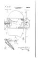
Fig. 1 is a fragmentary view showing one of the angularly disposed arms of a revolving structure having one of my improved types of passenger carrying cabs suspended therefrom;
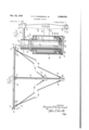
Fig. 2 is an enlarged side elevational view showing the construction of my improved passenger carrying cab;
Fig. 3 is a cross sectional view taken on the line 3-3 in Fig. 2;
Fig. 4 is a broken front elevational view showing the supporting structure for each of the passenger carrying cabs; and
Fig. 5 is a cross sectional view taken on the line 5-5 in Fig. 2.
In carrying out my invention, I have shown the same in connection with a more or less conventional type of revolving structure which consists of a plurality of angularly and upwardly inclined beams or arms, only one of which is shown in Fig. 1 of the drawings, and generally designated by the reference character I0. Since the revolving structure may consist of any number of arms depending upon the size and diameter and are all secured together by suitable structural steel so that they revolve about a fixed vertical pivot, the arm l0 consists preferably of two outwardly and upwardly extending I-beams I l which converge towards the pivot of the revolving structure and diverge upwardly and outwardly as shown in Fig. 1 of the drawings. The I-beams are suitably braced by transverse angularly disposed braces or angle members l2. Welded or otherwise secured to the outer ends of the I-beams II are vertically spaced apart and aligned apertured plates or brackets I3. Detachably mounted between each of the plates l3 of the respective I-beams H is a horizontal pipe [4 which has its opposite ends secured to the respective brackets l3 by means of vertical pins IS. The pins [5 are retained in position by the cotter pins [6. Welded in the approximate center of the pipe M are horizontally spaced apart and aligned apertured brackets or hinge plates l1. Pivoted between the hinge plates I! by means of a bolt I8 is a suspended pipe or shaft l9. Welded adjacent the opposite ends of the pipe M are angularly and inwardly disposed plates or hinge brackets 20. Pivoted to each of the plates 20 by means of bolts 2! are eye brackets 22. The pivots 2| of each of the eye brackets 22 are in horizontal alignment with the pivot I8 of the pipe I9. Welded apertured plates 24. Connecting the opposite proximate center thereof are apertured plates 23. Secured to the opposite sides of the pipe l8 adjacent the lower end thereof are similar apertured plates 24. Connecting the opposite plates 23 and 24 with the respective eye brackets 22, are cables or rods 25 and 26. These cables are rigidly secured in place by cable clamps generally indicated by the reference character 21. From the above description is will be readily seen that the cable structure 25 and 25 rigidly braces the suspended pipe against forward or rearward movement with respect to the transverse pipe I4, but permits the suspended structure to swing about the axis of the pins l3 and 2| as will hereinafter be more fully described.
Detachably and oscillatably supported on the lower end of the pipe I9 is a passenger carrying cab generally indicated by the reference character 28. The passenger carrying cab in this instance comprises suitable front and rear vertical frame members 29 and 3ll'respectively of U-shaped cross section, which are rigidly secured to the floor or bottom 3|. Located in the rear of the cab against the vertical frame member 30.
members 34 and 35 are welded to a vertically dis-1 A posed cylindrical casin generally indicated by thereference character 36. Welded to the cylin-' drical casing 36 are rear channel shaped mem bers 31 and 38, which are arranged parallel and in the plane of the respective channel'members 34 and 35. The rear ends of the channelmem bers 31 and 38 are welded to the vertical U-shaped or channel member of the main frame. Mounted between the vertical and opposite legs of the respective channel members 34, 35, 3'! and 38 are opposite spacer plates 39 and 4B. 4
The structure which detachably and oscillatably supports the individual passenger cabs on the lower end of the pipe I9 includes a metal plug 4i which has one end projecting internally of the lower end of the pipe I9 and is preferably welded therein as shown at 42. The lower end of the plug 41 has an annular flange as shown at 43 so as to form in effect an annular recess 44 for the reception of a split washer as shown at 45. The split washer 45 is held from displacement in the recess 44 by a circular member washer 46, which has a downwardly projecting fiange 41 so as to engage the outer periphery of the split washer 45 and prevent its displacement therefrom. Seated or resting upon the washer 66 is an anti-friction bearing generally indicated by the reference character 48. The inner race way of the anti-friction bearing seats on the washer 46 and the outer race way supports the thrust load by engagement with an internal annular flange orring 49, which in turn, is welded to the internal surface of the casing 36 as shown at 56.
The upper portion of the bearing casing 36 is 1 supported in position by a bronze bushing 51 which is supported in place to form a journal for the external surface of the pipe i9 by a filler or ring 52 which in turn, is welded internally of the casing 36 adjacent the upper end thereof. The casing is held from displacement upwardly with respect to the pipe by a safety pin 53 which extends through suitable aligned apertures 54 in the pipe I!) and is held from displacement with respect to the pipe by means of a cotter pin 55. The lower end of the bearing casing is enclosed by a removable snap-on cap, generally indicated by the reference character 56.
From the above description it will be seen that in order to remove the cab as a whole from the suspended pipe Hi, all that is necessary to do is to remove the cap 56, remove the safety pin and lift the cab and casing 36 vertically upwardly on the pipe [9 to a position in which the split washer can be removed by displacing the flanged washer 46, after whichthe cab, together with the bearing casing 36 may beremoved from the pipe [9.
The flight of the passenger carrying cab is deviated from its normal course and under the control of the operator by oscillating the cab 23 and flight varying means 32' and 33 as a whole with respect to the suspended pipe by reason of the fact that the flight varying means or wings may thus be presented at various angles during the revolving motion of the cab. This is especially true when the centrifugal force of the revolving structure reaches the point where the plane surfaces of the wings 32 and 33 approach a horizontal position. This control mechanism which extends to within easy reach of the operator in the cab includes a forwardly projecting arm 5? which is welded-to the pipe l9 as shown at 58. The forward end of the arm 51 has a ball 53 formed thereon so as to form part of a ball and socket connection generally indicated by the reference character 6|] of a link connection 6|.
indicated by the reference character 62. This ball and socket connection 62 includes a ball 63 formed on the upper end of a lever 64. The two ball and socket connections are of the conventional constructioniland include a threaded socket plug 64 mounted in threaded engagement with the socket. The inner end of the plug 64 is complementary to the ball and retains the ball in its socket. A lever 64' has its intermediate portion pivoted by means of a pin 65 mounted in the apertured aligned brackets 66 which have their inner ends welded to one of the side plates 36 as shown at 6?. The pin 65 is held in position by a cotter pin 68. The lower end of the lever 6 below the pivot 65 is provided with a bifurcated portion 69 having aligned apertures therein for pivotally supporting a hand lever 10 by a pin iii. The lever 16 may be swung from the broken line position in Fig. 2 of the drawings to the full line position shown therein to permit easy ingress and egress of the passengers to and from the cab. It will be obvious that the forward and rearward swinging of the lever H3 is permitted by the pivot on the pin 1 l, but when the cabas a whole is to be swung with respect to the pipe iii the lever in that case is moved laterally from side to side so that the lever 76 and 64 as a whole swing about the pin 65 as an axis. When thus operated, the connecting links 6| to the rigidarm 5'! of the pipe l9 permits the cab to be actuated or oscillated on its pivotal support to deviate it and thereby control the effectiveness of the flight varying means or wings 32 and 33.
Summarizing the advantages and functions of operation of my improved amusement device, it will be obvious that by removing the pin 65 and disconnecting the lever 64 from the brackets 65 and then removing the cap 56 on the bearing shell 36 and subsequently removing the safety pin '53 and slightly raising the shell'36 upwardly so that the split washer 45 may be removed from below the flanged washer 46, the cab as a whole may be removed from the supporting pipe IS with little or no effort. Similarly, by removing the pins 15 from the opposite ends of the pipe I4, the supporting structure of the cab maybe readily removed from the revolving beam in of the revolving structure to thereby provide a quickly collapsible or easily set up structure. This, in
effect, provides a very efficient and portable amusement device.
It will also be observed from the above description that by having the flight varying means detachably, but immovably secured to the passenger cab with the cab and flight means movable as a whole with respect to its supporting means, full advantage of the surfaces of the flightmeans.
maybe taken by the operator to vary the flight. of the passenger cab during its revolving course or travel. I
While in the above specification I have described one embodiment which my invention may assume in practice, it will of course be understood that the same is capable of modification and that modification may be made without departing from the spirit and scope of the invention as expressed in the following claims.
What I claim as my invention and desire to secure by Letters Patent is:
1. An amusement device comprising a revolving structure, suspended means supported from said structure, an oscillatable passenger carrying cab journaled on the free end of said suspended means, flight varying means rigidly attached to said passenger carrying cab, and means operable from said cab and operatively connected to said suspended means for oscillating said cab about said suspended means.
2. An amusement device comprising a revolving structure, suspended means supported from said structure, an oscillatable passenger carrying cab journaled on the free end of said suspended means, flight varying means rigidly attached to said passenger carrying cab, and manually controlled connections between said suspended means and said passenger cab and operable from said cab for angularly disposing said cab with respect to said suspended means.
3. An amusement device comprising a revolving structure, suspended means supported from said structure, a passenger carrying cab journaled on the lower end of said suspended means, flight varying means located substantially in the longitudinal center of said cab and rigidly attached thereto, and means for angularly displacing said cab with respect to said suspended means for varying the flight of said cab.
4. An amusement device comprising a revolving structure, suspended means supported from said structure, a passenger carrying cab journaled on the lower end of said suspended means, flight varying means located substantially in the longitudinal center of said cab and rigidly attached thereto, and manually controlled means for angularly displacing said cab with respect to said suspended means for varying the flight of said cab.
5. An amusement device comprising a revolving structure, suspended means supported from said structure, a passenger carrying cab journaled on the lower end of said suspended means, flight varying means located substantially in the longitudinal center of said cab and rigidly attached thereto, a hand operable lever pivoted to said cab, and operative connections between said lever and said suspended means whereby upon the manipulation of said lever said cab may be angularly displaced with respect to said suspended means.
6. An amusement device comprising a revolving structure having radially projecting arms, a pipe pivotally suspended from said arms, a passenger carrying cab pivoted to the lower end of said pipe,
flight varying means in the form of wing surfaces rigidly secured to said cab in the approximate longitudinal center thereof, and a lever pivoted to said cab and operatively connected to said-pipe whereby upon the manipulation of said lever the flight of said cab may be deviated from its normal course of travel.
7. An amusement device comprising a revolving structure having radially projecting arms, a pipe pivotally suspended from said arms, a passenger carrying cab pivoted to the lower end of said pipe, flight varying means in the form of wing surfaces rigidly secured to said cab in the approximate longitudinal center thereof, a lever pivoted to said cab and operable therefrom, an arm rigidly secured to said pipe, and a link forming the connection between said lever and said last named arm for manually actuating said cab with respect to said pipe.
8. An amusement device comprising a revolving overhead structure, cab supporting means pivoted to said structure, a cab pivoted to said supporting means, flight varying means rigidly secured to said cab, and means carried by said cab for manually actuating said cab about its pivot.
9. An amusement device comprising a revolving structure, a pipe supported horizontally on said structure, a suspended pipe pivoted to said first named pipe, a passenger carrying cab detachably connected and pivoted on the lower end of said first named pipe, longitudinally extending wing surfaces secured to said cab, and manually operable means including a lever operable from said cab and connected to said suspended pipe for angularly displacing said cab with respect to said suspended pipe.
10. An amusement device comprising a revolving structure, a pipe supported horizontally on said structure, a suspended pipe pivoted to said first named pipe, a passenger carrying cab detachably connected and pivoted on the lower end of said first named pipe, longitudinally extending wing surfaces secured to said cab, a lever pivoted to said cab within easy reach of the operator in said cab, and connections between said lever and said suspended pipe whereby upon the manipulation of said lever said cab may be actuated about its pivot on said suspended pipe.
DONALD H. PARKERSON, JR.
REFERENCES CITED The following references are of record in the file of this patent:
UNITED STATES PATENTS Number Name Date 643,675 Murdy Feb. 20, 1900 1,965,039 Hunt July 3, 1934 2,142,169 Bisch Jan. 3, 1939 2,162,877 Bisch June 20, 1939
Priority Applications (1)
| Application Number | Priority Date | Filing Date | Title |
|---|---|---|---|
| US571326A US2488930A (en) | 1945-01-04 | 1945-01-04 | Amusement device |
Applications Claiming Priority (1)
| Application Number | Priority Date | Filing Date | Title |
|---|---|---|---|
| US571326A US2488930A (en) | 1945-01-04 | 1945-01-04 | Amusement device |
Publications (1)
| Publication Number | Publication Date |
|---|---|
| US2488930A true US2488930A (en) | 1949-11-22 |
Family
ID=24283228
Family Applications (1)
| Application Number | Title | Priority Date | Filing Date |
|---|---|---|---|
| US571326A Expired - Lifetime US2488930A (en) | 1945-01-04 | 1945-01-04 | Amusement device |
Country Status (1)
| Country | Link |
|---|---|
| US (1) | US2488930A (en) |
Citations (4)
| Publication number | Priority date | Publication date | Assignee | Title |
|---|---|---|---|---|
| US643675A (en) * | 1899-06-03 | 1900-02-20 | Thomas Murdy | Merry-go-round. |
| US1965039A (en) * | 1931-08-10 | 1934-07-03 | Harold H Hunt | Amusement device |
| US2142169A (en) * | 1934-07-21 | 1939-01-03 | Bisch Roeco Amusement Co | Amusement device |
| US2162877A (en) * | 1937-02-20 | 1939-06-20 | Bisch Alvin | Amusement device |
-
1945
- 1945-01-04 US US571326A patent/US2488930A/en not_active Expired - Lifetime
Patent Citations (4)
| Publication number | Priority date | Publication date | Assignee | Title |
|---|---|---|---|---|
| US643675A (en) * | 1899-06-03 | 1900-02-20 | Thomas Murdy | Merry-go-round. |
| US1965039A (en) * | 1931-08-10 | 1934-07-03 | Harold H Hunt | Amusement device |
| US2142169A (en) * | 1934-07-21 | 1939-01-03 | Bisch Roeco Amusement Co | Amusement device |
| US2162877A (en) * | 1937-02-20 | 1939-06-20 | Bisch Alvin | Amusement device |
Similar Documents
| Publication | Publication Date | Title |
|---|---|---|
| US2759737A (en) | Vertically adjustable truck trailer | |
| US2309750A (en) | Earth mover | |
| US3456943A (en) | Amusement ride apparatus and method | |
| US2294166A (en) | Amusement device | |
| US2857993A (en) | Collapsible oil well derrick | |
| US2547152A (en) | Multiplane rotating movement for aerial amusement rides | |
| US2488930A (en) | Amusement device | |
| GB831338A (en) | Merry-go-round | |
| US2537399A (en) | Horizontal axis roundabout | |
| KR101776833B1 (en) | Platform rotating apparatus for high place operation car | |
| US2267705A (en) | Oil field apparatus | |
| CN205059371U (en) | Automatic control safe strutting arrangement | |
| US2274956A (en) | Operating mechanism for amusement devices | |
| US2142169A (en) | Amusement device | |
| US1885295A (en) | Mining machine | |
| US2469069A (en) | Trolley suspended playground device | |
| US3222061A (en) | Portable amusement ride | |
| US2503604A (en) | Mast structure | |
| US2452896A (en) | Cement mixer | |
| US1289427A (en) | Locomotive-crane. | |
| US1435984A (en) | Amusement device | |
| US2162877A (en) | Amusement device | |
| US2525458A (en) | Collapsible roundabout | |
| US2605134A (en) | Dumping trailer | |
| US3078090A (en) | Amusement ride |