US2488027A - Method and apparatus for catalytic conversion - Google Patents
Method and apparatus for catalytic conversion Download PDFInfo
- Publication number
- US2488027A US2488027A US376763A US37676341A US2488027A US 2488027 A US2488027 A US 2488027A US 376763 A US376763 A US 376763A US 37676341 A US37676341 A US 37676341A US 2488027 A US2488027 A US 2488027A
- Authority
- US
- United States
- Prior art keywords
- catalyst
- zone
- stream
- column
- regeneration
- Prior art date
- Legal status (The legal status is an assumption and is not a legal conclusion. Google has not performed a legal analysis and makes no representation as to the accuracy of the status listed.)
- Expired - Lifetime
Links
Images
Classifications
-
- C—CHEMISTRY; METALLURGY
- C10—PETROLEUM, GAS OR COKE INDUSTRIES; TECHNICAL GASES CONTAINING CARBON MONOXIDE; FUELS; LUBRICANTS; PEAT
- C10G—CRACKING HYDROCARBON OILS; PRODUCTION OF LIQUID HYDROCARBON MIXTURES, e.g. BY DESTRUCTIVE HYDROGENATION, OLIGOMERISATION, POLYMERISATION; RECOVERY OF HYDROCARBON OILS FROM OIL-SHALE, OIL-SAND, OR GASES; REFINING MIXTURES MAINLY CONSISTING OF HYDROCARBONS; REFORMING OF NAPHTHA; MINERAL WAXES
- C10G11/00—Catalytic cracking, in the absence of hydrogen, of hydrocarbon oils
- C10G11/14—Catalytic cracking, in the absence of hydrogen, of hydrocarbon oils with preheated moving solid catalysts
- C10G11/18—Catalytic cracking, in the absence of hydrogen, of hydrocarbon oils with preheated moving solid catalysts according to the "fluidised-bed" technique
Definitions
- An object of my invention is to avoid or minimize cooling of catalyst after regeneration.
- a further object is to provide a catalyst system requiring only one pressuring standpipe to obtain circulation of the powdered or granular catalyst.
- a still further object is to control the regeneration and reaction temperatures.
- the catalyst is preferably in the form of hard, porous particles of about 150 to 400 mesh.
- the apparent density of the catalyst at rest can be about 30 to 50 pounds per cubic foot.
- the catalyst is rendered fluent by aeration or by the use of upfiowing gas or vapor streams to a density of between about to 25 pounds per cubic foot, for example about 20 pounds per cubic foot.
- catalyst particles of 150 to 400 mesh size I prefer aeration at a superficial gas velocity of between about 0.1 and 0.2 feet per second. It should be understood, however, that the linear velocity of the aeration gas will be somewhat dependent 2 upon the catalyst particle size, catalyst density, etc. Generally speaking the superficial velocity .of the aerating gas should be between about 0.05 and 0.3 feet per second.
- My invention can be applied to various conversion processes including cracking, hydrogenation, dehydrogenation, aromatization, alkylation, isoforming, reforming, etc. but will be described with particular reference to catalytic cracking of heavy hydrocarbon oils to produce high quality motor fuel.
- Heavy hydrocarbons such as gas oil and vaporizable hydrocarbon oils in general can be converted into gasoline with yields of between about 30 and percent per pass by vaporizing the oils and contacting the vapors with finely divided solid catalytic materials in suspension at temperatures within the conversion range, usually of the order of between 800 F. and 1000 F.
- solid cracking catalysts of the metal oxide type such as silica-alumina, silica-magnesia, alumina-zirconia, silica-zirconiaalumina, silica gel promoted with metal oxides adsorbed thereon, for example magnesia and/or alumina, acid treated bentonite and other acid treated clays, for example Super Filtrol, and other natural and synthetic catalystsof the solid metal oxide type.
- metal oxide type such as silica-alumina, silica-magnesia, alumina-zirconia, silica-zirconiaalumina, silica gel promoted with metal oxides adsorbed thereon, for example magnesia and/or alumina, acid treated bentonite and other acid treated clays, for example Super Filtrol, and other natural and synthetic catalystsof the solid metal oxide type.
- a pressure of between about 0 and 50 pounds per square inch gauge, for example 25 pounds per square inch, and a holding time, i. e., the average residence time of the catalyst within the reactor, of between about 0.5 and 60 minutes, for example about 5 minutes, can be used.
- volume of liquid oil per volume of catalyst in the reactor per hour of between about 0.5 and 20, for example a space velocity of about 5 can beused.
- the volume of catalyst is the volume occupied by the catalyst present in the reactor at any one instant measured at rest. It is contemplated that hi h space velocities will be used with low holding times, and vice versa, these and other conditions being combined to effect the desired degree of cracking. If desired the catalytic cracking can be conducted in the presence of hydrogen. The use of small amounts-of hydrogen cuts down the formation of coke very markedly and increases the efilciency of the catalyst by decreasing the necessity of regeneration.
- My invention can be used in catalytic reforming of straight-run or cracked naphtha.
- Preferred catalysts in my process when applied to reforming are the oxides of the metals of the left-hand column of group VI of the periodic table, particularly chromium, molybdenum and tungsten, but I can also use other metal oxides and other metal compounds, particularly oxides of the metals of the left-hand columns of groups IV and V of the periodic table such as titanium, cerium, thorium and vanadium.
- these catalytic oxides can be used alone or on various supports including magnesia, I find it preferable to utilize them on alumina as a support. It will also be apparent that mixed catalyst can be used.
- Straight-run naphthascan be treated under higher pressures of between 30 pounds per square inch and 450 pounds per square inch, for example from 50 to 300 pounds per square inch.
- An average catalyst bed temperature of at least 875 F. and not higher than about 1075 F., for example a temperature of about 980 F. can be used.
- a space velocity i, e., volume of liquid oil per volume of catalyst per hour, of between 0.04 and 10, preferably about 0.1 and 5.0, for example a space velocity of about 1.0 can be used, the volume of catalyst being the volume of the catalyst present in the reactor at any one instant measused at rest or in the compacted condition. Catalyst holding times may vary over quite a wide range from less than one minute to more than twenty-four hours.
- the reforming is conducted in the presence of added hydrogen.
- I measure the amount of hydrogen by the number of mols of hydrogen per mol of charge, calculated on the basis of the mean molecular weight of the charge.
- a mol ratio of between 0.5 and 8 is preferred.
- the feed stock is introduced through line III by pump H to furnace l2 wherein the charge is vaporized and heated. As the heated vapor passes through transfer line l3 it picks up powdered catalyst from standpipe or catastat" M.
- the catalyst is introduced into the transfer line l3 in amounts regulated by slide valve or star feeder l5. It should be understood, of course, that steam or any other suitable means can be used for introducing the catalyst into transfer line I 3 and that the catalyst is carried by the vapors in this line to upflow reactor I6. If desired, the catalyst can be injected directly into the reactor IS instead of being introduced into the transfer line l3.
- Reactor [6 can be a cylindrical vessel with a conical inlet and outlet respectively and of such size and cross-sectional area as to retain the necessary amount of catalyst for effecting the desired amount of conversion.
- the cross-sectional area should be such as to insure a vertical vapor velocity of between about 0.3 and 3 feet per second in the reactor if the reaction is to be effected under the desired fluid phase conditions.
- a reactor having an inside diameter of about 13 feet and a height of about 33 feet and a vapor velocity of about 1.2 feet per second to give a catalyst density of about 11 pounds per cubic foot of reactor space is satisfactory. It should be understood, however, that my invention is not limited to any particular reactor size and shape and that it is only necessary to provide a contact of the vapors with a sufiicient amount of catalyst to effect the desired conversion.
- 8 can be provided with suitable means in heat transfer relation with the regenerator l1.
- suitable means in heat transfer relation with the regenerator l1.
- internal coils l8 and I! or an external shell can be used through which can pass mercury, diphenyl, or molten salts, for example.
- the heat transfer medium picks up heat in the regenerator l1 and transfers the heat to reactor l6.
- the reactor ll can be placed within the regenerator "as illustrated in Figure 2 of the drawings.
- Reaction vapors carry catalyst from the top of the reactor It at the same rate at which catalyst is introduced into the reactor after a certain quantity of catalyst has accumulated in the reactor and equilibrium is reached in the upflow reactor.
- This catalyst-vapor stream is introduced by line 20 into cyclone separator 2
- An inert stripping gas such as steam is introduced through line 24 at the base of the stripping column 23.
- Reaction vapors leave cyclone separator 2
- the vapors from separator 21 are conveyed by line 29 to a fractionation system for separating a gasoline fraction from lighter and heavier reaction products. It should be understood that any other catalyst-vapor separation can be used instead of, or in conjunction with, the cyclone separators and that any number of cyclone separators can be used either in series or in parallel for effecting the separation.
- reaction vapors pass by line 29 to fractionator 30.
- Gasoline and gases are taken overhead through line 3
- a portion of the liquids can be recycled by valved line 35 and pump 36 as reflux in tower 30.
- the balance of the liquid is conducted by valved line 31 to stabilizer 38.
- Gas oil from fractionator 30 is withdrawn by valved line 39 and all or a portion recycled by pump 00 and line 4H to furnace l2. Likewise the recycle gas oil can be subjected to solvent extraction and the rafiinate recycled with fresh feed.
- Stabilizer 38 is operated at an elevated pressure in the conventional manner. Reflux, pressure, and reboiling are controlled to take stabilized gasoline oil the base of tower 38 through valved line 44 for further treatment, storage, or use. Gases eliminated in producing stabilized gasoline pass overhead from stabilizer 38 to condenser 45 by line 46 and thence to reflux drum 1. Condensate is removed from drum 41 by means of valved line 48 and pump 49. A portion of it can be returned to stabilizer 38 as reflux through line 50 and the rest of the condensate can be withdrawn from the the desired product.
- air or other oxygen-containing gas can be introduced at the base of the regeneration zone within chamber I! through line 53.
- the regenerated catalyst is withdrawn from the bottom of the regeneration zone and the spent catalyst is introduced at a point above the gas inlet.
- a catalyst residence time suflicient to rmit the combustion of carbonaceous materials is provided.
- the catalyst density in theregeneration zone can be. controlled by vapor velocity therein. I employ such gas velocities as will provide catalyst densities of about to 35 pounds per cubic foot, preferably between about and 30 pounds per cubic foot, for example pounds per cubic foot.
- Such gas velocities in this case can range between about 0.05 and 2.0 or more feet per second and are preferably between about 0.1 and 1.0 feet per second, all dependent upon catalyst size and particle density.
- silicaalumina type catalysts I prefer to avoid temperatures in excess of 1050 F. to 1100 F. but the safe limit will, of course, depend upon the particular catalyst employed.
- I provide for extraneous temperature control by using coils l8 or the like for circulating a heat exchange fluid such as fused salt mixture, mercury,'molten metal alloys, oil or steam.
- a heat exchange fluid such as fused salt mixture, mercury,'molten metal alloys, oil or steam.
- the reactor Hi can be constructed within the regenerator I! as shown in Figure 2.
- Regenerated catalyst is withdrawn from the lower portion of the regeneration zone in chamber l1 and is accumulated below the regeneration zone and in standpipe l4. Catalyst is maintained in fluent condition by means of an inert gas such as steam introduced through lines 54 and Ma.
- the amount of aeration gases should be such as to maintain the catalyst in fluent form and of such density as to provide the necessary pressure head at the base of the standpipe.
- gas velocities of between about 0.05 to 0.2 feet per second in the catalyst.
- the regeneration gases carry some of the catalyst overhead by line 55 to cyclone separator 56 and the catalyst is returned to the top of regenerator I! by conduit 51. Additional catalyst can be removed by separator 59 and returned to regenerator IT by conduit 60. Vent gases are removed by line 6
- Apparatus for catalytic contacting whereina fluent catalyst is alternately onstream and regenerated comprising a vertical reaction chamber, means for accumulating catalyst from said reaction chamber, a vertical regeneration chamber, means for dispersing the accumulated catalyst in said regeneration chamber, a substantially vertical conduit of smaller cross-sectional area than said regeneration chamber communicating with the lower part of said regeneration chamber and adapted for accumulating a bodyof fluent catalyst whereby the pressure head at the base of said conduit is the sum of the pressure developed by the weight of the column of fluent catalyst in said conduit plus the pressure imposed at the top of said conduit by superimposed pressure in the regeneration chamber, means for introducing an inert fluidizing medium into said substantially vertical conduit at a relatively low point therein a valve below said lastnamed means, a transfer line leading to the base of said reaction chamber from a point below said valve and angularly disposed in respect to said conduit, and means whereby catalyst may be dispersed in amounts regulated by said valve from said conduit to said transfer line and thence back to the base of said reaction
- a catalytic contacting apparatus which comprises a first contacting chamber, a second contacting chamber adapted to effect a net downward flow of fluent settled dense phase solid catalyst particles therefrom, downwardly extending conduitmeans communicating with the second contacting chamber-at a low point therein and adapted to accumulate a columnar body of settled catalyst particles therefrom, aerating means for introducing an inert aerating fluid into said conduit, a valve below the aerating means for regulating the flow of catalyst material in the conduit, means for transferring aerated catalyst from a point below the valve in said conduit to said first contacting chamber, means for supplying a different contacting fluid to each of said contacting chambers in volume suflicient to maintain a turbulent catalyst phase therein, means for withdrawing catalyst and contacting fluid from said first contacting chamber, means for separating the catalyst from said contacting fluid and means for introducing said catalyst into said second contacting chamber.
- said regeneration zone at such a vertical velocity as to maintain in the lower part of said zone a dense turbulent suspended powdered catalyst phase, withdrawing regeneration gases from the top of said regeneration zone, withdrawing regenerated catalyst as a downwardly moving column from a low point in the regeneration zone at which the catalyst density is at least about-10 pounds per cubic foot, introducing an aeration gas into the downwardly moving column for maintaining catalyst therein in fluent condition, suspending said catalyst from the base of said column at a controlled rate in a hydrocarbon stream and introducing said catalyst along with said stream back to said conversion zone.
- the method of contacting small particles of hard solids with three separate gaslform streams which method comprises dispersing said solids in a first gasiform stream, introducing said stream at the lower part of a first contacting zone l'and passing said stream upwardly in said zone at a sufliciently low velocity to maintain a dense suspended solids phase therein, separating solids from said first stream and-countercurrently contacting said separated solids with a second gasiform stream introducing said countercurrently contacted solids into a second contacting zone, introducing a third gasiform stream at the lower part of the second contacting zone and passing said third gasiform stream upwardly in said second contacting zone at a sufllciently low velocity to maintain a dense phase of suspended solids therein, removing said third gasiform stream from the upperpart of said secondcontacting zone while returning entrained solids from said stream to the dense suspended solids phase in the second contacting zone, downwardly withdrawing solids from the lower part of the second contacting zone as an aerated column of substantial height, introducing
- the method of effecting catalytic hydrocarbon conversion which comprises introducing a hydrocarbon stream into the lower part of a reaction zone containing hard, porous catalyst particles of about 400 to 150 mesh in particle size, passing said stream in gaseous form upwardly in said zone at a velocity within the approximate range of .3 to 3 feet per second whereby a.
- fluidized dense phase of catalyst is maintained in said zone, maintaining said zone at conversion temperature and pressure whereby hydrocarbon conversion is effected and carbonaceous material accumulates on the catalyst, separating catalyst from said hydrocarbon stream, stripping said separated catalyst with a stripping gas in astripping zone, combining gas from the stripping zone with said hydrocarbon stream, introducing stripped catalyst from the stripping zone into a regeneration zone, passing an oxygen-containing gas upwardly in the regeneration zone at a velocity within the range of about .1 to about 2 feet per second whereby a fluidized dense phase of catalyst is maintained in said zone, maintaining a temperature, pressure and catalyst residence time in the regeneration zone for effecting combustion of carbonaceous materials from the catalyst, separating and returning catalyst from gases leaving the upper part of the regeneration zone, downwardly withdrawing regenerated catalyst from the lower part of the regeneration zone as an aerated catalyst column of substantial length, introducing an aerating gas at a low point in said column in an amount to maintain the catalyst in fluent form and of such density as to provide a pressure head at the base of
- the method of operating a catalytic conversion process employing hard catalyst particles comprises continuously introduc ing catalyst particles of about 150 to 400 mesh particle size into a vertical contacting zone, passing a gasiform stream upwardly through said contacting zone at such vertical velocity within the range of about 1 foot to about 2 feet per second as to maintain a bulk catalyst density in the lower part of said zone of at least about 10 pounds per cubic foot, continuously withdrawing a gasiform stream from the top of said contacting zone, separating catalyst particles from the withdrawn stream and returning the separated catalyst to the contacting zone, continuously removing cata lyst material as a downwardly moving column through the base of the vertical contacting zone from a point in the contacting zone at which the bulk density of the catalyst is within the range of approximately 10 to 35 pounds per cubic foot, introducing an aerating gas into said column in an amount sufilcient to maintain the catalyst in fluent form and of such density as to provide a pressure head at the base of the column sufficient to effect the introduction of said catalyst from the base of said column to a second contacting
- the method of converting heavy hydrocarbons into gasoline which comprises dispersing small particles of a solid cracking catalyst consisting essentially of silica and at least one metal oxide in a gasiform stream consisting essentially of vapors of said heavy hydrocarbons at a cracking temperature, introducing said stream at the lower part of a cracking zone and passing said stream upwardly in said zone at a sufficiently low velocity to maintain a dense suspended catalyst phase therein, separating catalyst from said first stream, stripping said separated catalyst and introducing said stripped catalyst into a regeneration zone, introducing oxygen containing gas at the lower part of the regeneration zone and passing said oxygen containing gas upwardly in said regeneration zone at a sufliciently low velocity to maintain a dense phase of suspended catalyst therein, removing gases from the upper part of said regeneration zone while returning entrained catalyst from said gases to the dense suspended catalyst phase in the regeneration zone, downwardly withdrawing catalyst from the lower part of the regeneration zone as an aerated column of substantial height, introducing an aerating gas at a low point in the column in an amount
- the method of effecting catalytic cracking of heavy hydrocarbons for the production of gasoline comprises introducing a stream of hydrocarbons consisting essentially of gas oil into the lower part of a cracking zone containing hard porous particles, about 400 to 150 mesh in size, of a cracking catalyst consisting essentially of silica and at least one metal oxide,
- the method of contacting solids of small particle size with a plurality of gasiform streams comprises continuously introducing said solids into a first contacting zone, passing a first gasiform stream upwardly in said zone at a vertical velocity suillcient to maintain a mass of said solids in dense phase suspension therein, withdrawing said stream from the upper part of said zone, continuously withdrawing solids as a downwardly moving column directly from the dense phase in said zone, introducing sufllcient aeration gas into said column to maintain the solids therein in fluent form.
- dispersing solids from the base of said column into a second gasiform terial accumulates on the catalyst, separating catalyst from said hydrocarbon stream, stripping said separated catalyst with a stripping gas in a stripping zone, introducing stripped catalyst from the stripping zone into a regeneration zone, passstream, introducing-said second gasiform stream and the solids dispersed therein at the base of a second contacting zone, passing said second gasiform stream upwardly in said second contacting zone at a vertical velocity suflicient to maintain the solids in a-dense fluid phase therein, removing solids as a suspension in said second gasiform streamfrom said second contacting zone, separating solids fromthe withdrawn stream, introducing a third gasiform stream into the separated solids for displacing at least a part of the second gasiform stream therefrom, and thereafter returning said solids for said introduction to said first contacting zone.
Description
Nov. 15,- 1949 J. M. PAGE, JR
METHOD AND APPARATUS FOR CATALYTIC CONVERSION Filed Jan. 31, 1941 2 Sheets-Sheet 1 N Q R fiuenzar."
QQQRQNNUWUDN Q/amzes/iPgg/ri M 11 0. M j dzfor/v ey Nov. 15, 1949 J. M. PAGE, JR
METHOD AND APPARATUS FOR CATALYTIC CONVERSION Filed Jan. 31, 1.941
2 Sheets-Sheet 2 V nifias A. l- 6/ -27 .58 2/ 26 III A 28 I 89 50/ 2 STRIP/ EB ll zerlas .PZ'HCTO Z4 16 52 fiacll'alzai orr .PZ'GZWEMTOB Air /j5 14. I Ij nerZGaS I'UENHCE 1 afar 15g Patented Nov. 15, 1949 DIETHOD AND APPARATUS FOR CATALYTIC CONVERSION James M. Page, In, Chicago, 111., assignor to Standard Oil Company, Chicago, 111., a corporation of Indiana Application January 31, 1941, Serial No. 376,763 12 Claims. (C1. 196-52) 'This invention relates to a catalytic conversion system and it pertains more particularly to a system for the catalytic production of high quality motor fuel. Related applications in clude Scheineman Ser. No. 392,848, filed May 10, 1941; Scheineman Ser. No. 400,956, filed July 3, 1941; Scheineman Ser. No. 440,566, filed April 2'7, 1942; Gunness Ser. No. 400,958, filed July 3, 1941; and Johnson Ser. Nos. 392,846-7, both filed May 10, 1941.
In catalytic hydrocarbon conversion processes the endothermic reaction and exothermic regeneration can be effected while the catalyst is suspended in reacting vapors and regeneration gases respectively. In such systems the required pressure differentials are obtained by means of a fluid head of dense aerated catalyst in a standpipe which in this system is called a catastat. My invention relates particularly to an improved method and means for combining the reactor, regenerator, and standpipe.
An object of my invention is to avoid or minimize cooling of catalyst after regeneration. A further object is to provide a catalyst system requiring only one pressuring standpipe to obtain circulation of the powdered or granular catalyst. A still further object is to control the regeneration and reaction temperatures.
Other objects will become apparent from the following detailed description read in conjunction with the accompanying drawings which form a part of this specification and which schemat'ically represent flow diagrams of my improved system as applied to a catalytic cracking system.
The above and other objects are attained by providing a regeneration zone above, and integral with, the standpipe and by heat exchange between the regeneration zone and reaction zone.
I claim no novelty in any catalyst per se and the selection of the catalyst will depend upon the nature of the conversion process. The catalyst is preferably in the form of hard, porous particles of about 150 to 400 mesh. The apparent density of the catalyst at rest can be about 30 to 50 pounds per cubic foot. The catalyst is rendered fluent by aeration or by the use of upfiowing gas or vapor streams to a density of between about to 25 pounds per cubic foot, for example about 20 pounds per cubic foot. With catalyst particles of 150 to 400 mesh size, I prefer aeration at a superficial gas velocity of between about 0.1 and 0.2 feet per second. It should be understood, however, that the linear velocity of the aeration gas will be somewhat dependent 2 upon the catalyst particle size, catalyst density, etc. Generally speaking the superficial velocity .of the aerating gas should be between about 0.05 and 0.3 feet per second.
My invention can be applied to various conversion processes including cracking, hydrogenation, dehydrogenation, aromatization, alkylation, isoforming, reforming, etc. but will be described with particular reference to catalytic cracking of heavy hydrocarbon oils to produce high quality motor fuel.
Heavy hydrocarbons such as gas oil and vaporizable hydrocarbon oils in general can be converted into gasoline with yields of between about 30 and percent per pass by vaporizing the oils and contacting the vapors with finely divided solid catalytic materials in suspension at temperatures within the conversion range, usually of the order of between 800 F. and 1000 F.
Various catalysts can be used. It is preferred,
however, to employ solid cracking catalysts of the metal oxide type such as silica-alumina, silica-magnesia, alumina-zirconia, silica-zirconiaalumina, silica gel promoted with metal oxides adsorbed thereon, for example magnesia and/or alumina, acid treated bentonite and other acid treated clays, for example Super Filtrol, and other natural and synthetic catalystsof the solid metal oxide type.
A pressure of between about 0 and 50 pounds per square inch gauge, for example 25 pounds per square inch, and a holding time, i. e., the average residence time of the catalyst within the reactor, of between about 0.5 and 60 minutes, for example about 5 minutes, can be used. A space velocity,
i. e., volume of liquid oil per volume of catalyst in the reactor per hour, of between about 0.5 and 20, for example a space velocity of about 5 can beused. The volume of catalyst is the volume occupied by the catalyst present in the reactor at any one instant measured at rest. It is contemplated that hi h space velocities will be used with low holding times, and vice versa, these and other conditions being combined to effect the desired degree of cracking. If desired the catalytic cracking can be conducted in the presence of hydrogen. The use of small amounts-of hydrogen cuts down the formation of coke very markedly and increases the efilciency of the catalyst by decreasing the necessity of regeneration.
My invention can be used in catalytic reforming of straight-run or cracked naphtha. Preferred catalysts in my process when applied to reforming are the oxides of the metals of the left-hand column of group VI of the periodic table, particularly chromium, molybdenum and tungsten, but I can also use other metal oxides and other metal compounds, particularly oxides of the metals of the left-hand columns of groups IV and V of the periodic table such as titanium, cerium, thorium and vanadium. Moreover, while these catalytic oxides can be used alone or on various supports including magnesia, I find it preferable to utilize them on alumina as a support. It will also be apparent that mixed catalyst can be used.
When cracked naphthas are reformed I prefer I to use a pressure of between about 30 and 250 pounds per square inch, for example between 30 and 100 pounds per square inch. Straight-run naphthascan be treated under higher pressures of between 30 pounds per square inch and 450 pounds per square inch, for example from 50 to 300 pounds per square inch. An average catalyst bed temperature of at least 875 F. and not higher than about 1075 F., for example a temperature of about 980 F. can be used.
A space velocity, i, e., volume of liquid oil per volume of catalyst per hour, of between 0.04 and 10, preferably about 0.1 and 5.0, for example a space velocity of about 1.0 can be used, the volume of catalyst being the volume of the catalyst present in the reactor at any one instant measused at rest or in the compacted condition. Catalyst holding times may vary over quite a wide range from less than one minute to more than twenty-four hours.
The reforming is conducted in the presence of added hydrogen. I measure the amount of hydrogen by the number of mols of hydrogen per mol of charge, calculated on the basis of the mean molecular weight of the charge. A mol ratio of between 0.5 and 8 is preferred.
My invention is illustrated by the drawings in which like elements are designated by like reference numerals. Referring to Figures 1 and 2,
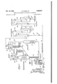
. the feed stock is introduced through line III by pump H to furnace l2 wherein the charge is vaporized and heated. As the heated vapor passes through transfer line l3 it picks up powdered catalyst from standpipe or catastat" M. The catalyst is introduced into the transfer line l3 in amounts regulated by slide valve or star feeder l5. It should be understood, of course, that steam or any other suitable means can be used for introducing the catalyst into transfer line I 3 and that the catalyst is carried by the vapors in this line to upflow reactor I6. If desired, the catalyst can be injected directly into the reactor IS instead of being introduced into the transfer line l3.
Reactor [6 can be a cylindrical vessel with a conical inlet and outlet respectively and of such size and cross-sectional area as to retain the necessary amount of catalyst for effecting the desired amount of conversion. The cross-sectional area should be such as to insure a vertical vapor velocity of between about 0.3 and 3 feet per second in the reactor if the reaction is to be effected under the desired fluid phase conditions. For example a reactor having an inside diameter of about 13 feet and a height of about 33 feet and a vapor velocity of about 1.2 feet per second to give a catalyst density of about 11 pounds per cubic foot of reactor space is satisfactory. It should be understood, however, that my invention is not limited to any particular reactor size and shape and that it is only necessary to provide a contact of the vapors with a sufiicient amount of catalyst to effect the desired conversion. Ve-
4 locities necessary to give a certain catalyst concentration will depend on catalyst size.
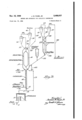
The reactor |8 can be provided with suitable means in heat transfer relation with the regenerator l1. For example internal coils l8 and I! or an external shell can be used through which can pass mercury, diphenyl, or molten salts, for example. The heat transfer medium picks up heat in the regenerator l1 and transfers the heat to reactor l6. Thus when fresh feed to the process is heat exchanged, it is brought to the approximate reaction temperature prevailing in reactor IB. If desired the reactor ll can be placed within the regenerator "as illustrated in Figure 2 of the drawings.
Reaction vapors carry catalyst from the top of the reactor It at the same rate at which catalyst is introduced into the reactor after a certain quantity of catalyst has accumulated in the reactor and equilibrium is reached in the upflow reactor. This catalyst-vapor stream is introduced by line 20 into cyclone separator 2| from the base of which spent catalyst falls through conduit 22 into stripper 23. An inert stripping gas such as steam is introduced through line 24 at the base of the stripping column 23. Reaction vapors leave cyclone separator 2| through line]! and these vapors, together with stripping gases from line 26, are introduced into cyclone separator 21 from which the remaining catalyst particles are returned to the stripper through conduit 28. The vapors from separator 21 are conveyed by line 29 to a fractionation system for separating a gasoline fraction from lighter and heavier reaction products. It should be understood that any other catalyst-vapor separation can be used instead of, or in conjunction with, the cyclone separators and that any number of cyclone separators can be used either in series or in parallel for effecting the separation.
The reaction vapors pass by line 29 to fractionator 30. Gasoline and gases are taken overhead through line 3| and cooler 32 to reflux drum 33. Gas can be vented from this receiver through line 38. A portion of the liquids can be recycled by valved line 35 and pump 36 as reflux in tower 30. The balance of the liquid is conducted by valved line 31 to stabilizer 38. Gas oil from fractionator 30 is withdrawn by valved line 39 and all or a portion recycled by pump 00 and line 4H to furnace l2. Likewise the recycle gas oil can be subjected to solvent extraction and the rafiinate recycled with fresh feed.
Stabilizer 38 is operated at an elevated pressure in the conventional manner. Reflux, pressure, and reboiling are controlled to take stabilized gasoline oil the base of tower 38 through valved line 44 for further treatment, storage, or use. Gases eliminated in producing stabilized gasoline pass overhead from stabilizer 38 to condenser 45 by line 46 and thence to reflux drum 1. Condensate is removed from drum 41 by means of valved line 48 and pump 49. A portion of it can be returned to stabilizer 38 as reflux through line 50 and the rest of the condensate can be withdrawn from the the desired product.
Reverting to stripper 23, the stripped spent catalyst is discharged into "downflow regenerator I! by lines 52 and/or 64. Catalyst can be recycled to reactor l6 by lines 62 and I3 as shown in Figure 2 of the drawing. Make-up catalyst can be introduced to the system as needed, for example by line 63. The expression "downflow" as herein employed refers to the flow of catalyst system by valved line 5| as from the regenerator and not to flow of gases therein.
In my downflow regenerator, air or other oxygen-containing gas can be introduced at the base of the regeneration zone within chamber I! through line 53. The regenerated catalyst is withdrawn from the bottom of the regeneration zone and the spent catalyst is introduced at a point above the gas inlet. Within this regeneration zone a catalyst residence time suflicient to rmit the combustion of carbonaceous materials is provided. The catalyst density in theregeneration zone can be. controlled by vapor velocity therein. I employ such gas velocities as will provide catalyst densities of about to 35 pounds per cubic foot, preferably between about and 30 pounds per cubic foot, for example pounds per cubic foot. Such gas velocities in this case can range between about 0.05 and 2.0 or more feet per second and are preferably between about 0.1 and 1.0 feet per second, all dependent upon catalyst size and particle density. For silicaalumina type catalysts I prefer to avoid temperatures in excess of 1050 F. to 1100 F. but the safe limit will, of course, depend upon the particular catalyst employed.
I provide for extraneous temperature control by using coils l8 or the like for circulating a heat exchange fluid such as fused salt mixture, mercury,'molten metal alloys, oil or steam. Likewise the reactor Hi can be constructed within the regenerator I! as shown in Figure 2.
Regenerated catalyst is withdrawn from the lower portion of the regeneration zone in chamber l1 and is accumulated below the regeneration zone and in standpipe l4. Catalyst is maintained in fluent condition by means of an inert gas such as steam introduced through lines 54 and Ma. The amount of aeration gases should be such as to maintain the catalyst in fluent form and of such density as to provide the necessary pressure head at the base of the standpipe. For obtaining densities of between about 20 and 30 pounds per cubic foot I employ gas velocities of between about 0.05 to 0.2 feet per second in the catalyst.
The regeneration gases carry some of the catalyst overhead by line 55 to cyclone separator 56 and the catalyst is returned to the top of regenerator I! by conduit 51. Additional catalyst can be removed by separator 59 and returned to regenerator IT by conduit 60. Vent gases are removed by line 6|.
The flow diagram of my process as well as the description thereof is highly simplified and various details such as heaters, coolers, pumps, valves, etc., have been omitted which would merely encumber this specification unnecessarily. While my invention has been described with reference to certain embodiments thereof, it is to be understood that they can be modified in various ways without departing from the invention and that I do not mean to be limited thereby but only by the appended claims.
I claim:
1. Apparatus for catalytic contacting whereina fluent catalyst is alternately onstream and regenerated comprising a vertical reaction chamber, means for accumulating catalyst from said reaction chamber, a vertical regeneration chamber, means for dispersing the accumulated catalyst in said regeneration chamber, a substantially vertical conduit of smaller cross-sectional area than said regeneration chamber communicating with the lower part of said regeneration chamber and adapted for accumulating a bodyof fluent catalyst whereby the pressure head at the base of said conduit is the sum of the pressure developed by the weight of the column of fluent catalyst in said conduit plus the pressure imposed at the top of said conduit by superimposed pressure in the regeneration chamber, means for introducing an inert fluidizing medium into said substantially vertical conduit at a relatively low point therein a valve below said lastnamed means, a transfer line leading to the base of said reaction chamber from a point below said valve and angularly disposed in respect to said conduit, and means whereby catalyst may be dispersed in amounts regulated by said valve from said conduit to said transfer line and thence back to the base of said reaction chamber.
2. A catalytic contacting apparatus which comprises a first contacting chamber, a second contacting chamber adapted to effect a net downward flow of fluent settled dense phase solid catalyst particles therefrom, downwardly extending conduitmeans communicating with the second contacting chamber-at a low point therein and adapted to accumulate a columnar body of settled catalyst particles therefrom, aerating means for introducing an inert aerating fluid into said conduit, a valve below the aerating means for regulating the flow of catalyst material in the conduit, means for transferring aerated catalyst from a point below the valve in said conduit to said first contacting chamber, means for supplying a different contacting fluid to each of said contacting chambers in volume suflicient to maintain a turbulent catalyst phase therein, means for withdrawing catalyst and contacting fluid from said first contacting chamber, means for separating the catalyst from said contacting fluid and means for introducing said catalyst into said second contacting chamber.
3. The method of operating a catalytic conversion system employing a powdered catalyst in conversion and regeneration zones which method comprises passing hydrocarbon vapors through a conversion zone in contact with a dense turbulent suspended powdered catalyst phase under such conditions as to effect catalytic conversion of said hydrocarbons, removing catalyst from reaction products, stripping deactivated catalyst with an inert gas and introducing said stripped catalyst into a regeneration zone, passing an oxygen-containing gas, upwardly in. said regeneration zone at such a vertical velocity as to maintain in the lower part of said zone a dense turbulent suspended powdered catalyst phase, withdrawing regeneration gases from the top of said regeneration zone, withdrawing regenerated catalyst as a downwardly moving column from a low point in the regeneration zone at which the catalyst density is at least about-10 pounds per cubic foot, introducing an aeration gas into the downwardly moving column for maintaining catalyst therein in fluent condition, suspending said catalyst from the base of said column at a controlled rate in a hydrocarbon stream and introducing said catalyst along with said stream back to said conversion zone.
4. The method of operating a catalytic conversion system employing a powdered catalyst in conversion and regeneration zones which method comprises passing hydrocarbon vapors through a conversion zone in contact with a dense, fluid ized turbulent suspended powdered catalyst phase under such conditions as to effect catalytic conversionof said hydrocarbons, removing catalyst from reaction products, stripping deactivated eans? catalyst with an inert gas and introducing sald stripped catalyst into a regeneration zone, passing an oxygen-containing gas upwardly in said regeneration zone at such a vertical velocity as to maintain in the lower part of said zone a dense, fluidized, turbulent suspended powdered catalyst phase, withdrawing regeneration gases from the top of said regeneration zone, withdrawing regenerated catalyst as a downwardly moving column from the dense, fluidized catalyst phase in the regeneration zone, introducing an aeration gas into the downwardly moving column for maintaining catalyst therein in fluent condition, suspending sald catalyst from the base of said column at a controlled rate in a hydrocarbon stream and introducing said catalyst along with said stream back to a low point in said conversion zone.
5. The method of contacting small particles of hard solids with three separate gaslform streams which method comprises dispersing said solids in a first gasiform stream, introducing said stream at the lower part of a first contacting zone l'and passing said stream upwardly in said zone at a sufliciently low velocity to maintain a dense suspended solids phase therein, separating solids from said first stream and-countercurrently contacting said separated solids with a second gasiform stream introducing said countercurrently contacted solids into a second contacting zone, introducing a third gasiform stream at the lower part of the second contacting zone and passing said third gasiform stream upwardly in said second contacting zone at a sufllciently low velocity to maintain a dense phase of suspended solids therein, removing said third gasiform stream from the upperpart of said secondcontacting zone while returning entrained solids from said stream to the dense suspended solids phase in the second contacting zone, downwardly withdrawing solids from the lower part of the second contacting zone as an aerated column of substantial height, introducing an aerating gas at a low point in the column in an amount suiflcient to maintain the column of solids in fluent form and of such density as to provide a pressure head at its base suflicient to effect the dispersion of solids from the base of the column into said first gasiform stream, and utilizing the pressure head at the base of said column for dispersing solids from said column into said first gasiform stream.
6. The method of effecting catalytic hydrocarbon conversion which comprises introducing a hydrocarbon stream into the lower part of a reaction zone containing hard, porous catalyst particles of about 400 to 150 mesh in particle size, passing said stream in gaseous form upwardly in said zone at a velocity within the approximate range of .3 to 3 feet per second whereby a. fluidized dense phase of catalyst is maintained in said zone, maintaining said zone at conversion temperature and pressure whereby hydrocarbon conversion is effected and carbonaceous material accumulates on the catalyst, separating catalyst from said hydrocarbon stream, stripping said separated catalyst with a stripping gas in astripping zone, combining gas from the stripping zone with said hydrocarbon stream, introducing stripped catalyst from the stripping zone into a regeneration zone, passing an oxygen-containing gas upwardly in the regeneration zone at a velocity within the range of about .1 to about 2 feet per second whereby a fluidized dense phase of catalyst is maintained in said zone, maintaining a temperature, pressure and catalyst residence time in the regeneration zone for effecting combustion of carbonaceous materials from the catalyst, separating and returning catalyst from gases leaving the upper part of the regeneration zone, downwardly withdrawing regenerated catalyst from the lower part of the regeneration zone as an aerated catalyst column of substantial length, introducing an aerating gas at a low point in said column in an amount to maintain the catalyst in fluent form and of such density as to provide a pressure head at the base of the column sufllcient to eifect transfer of the catalyst from the base of the column to the lower part of the reaction zone and transferring catalyst from the base of the column to the lower part of the reaction zone by introducing it into the hydrocarbon stream prior to the introduction of said stream into the reaction zone.
7. The method of claim 6 which includes the step of introducing stripped catalyst into the regeneration zone at an upper level therein.
8. In a continuous cyclic process for the catalytic conversion of hydrocarbons involving alternately and repeatedly contacting a powdered catalytic material with a vapor stream of the hydrocarbons in a catalytic conversion zone whereby carbonaceous deposits accumulate on the catalyst and thereafter contacting the used catalyst with an oxygen-containing gas in a regeneration zone to burn off the deposits, the steps including introducing particles of used catalytic material to the regeneration zone, flowing a stream of an oxygen-containing gas upwardly through the regeneration zone at a. velocity adapted to form a dense turbulent phase of the catalyst particles in said zone, adding used powdered catalyst to said dense phase and withdrawing corresponding amounts of regenerated catalyst therefrom at a rate adapted to maintain the average resident time of said particles within the regeneration zone at a suitable value, effecting said withdrawal of regenerated catalyst from the regeneration zone separate from the gaseous regeneration products through a catalyst withdrawal passageway opening directly at the lower portion of said dense phase, and continually introducing regenerated catalyst thus withdrawn under a pressure head, including that exerted by the dense phase of catalyst in the regeneration zone above the inlet to the catalyst withdrawal passageway, to said vapor stream of the hydrocarbons passing to the conversion zone.
9. The method of operating a catalytic conversion process employing hard catalyst particles which method comprises continuously introduc ing catalyst particles of about 150 to 400 mesh particle size into a vertical contacting zone, passing a gasiform stream upwardly through said contacting zone at such vertical velocity within the range of about 1 foot to about 2 feet per second as to maintain a bulk catalyst density in the lower part of said zone of at least about 10 pounds per cubic foot, continuously withdrawing a gasiform stream from the top of said contacting zone, separating catalyst particles from the withdrawn stream and returning the separated catalyst to the contacting zone, continuously removing cata lyst material as a downwardly moving column through the base of the vertical contacting zone from a point in the contacting zone at which the bulk density of the catalyst is within the range of approximately 10 to 35 pounds per cubic foot, introducing an aerating gas into said column in an amount sufilcient to maintain the catalyst in fluent form and of such density as to provide a pressure head at the base of the column sufficient to effect the introduction of said catalyst from the base of said column to a second contacting zone, passing catalyst from the base of said column to said second contacting zone and returning catalyst from said second contacting zone for reintroduction into the first-named vertical contacting zone.
10. The method of converting heavy hydrocarbons into gasoline which comprises dispersing small particles of a solid cracking catalyst consisting essentially of silica and at least one metal oxide in a gasiform stream consisting essentially of vapors of said heavy hydrocarbons at a cracking temperature, introducing said stream at the lower part of a cracking zone and passing said stream upwardly in said zone at a sufficiently low velocity to maintain a dense suspended catalyst phase therein, separating catalyst from said first stream, stripping said separated catalyst and introducing said stripped catalyst into a regeneration zone, introducing oxygen containing gas at the lower part of the regeneration zone and passing said oxygen containing gas upwardly in said regeneration zone at a sufliciently low velocity to maintain a dense phase of suspended catalyst therein, removing gases from the upper part of said regeneration zone while returning entrained catalyst from said gases to the dense suspended catalyst phase in the regeneration zone, downwardly withdrawing catalyst from the lower part of the regeneration zone as an aerated column of substantial height, introducing an aerating gas at a low point in the column in an amount suflicient to maintain the column of catalyst in fluent form and of such density as to provide a pressure head at its base sufficient to effect the dispersion of catalyst from the base of said column into the first-named stream, and utilizing the pressure head at the base of said column for dispersing catalyst from said column into said first-named stream.
11. The method of effecting catalytic cracking of heavy hydrocarbons for the production of gasoline which method comprises introducing a stream of hydrocarbons consisting essentially of gas oil into the lower part of a cracking zone containing hard porous particles, about 400 to 150 mesh in size, of a cracking catalyst consisting essentially of silica and at least one metal oxide,
- passing said stream in gaseous form upwardly in the cracking zone at a velocity within the approximate range of .3 to 3 feet per second whereby a fluidized dense phase of catalyst is maintained in said zone, maintaining said cracking zone at a temperature in the range 0! about 800 to 1000 F. under a pressure in the range of atmospheric to 50 pounds per square inch gauge whereby catalytic cracking is eflected and a carbonaceous malyst from the lower part of the regeneration zone as an aerated catalyst column of substantial length, introducing an aerating gas at a low point in said column in an amount to maintain the catalyst in fluent form and of such density as to provide a pressure head at the base of the column sumcient to efiect transfer of the catalyst from the based the column to the lower part of the cracking zone and transferring catalyst from the base of the column to the lower part of the cracking zone by introducing it into the hydrocarbon stream prior to the introduction of said stream into the cracking zone.
12. The method of contacting solids of small particle size with a plurality of gasiform streams which method comprises continuously introducing said solids into a first contacting zone, passing a first gasiform stream upwardly in said zone at a vertical velocity suillcient to maintain a mass of said solids in dense phase suspension therein, withdrawing said stream from the upper part of said zone, continuously withdrawing solids as a downwardly moving column directly from the dense phase in said zone, introducing sufllcient aeration gas into said column to maintain the solids therein in fluent form. dispersing solids from the base of said column into a second gasiform terial accumulates on the catalyst, separating catalyst from said hydrocarbon stream, stripping said separated catalyst with a stripping gas in a stripping zone, introducing stripped catalyst from the stripping zone into a regeneration zone, passstream, introducing-said second gasiform stream and the solids dispersed therein at the base of a second contacting zone, passing said second gasiform stream upwardly in said second contacting zone at a vertical velocity suflicient to maintain the solids in a-dense fluid phase therein, removing solids as a suspension in said second gasiform streamfrom said second contacting zone, separating solids fromthe withdrawn stream, introducing a third gasiform stream into the separated solids for displacing at least a part of the second gasiform stream therefrom, and thereafter returning said solids for said introduction to said first contacting zone.
JAMES M. PAGE. Jn.
sameness crran The following references are of record in the nle of this patent:
UNITED STATES PATENTS Number Name Date 1,475,502 Manning Nov. 27, 1923 1,577,534 Miller Mar. 23, 1926 1,984,380 Odell n-. Dec. 18, 1934 2,039,904 Hill May 5, 1'936 2,226,578 Payne Dec. 31, 1940 2,239,801 Voorhees Apr. 29, 1941 2,247,097 Menshih June 24, 1941 2,264,438 Gaylor Dec. 2, 1941 2,270J903 Rudback Jan. 27, 1942 2,273,075 Weems Feb. 17, 1942 2,302,209 Goddin Nov. 17, 1942 2,305,569 Degnen Dec. 15, 1942 2,325,136 Kassel July 27, 1943 2,326,705 Thiele et al. Aug. 10, 1943 2,327,175 Conn Aug. 17, 1943 2,331,433 Simpson et al. Oct. 12 1,943 2,340,878 Holt et al. Feb. 8, 1944 2,300,787 Murphree et al. Oct. 17, 1944 FOREIGN PATENTS Number Country Date 23,045 Great Britain 1910 331,322 Great Britain July 3, 1940 533,037 Germany Sept. 8, 1931
Priority Applications (1)
| Application Number | Priority Date | Filing Date | Title |
|---|---|---|---|
| US376763A US2488027A (en) | 1941-01-31 | 1941-01-31 | Method and apparatus for catalytic conversion |
Applications Claiming Priority (1)
| Application Number | Priority Date | Filing Date | Title |
|---|---|---|---|
| US376763A US2488027A (en) | 1941-01-31 | 1941-01-31 | Method and apparatus for catalytic conversion |
Publications (1)
| Publication Number | Publication Date |
|---|---|
| US2488027A true US2488027A (en) | 1949-11-15 |
Family
ID=23486379
Family Applications (1)
| Application Number | Title | Priority Date | Filing Date |
|---|---|---|---|
| US376763A Expired - Lifetime US2488027A (en) | 1941-01-31 | 1941-01-31 | Method and apparatus for catalytic conversion |
Country Status (1)
| Country | Link |
|---|---|
| US (1) | US2488027A (en) |
Cited By (12)
| Publication number | Priority date | Publication date | Assignee | Title |
|---|---|---|---|---|
| US2518693A (en) * | 1941-07-24 | 1950-08-15 | Standard Oil Dev Co | Process and apparatus for contacting finely divided solids and gases |
| US2562225A (en) * | 1941-07-31 | 1951-07-31 | Kellogg M W Co | Contacting gaseous materials with fluidized solids |
| US2642381A (en) * | 1949-08-27 | 1953-06-16 | Kellogg M W Co | Heat transfer between exothermic and endothermic reactions |
| DE1016873B (en) * | 1951-08-09 | 1957-10-03 | Kellogg M W Co | Chemical process for treating gases with solid materials |
| DE1028728B (en) * | 1954-12-31 | 1958-04-24 | Universal Oil Prod Co | Process for the transformation of petrol hydrocarbons |
| DE1029510B (en) * | 1954-12-31 | 1958-05-08 | Universal Oil Prod Co | Process for the transformation of petrol hydrocarbons |
| US3104957A (en) * | 1957-03-29 | 1963-09-24 | British Petroleum Co | Production of gas suitable for use as town gas |
| US3147208A (en) * | 1962-03-12 | 1964-09-01 | Sinclair Research Inc | Process for the hydrocracking of hydrocarbons with a cobalt-molybdenum on silica-alumina support type catalyst |
| US3261776A (en) * | 1962-05-23 | 1966-07-19 | Exxon Research Engineering Co | Conversion of hydrocarbons |
| US3353925A (en) * | 1962-05-23 | 1967-11-21 | Exxon Research Engineering Co | Apparatus for conversion of hydrocarbons |
| US3767566A (en) * | 1970-01-26 | 1973-10-23 | Standard Oil Co | Catalytic petroleum conversion process |
| US20060135358A1 (en) * | 2004-12-22 | 2006-06-22 | Lattner James R | Catalyst cooling processes utilizing steam superheating |
Citations (21)
| Publication number | Priority date | Publication date | Assignee | Title |
|---|---|---|---|---|
| GB191023045A (en) * | 1910-10-05 | 1911-08-24 | William Alfred Phillips | Improvements in Effecting Catalytic Reactions between Gases or Vapours. |
| US1475502A (en) * | 1922-06-16 | 1923-11-27 | Manning Refining Equipment Cor | Method of revivifying finely-divided fuller's earth, bone char, and the like |
| US1577534A (en) * | 1922-06-15 | 1926-03-23 | Silica Gel Corp | Method and apparatus for separating or recovering alpha gas from alpha mixture of gases |
| GB331322A (en) * | 1929-05-07 | 1930-07-03 | Eusebe Joseph Leonidas Francoi | Process for pneumatically transporting pulverulent material |
| DE533037C (en) * | 1928-01-12 | 1931-09-08 | Metallgesellschaft Ag | Process for the cycle coupling of two reactions between a solid powdery to small piece and a gaseous substance or mixture of substances |
| US1984380A (en) * | 1929-12-17 | 1934-12-18 | William W Odell | Process of producing chemical reactions |
| US2039904A (en) * | 1926-06-21 | 1936-05-05 | Gray Processes Corp | Refining of mineral oil distillates |
| US2226578A (en) * | 1939-06-14 | 1940-12-31 | Socony Vacuum Oil Co Inc | Kiln |
| US2239801A (en) * | 1938-01-08 | 1941-04-29 | Standard Oil Co | Catalytic cracking system |
| US2247097A (en) * | 1938-05-18 | 1941-06-24 | Standard Oil Dev Co | Catalytic cracking of hydrocarbon oil |
| US2264438A (en) * | 1938-12-29 | 1941-12-02 | Standard Oil Dev Co | Method for carrying out catalytic reactions |
| US2270903A (en) * | 1938-07-23 | 1942-01-27 | Bamag Meguin Ag | Method of treating gases with pulverulent substances |
| US2273075A (en) * | 1940-11-30 | 1942-02-17 | Standard Oil Co | Powdered catalyst system |
| US2302209A (en) * | 1940-12-16 | 1942-11-17 | Standard Oil Co | Catalytic conversion system |
| US2305569A (en) * | 1938-04-15 | 1942-12-15 | Kellogg M W Co | Process and apparatus for the catalytic conversion of hydrocarbon oil |
| US2325136A (en) * | 1939-01-23 | 1943-07-27 | Universal Oil Prod Co | Process for effecting catalyzed reactions |
| US2326705A (en) * | 1940-11-28 | 1943-08-10 | Standard Oil Co | Isoforming |
| US2327175A (en) * | 1941-10-31 | 1943-08-17 | Standard Oil Co | Catalyst control in hydrocarbon conversion |
| US2331433A (en) * | 1940-10-25 | 1943-10-12 | Socony Vacuum Oil Co Inc | Method and apparatus for catalytic conversion |
| US2340878A (en) * | 1939-12-23 | 1944-02-08 | Shell Dev | Method for executing vapor phase reactions |
| US2360787A (en) * | 1940-12-27 | 1944-10-17 | Standard Catalytic Co | Chemical process |
-
1941
- 1941-01-31 US US376763A patent/US2488027A/en not_active Expired - Lifetime
Patent Citations (21)
| Publication number | Priority date | Publication date | Assignee | Title |
|---|---|---|---|---|
| GB191023045A (en) * | 1910-10-05 | 1911-08-24 | William Alfred Phillips | Improvements in Effecting Catalytic Reactions between Gases or Vapours. |
| US1577534A (en) * | 1922-06-15 | 1926-03-23 | Silica Gel Corp | Method and apparatus for separating or recovering alpha gas from alpha mixture of gases |
| US1475502A (en) * | 1922-06-16 | 1923-11-27 | Manning Refining Equipment Cor | Method of revivifying finely-divided fuller's earth, bone char, and the like |
| US2039904A (en) * | 1926-06-21 | 1936-05-05 | Gray Processes Corp | Refining of mineral oil distillates |
| DE533037C (en) * | 1928-01-12 | 1931-09-08 | Metallgesellschaft Ag | Process for the cycle coupling of two reactions between a solid powdery to small piece and a gaseous substance or mixture of substances |
| GB331322A (en) * | 1929-05-07 | 1930-07-03 | Eusebe Joseph Leonidas Francoi | Process for pneumatically transporting pulverulent material |
| US1984380A (en) * | 1929-12-17 | 1934-12-18 | William W Odell | Process of producing chemical reactions |
| US2239801A (en) * | 1938-01-08 | 1941-04-29 | Standard Oil Co | Catalytic cracking system |
| US2305569A (en) * | 1938-04-15 | 1942-12-15 | Kellogg M W Co | Process and apparatus for the catalytic conversion of hydrocarbon oil |
| US2247097A (en) * | 1938-05-18 | 1941-06-24 | Standard Oil Dev Co | Catalytic cracking of hydrocarbon oil |
| US2270903A (en) * | 1938-07-23 | 1942-01-27 | Bamag Meguin Ag | Method of treating gases with pulverulent substances |
| US2264438A (en) * | 1938-12-29 | 1941-12-02 | Standard Oil Dev Co | Method for carrying out catalytic reactions |
| US2325136A (en) * | 1939-01-23 | 1943-07-27 | Universal Oil Prod Co | Process for effecting catalyzed reactions |
| US2226578A (en) * | 1939-06-14 | 1940-12-31 | Socony Vacuum Oil Co Inc | Kiln |
| US2340878A (en) * | 1939-12-23 | 1944-02-08 | Shell Dev | Method for executing vapor phase reactions |
| US2331433A (en) * | 1940-10-25 | 1943-10-12 | Socony Vacuum Oil Co Inc | Method and apparatus for catalytic conversion |
| US2326705A (en) * | 1940-11-28 | 1943-08-10 | Standard Oil Co | Isoforming |
| US2273075A (en) * | 1940-11-30 | 1942-02-17 | Standard Oil Co | Powdered catalyst system |
| US2302209A (en) * | 1940-12-16 | 1942-11-17 | Standard Oil Co | Catalytic conversion system |
| US2360787A (en) * | 1940-12-27 | 1944-10-17 | Standard Catalytic Co | Chemical process |
| US2327175A (en) * | 1941-10-31 | 1943-08-17 | Standard Oil Co | Catalyst control in hydrocarbon conversion |
Cited By (13)
| Publication number | Priority date | Publication date | Assignee | Title |
|---|---|---|---|---|
| US2518693A (en) * | 1941-07-24 | 1950-08-15 | Standard Oil Dev Co | Process and apparatus for contacting finely divided solids and gases |
| US2562225A (en) * | 1941-07-31 | 1951-07-31 | Kellogg M W Co | Contacting gaseous materials with fluidized solids |
| US2642381A (en) * | 1949-08-27 | 1953-06-16 | Kellogg M W Co | Heat transfer between exothermic and endothermic reactions |
| DE1016873B (en) * | 1951-08-09 | 1957-10-03 | Kellogg M W Co | Chemical process for treating gases with solid materials |
| DE1028728B (en) * | 1954-12-31 | 1958-04-24 | Universal Oil Prod Co | Process for the transformation of petrol hydrocarbons |
| DE1029510B (en) * | 1954-12-31 | 1958-05-08 | Universal Oil Prod Co | Process for the transformation of petrol hydrocarbons |
| US3104957A (en) * | 1957-03-29 | 1963-09-24 | British Petroleum Co | Production of gas suitable for use as town gas |
| US3147208A (en) * | 1962-03-12 | 1964-09-01 | Sinclair Research Inc | Process for the hydrocracking of hydrocarbons with a cobalt-molybdenum on silica-alumina support type catalyst |
| US3261776A (en) * | 1962-05-23 | 1966-07-19 | Exxon Research Engineering Co | Conversion of hydrocarbons |
| US3353925A (en) * | 1962-05-23 | 1967-11-21 | Exxon Research Engineering Co | Apparatus for conversion of hydrocarbons |
| US3767566A (en) * | 1970-01-26 | 1973-10-23 | Standard Oil Co | Catalytic petroleum conversion process |
| US20060135358A1 (en) * | 2004-12-22 | 2006-06-22 | Lattner James R | Catalyst cooling processes utilizing steam superheating |
| US7598197B2 (en) | 2004-12-22 | 2009-10-06 | Exxonmobil Chemical Patents Inc. | Catalyst cooling processes utilizing steam superheating |
Similar Documents
| Publication | Publication Date | Title |
|---|---|---|
| US3494858A (en) | Two-stage countercurrent catalyst regenerator | |
| US2440620A (en) | Contacting solids and gaseous fluids | |
| US2455419A (en) | Synthesis of hydrocarbons and regeneration of synthesis catalyst | |
| US2399050A (en) | Treating hydrocarbon fluids | |
| US2302209A (en) | Catalytic conversion system | |
| US2379408A (en) | Catalytic conversion system | |
| US2363874A (en) | Process and apparatus for treating fluids | |
| US2515156A (en) | Fluidized catalyst apparatus | |
| US2518693A (en) | Process and apparatus for contacting finely divided solids and gases | |
| US2400176A (en) | Catalytic conversion | |
| US2447505A (en) | Hydrocarbon synthesis with fluidized catalyst regeneration | |
| US2438728A (en) | Temperature control in fluidized catalyst systems | |
| US2488030A (en) | Fluidized catalytic conversion process | |
| US2488027A (en) | Method and apparatus for catalytic conversion | |
| US2697686A (en) | Method for effecting the conversion of fluid reactant streams by contact with a moving bed of solid particles | |
| US2431630A (en) | Method and apparatus for regeneration of catalyst | |
| US2488031A (en) | Catalytic conversion system | |
| US2425849A (en) | Powdered catalyst regeneration and recovery | |
| US2533666A (en) | Hydrocarbon synthesis | |
| US2758068A (en) | Process for utilizing the flue gas in the regeneration of the fouled catalyst in a fluidized hydrocarbon conversion system | |
| US2472427A (en) | Hydrocarbon synthesis with fluidized catalyst regeneration | |
| US2506307A (en) | Contacting gaseous fluids and solid particles | |
| US2428873A (en) | Process and apparatus for catalytic contacting | |
| US2585238A (en) | Method and apparatus for effecting the fluidized catalytic conversion of a reactant stream | |
| US4430201A (en) | Regeneration of fluidizable catalyst |