US2487620A - Desiccator - Google Patents
Desiccator Download PDFInfo
- Publication number
- US2487620A US2487620A US653217A US65321746A US2487620A US 2487620 A US2487620 A US 2487620A US 653217 A US653217 A US 653217A US 65321746 A US65321746 A US 65321746A US 2487620 A US2487620 A US 2487620A
- Authority
- US
- United States
- Prior art keywords
- stopper
- desiccant
- jar
- skirt
- disc
- Prior art date
- Legal status (The legal status is an assumption and is not a legal conclusion. Google has not performed a legal analysis and makes no representation as to the accuracy of the status listed.)
- Expired - Lifetime
Links
Images
Classifications
-
- B—PERFORMING OPERATIONS; TRANSPORTING
- B65—CONVEYING; PACKING; STORING; HANDLING THIN OR FILAMENTARY MATERIAL
- B65D—CONTAINERS FOR STORAGE OR TRANSPORT OF ARTICLES OR MATERIALS, e.g. BAGS, BARRELS, BOTTLES, BOXES, CANS, CARTONS, CRATES, DRUMS, JARS, TANKS, HOPPERS, FORWARDING CONTAINERS; ACCESSORIES, CLOSURES, OR FITTINGS THEREFOR; PACKAGING ELEMENTS; PACKAGES
- B65D51/00—Closures not otherwise provided for
- B65D51/24—Closures not otherwise provided for combined or co-operating with auxiliary devices for non-closing purposes
- B65D51/28—Closures not otherwise provided for combined or co-operating with auxiliary devices for non-closing purposes with auxiliary containers for additional articles or materials
- B65D51/30—Closures not otherwise provided for combined or co-operating with auxiliary devices for non-closing purposes with auxiliary containers for additional articles or materials for desiccators
-
- B—PERFORMING OPERATIONS; TRANSPORTING
- B01—PHYSICAL OR CHEMICAL PROCESSES OR APPARATUS IN GENERAL
- B01L—CHEMICAL OR PHYSICAL LABORATORY APPARATUS FOR GENERAL USE
- B01L1/00—Enclosures; Chambers
- B01L1/02—Air-pressure chambers; Air-locks therefor
-
- F—MECHANICAL ENGINEERING; LIGHTING; HEATING; WEAPONS; BLASTING
- F26—DRYING
- F26B—DRYING SOLID MATERIALS OR OBJECTS BY REMOVING LIQUID THEREFROM
- F26B21/00—Arrangements or duct systems, e.g. in combination with pallet boxes, for supplying and controlling air or gases for drying solid materials or objects
- F26B21/06—Controlling, e.g. regulating, parameters of gas supply
- F26B21/08—Humidity
- F26B21/083—Humidity by using sorbent or hygroscopic materials, e.g. chemical substances, molecular sieves
Definitions
- This invention relates to desiccators for food jars, containers for chemicals, etc., and has for its object to provide a novel and improved device of this type.
- Another object of the invention is to provide a simple and inexpensive desiccating stopper or cover which may be applied to existing types of jars, bottles and other containers to keep the contents dry, and is protected against absorption of outside moisture when removed from the container.
- Another object is to provide a self-contained desiccating stopper of the foregoing type which will display an indication of its own moisture content, and which, when saturated, may be revivified by the simple process of heating without dismantling or manual manipulation of any kind.
- my desiccating stopper comprises a cylindrical skirt portion which may be internally threaded for attachment to the threaded neck of a conventional food jar, and a transparent top or dome containing a hygroscopic material such as an indicating type of silica gel which has the property of changing its color according to the amount of moisture absorbed thereby.
- the desiccant such as the above mentioned silica gel is confined in the dome of the stopper by a screen, and access of air thereto is controlled by a valve assembly including a bimetallic disc which is automatically flexed to admit air to the dome when the stopper is secured on the jar, but seals the dome off from the outside atmosphere when the stopper is removed from the jar.
- a valve assembly including a bimetallic disc which is automatically flexed to admit air to the dome when the stopper is secured on the jar, but seals the dome off from the outside atmosphere when the stopper is removed from the jar.
- the desiccant will absorb moisture from the interior of the jar when the stopper is secured on the jar, but it will not absorb moisture from the outside atmosphere when off the ar.
- the stopper is simply removed from the jar and heated as by placing in an oven. The high temperature of the oven flexes the bimetallic disc and opens the dome of the stopper to the atmosphere of the oven, thus soon drying the desiccant and causing it to reacquire the distinctive color associated with such dry condition.
- thermo-sensitive bimetallic disc When the stopper is removed from the oven and cooled, the thermo-sensitive bimetallic disc reassumes its sealing position so that the desiccant will not be exposed to the atmosphere and will not reopen until the stopper is again secured on the jar as previously described.
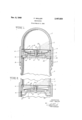
- Fig. l is a vertical sectional view of a desiccating stopper embodying the present invention, showing same secured on the neck of a conventional food jar;
- Fig. 2 is a broken sectional view of the stopper as it appears when removed from the jar.
- Fig. 1 shows a desiccator stopper comprising a transparent top or dome portion 5 and a cylindrical skirt portion 6 which is internally threaded at I to mate with the external threads 8 on the neck of a container such as a conventional Mason jar 9.
- the dome 5 of the stopper is integral with the skirt 6 and a circular internal ledge I0 is formed at their juncture.
- a fine mesh foraminous plate or screen I2 is clamped against the ledge [0 by a rigid spider 13 which, in turn, is secured in place by an annular channel-shaped valve seat I4 and a snap ring [5 sprung in an internal groove I6 in the skirt 6 of the stopper.
- the dome 5 of the stopper contains a hygroscopic material such as comminuted silica gel II which is confined therein by the screen l2.
- the material I! is preferably a well-known indicat- 3 ing type of silica gel which is pink when saturated with moisture and blue when dry. The color of the material is visible through the transparent dome 5 of the stopper.
- the valve mechanism for opening and closing the dome 5 of the stopper includes a flexible bimetallic disc iii, the properties of which are hereinafter more fully described, and a spring metal spider IS, the said members i3 and 19 being secured together and to the hub 28 of rigid spider l3 by a rivet 21 and spacers 22.
- the disc l3 spans the channeled area of the annular valve seat i and may either be raised ofi said valve seat to admit air to the dome 5 as shown in Fig. 1, or else seated on said valve seat to close the dome 5 oh from the outside air as shown in Fig. 2.
- the spring metal spider 19 has depending fingers 23 which extend outwardly beneath the snap ring is on the inner peripheral wall of skirt portion 6 of the stopper, so that said fingers 253; will engage outer annulus or pouring lip 24 of the jar 8 when the stopper is screwed down on the neck of the jar as shown in Fig. 1.
- the condition of the desiccant l! is alwaysievidentby itscolor which is visible through the transparent dome 5 or by its weight.
- the desiccant is blue its condition is: satisfactory. but "it changes toip'ink, this indicates that the material has absorbed its capacity of moisture and that it should be revivified.
- This is accomplished by removin the stopper from the jar and placing it in an oven.
- the bimetallic disc t8 which constitutes a thermostatic "valve engages the valve seat l 'l and sealsoii the dome 5, as previously described.
- the construction of the disc 18 is such that the high temperature of the oven flexes said disc to the position'shown in Fig.
- thermostatic valve may be replaced by a manually operated valve which is automatically opened or closed by contact with the jar as above described, but is opened manually for reactivation of the desiccant.
- a desiccating stopper for jars and other containers comprising a top containing a desiccant and a skirt for attachment to a container, a valve sealing the top of said stopper from said skirt and including thermo-sensitive means opening the valve automatically at elevated temperatures, and means in said stopper engageable with a cooperating container to open said valve.
- a desiccating stopper for jars and other containers comprising a top containing a desiccant and a skirt for attachment to a container, a
- thermo-sensitive means opening the valve automatically at elevated temperatures
- a desiccating stopper for jars and other containers comprising a transparent top for storing a desiccant and a skirtiior attachment to a container, a iorami-nous screen between said skirt and top for confining the desiccant in the latter, an indicating desiccant in said top having the property of changing its appearance when saturated with moisture, a valvesealing the top of said stop per from said skirt including thermo-sensitive means opening the valve when heated, and means in said stopper engageable with a cooperating container to open said valve.
- a desiccating stopper for jars and other con tainers comprising a transparent top for storing a desiccant and a skirt for attachment to a con-- tamer, a foram-inous screen between said skirt and top -ior confining the desiccant in the latter, an indicating desiccant in said top having the prop-- erty of changin its appearance when'saturated with moisture, a valve in said stopper includedin a valve seat and a flexible bimetallic thermo-sem sitive disc flexed to engage said valve seat to seal off the top of said stopper from said skirt, said disc being adapted upon: heating to flex out of engagement with said valve seat, and means in said stopper engageable with a cooperating container-for moving said disc ofisaid valve seat.
- Adesiccating-stopper for jars and other containers comprising a transparent top for storing a desiccant and askl-rt for attachment to a y container, a foraminous-screen between said skirt an annular *valve'sea-t and a flexible bimetallic disc flex-ed: to engage said. valve seat to seal off the top of said stopper troimsaid skirt, and means cooperating with said; disc and 'engageable. with the top. of a container to.
- saidbimetallic disc being adapted upon heating to flex out of engagement with said valve seat to admit drying air to the top oi said stopper.
- n 'desiccating stopper for jars and other containers comprising a'trarrspa'rent top for storing a desiccant and a cylindrical-skirt for attachment to. a container, 2. foraminousscreen between: said skirt and'top for confining the desiccant in the latter, an indicating desiccant in said top having the property of changing its color when saturated with-moisture, :a valve in said stopper including an annular valve seat and a flexible bimetallicdisc flexed to. engage said valve seat to seal off. the topqof said: stopper from said skirt,
- a desiccating stopper for said container comprising a transparent top for storing a desiccant and a cylindrical skirt for sealing attachment to said walls, a foraminous screen between said skirt and top for confining the desiccant in the latter, a desiccant in said top, a valve in said stopper including an annular valve seat and a. flexible disc flexed to engage said valve seat to seal ofi the top of said FRED WALLER.
Description
Patented Nov. 8, 1949 UNITED STATES PATENT OFFICE 7 Claims.
This invention relates to desiccators for food jars, containers for chemicals, etc., and has for its object to provide a novel and improved device of this type.
Another object of the invention is to provide a simple and inexpensive desiccating stopper or cover which may be applied to existing types of jars, bottles and other containers to keep the contents dry, and is protected against absorption of outside moisture when removed from the container.
Another object is to provide a self-contained desiccating stopper of the foregoing type which will display an indication of its own moisture content, and which, when saturated, may be revivified by the simple process of heating without dismantling or manual manipulation of any kind.
Various other objects and advantages will be apparent as the nature of the invention is more fully disclosed.
For purposes of illustration, I shall describe the invention as applied to a stopper for a conventional Mason jar containing a food product which it is desired to maintain in a dry state, although it will be evident as the description proceeds that it is equally applicable to a variety of other forms and uses.
In the specific embodiment disclosed herein, my desiccating stopper comprises a cylindrical skirt portion which may be internally threaded for attachment to the threaded neck of a conventional food jar, and a transparent top or dome containing a hygroscopic material such as an indicating type of silica gel which has the property of changing its color according to the amount of moisture absorbed thereby.
The desiccant such as the above mentioned silica gel is confined in the dome of the stopper by a screen, and access of air thereto is controlled by a valve assembly including a bimetallic disc which is automatically flexed to admit air to the dome when the stopper is secured on the jar, but seals the dome off from the outside atmosphere when the stopper is removed from the jar. As a result, the desiccant will absorb moisture from the interior of the jar when the stopper is secured on the jar, but it will not absorb moisture from the outside atmosphere when off the ar.
Whenever the desiccant has absorbed its full capacity of moisture from within the jar, this condition will be evident from the distinctive color of the desiccant which will show through the transparent dome of the stopper, or from the increased weight of the desiccant, indicating that the desiccant needs to be revivified. In order to reactivate the desiccant, the stopper is simply removed from the jar and heated as by placing in an oven. The high temperature of the oven flexes the bimetallic disc and opens the dome of the stopper to the atmosphere of the oven, thus soon drying the desiccant and causing it to reacquire the distinctive color associated with such dry condition. When the stopper is removed from the oven and cooled, the thermo-sensitive bimetallic disc reassumes its sealing position so that the desiccant will not be exposed to the atmosphere and will not reopen until the stopper is again secured on the jar as previously described.
Although the novel features which are characteristic of this invention are set forth more in detail in the claims appended hereto, the nature and scope of the invention may be better understood by referring to the following description, taken in connection with the accompanying drawing forming a part thereof, in which a specific embodiment has been set forth for purposes of illustration.
In the drawing:
Fig. l is a vertical sectional view of a desiccating stopper embodying the present invention, showing same secured on the neck of a conventional food jar; and
Fig. 2 is a broken sectional view of the stopper as it appears when removed from the jar.
In the following description certain specific terms are used for convenience in referring to the various details of the invention. These terms, however, are to be interpreted as broadly as the state of the art will permit.
In the drawing, Fig. 1 shows a desiccator stopper comprising a transparent top or dome portion 5 and a cylindrical skirt portion 6 which is internally threaded at I to mate with the external threads 8 on the neck of a container such as a conventional Mason jar 9.
In the embodiment illustrated, the dome 5 of the stopper is integral with the skirt 6 and a circular internal ledge I0 is formed at their juncture. A fine mesh foraminous plate or screen I2 is clamped against the ledge [0 by a rigid spider 13 which, in turn, is secured in place by an annular channel-shaped valve seat I4 and a snap ring [5 sprung in an internal groove I6 in the skirt 6 of the stopper.
The dome 5 of the stopper contains a hygroscopic material such as comminuted silica gel II which is confined therein by the screen l2. The material I! is preferably a well-known indicat- 3 ing type of silica gel which is pink when saturated with moisture and blue when dry. The color of the material is visible through the transparent dome 5 of the stopper.
The valve mechanism for opening and closing the dome 5 of the stopper includes a flexible bimetallic disc iii, the properties of which are hereinafter more fully described, and a spring metal spider IS, the said members i3 and 19 being secured together and to the hub 28 of rigid spider l3 by a rivet 21 and spacers 22. The disc l3 spans the channeled area of the annular valve seat i and may either be raised ofi said valve seat to admit air to the dome 5 as shown in Fig. 1, or else seated on said valve seat to close the dome 5 oh from the outside air as shown in Fig. 2.
The spring metal spider 19 has depending fingers 23 which extend outwardly beneath the snap ring is on the inner peripheral wall of skirt portion 6 of the stopper, so that said fingers 253; will engage outer annulus or pouring lip 24 of the jar 8 when the stopper is screwed down on the neck of the jar as shown in Fig. 1. When the stopper is thus secured on the neck of the jar 9 the depending fingers 23 of spider It) will be forced upwardly against the snap ring it; and the central arms of said spider l9 will engage the disc 18 and raise it off the valve seat It, thereby admitting air from the jar 9 to the dome 5 as indicated by the arrows in Fig. 1. It will thus be seen that the desiccant ii will attract and absorb moisture =fromthe'contents'of the jar 9 when the stopper is secured on the jar.
However, when the stopper is removed from the jar, asshown in Fig. 2, the spider fingers 23 will dropsdue to the spring fiexure of spider It, thus allowing the disc i8 to engage the valve seat i4 and -sealin the dome 5 off from the outside air This prevents the desiccant IT from absorbing moisture from the outside atmosphere when the stopper is off thejar.
In use, the condition of the desiccant l! is alwaysievidentby itscolor which is visible through the transparent dome 5 or by its weight. When the desiccant is blue its condition is: satisfactory. but "it changes toip'ink, this indicates that the material has absorbed its capacity of moisture and that it should be revivified. This is accomplished by removin the stopper from the jar and placing it in an oven. When the stopper is thus removed from the jar, the bimetallic disc t8 which constitutes a thermostatic "valve engages the valve seat l 'l and sealsoii the dome 5, as previously described. However, the construction of the disc 18 is such that the high temperature of the oven flexes said disc to the position'shown in Fig. 1, thereby-opening the dome 5 of thestopper to the atmosphere of the oven. The moisture is'thus'driven out of the desiccant l1 which'thereupon turns blue again. When the stopper is removed from the-oven and cooled, the disc is snaps down to its sealing position. as shown in Fig. 2,
and it will not reopen until the stopper is again secured'on the jar asshown in Fig. 1. Obviously, the thermostatic valve may be replaced by a manually operated valve which is automatically opened or closed by contact with the jar as above described, but is opened manually for reactivation of the desiccant.
Although a specific embodiment has been shown and described hereiny-for purposes of i1- lustration, it will be evident to those skilled in the art that the invention is capable of var'ous modifications and-adaptationswithin the scope of the appended claims.
What is claimed is:
l. A desiccating stopper for jars and other containers, comprising a top containing a desiccant and a skirt for attachment to a container, a valve sealing the top of said stopper from said skirt and including thermo-sensitive means opening the valve automatically at elevated temperatures, and means in said stopper engageable with a cooperating container to open said valve.
2. A desiccating stopper for jars and other containers, comprising a top containing a desiccant and a skirt for attachment to a container, a
-foraminous screen between said skirt and top for confining said desiccant in the latter, a valve sealing the top of said stopper from said skirt and including thermo-sensitive means opening the valve automatically at elevated temperatures, and means in said stopper engageable with a coope-rating container to open said valve.
3. A desiccating stopper for jars and other containers, comprising a transparent top for storing a desiccant and a skirtiior attachment to a container, a iorami-nous screen between said skirt and top for confining the desiccant in the latter, an indicating desiccant in said top having the property of changing its appearance when saturated with moisture, a valvesealing the top of said stop per from said skirt including thermo-sensitive means opening the valve when heated, and means in said stopper engageable with a cooperating container to open said valve.
4. A desiccating stopper for jars and other con tainers, comprising a transparent top for storing a desiccant and a skirt for attachment to a con-- tamer, a foram-inous screen between said skirt and top -ior confining the desiccant in the latter, an indicating desiccant in said top having the prop-- erty of changin its appearance when'saturated with moisture, a valve in said stopper includin a valve seat and a flexible bimetallic thermo-sem sitive disc flexed to engage said valve seat to seal off the top of said stopper from said skirt, said disc being adapted upon: heating to flex out of engagement with said valve seat, and means in said stopper engageable with a cooperating container-for moving said disc ofisaid valve seat.
-5. Adesiccating-stopper for jars and other containers, comprising a transparent top for storing a desiccant and askl-rt for attachment to a y container, a foraminous-screen between said skirt an annular *valve'sea-t and a flexible bimetallic disc flex-ed: to engage said. valve seat to seal off the top of said stopper troimsaid skirt, and means cooperating with said; disc and 'engageable. with the top. of a container to. move said disc cit said valve seat andt'her'eby-adm'it air tOfthQ top cf said stopper, saidbimetallic disc being adapted upon heating to flex out of engagement with said valve seat to admit drying air to the top oi said stopper.
6. n 'desiccating stopper for jars and other containers, comprising a'trarrspa'rent top for storing a desiccant and a cylindrical-skirt for attachment to. a container, 2. foraminousscreen between: said skirt and'top for confining the desiccant in the latter, an indicating desiccant in said top having the property of changing its color when saturated with-moisture, :a valve in said stopper including an annular valve seat and a flexible bimetallicdisc flexed to. engage said valve seat to seal off. the topqof said: stopper from said skirt,
and a flexible spider secured to said disc and having depending fingers positioned to engage the top of a cooperating container to flex said disc on said valve seat and thereby admit air to the desiccant in the top of said stopper, said bimetallio disc being adapted upon heating to flex in a direction to disengage said valve seat to admit drying air to the top of said stopper.
7. In a desiccator including a container having a wall defining a top opening, a desiccating stopper for said container, comprising a transparent top for storing a desiccant and a cylindrical skirt for sealing attachment to said walls, a foraminous screen between said skirt and top for confining the desiccant in the latter, a desiccant in said top, a valve in said stopper including an annular valve seat and a. flexible disc flexed to engage said valve seat to seal ofi the top of said FRED WALLER.
REFERENCES CITED The following references are of record in the file of this patent:
UNITED STATES PATENTS 15 Number Name Date 1,628,108 Brown May 10, 1927 2,315,049 Cronstedt Mar. 30, 1943
Priority Applications (1)
| Application Number | Priority Date | Filing Date | Title |
|---|---|---|---|
| US653217A US2487620A (en) | 1946-03-08 | 1946-03-08 | Desiccator |
Applications Claiming Priority (1)
| Application Number | Priority Date | Filing Date | Title |
|---|---|---|---|
| US653217A US2487620A (en) | 1946-03-08 | 1946-03-08 | Desiccator |
Publications (1)
| Publication Number | Publication Date |
|---|---|
| US2487620A true US2487620A (en) | 1949-11-08 |
Family
ID=24619962
Family Applications (1)
| Application Number | Title | Priority Date | Filing Date |
|---|---|---|---|
| US653217A Expired - Lifetime US2487620A (en) | 1946-03-08 | 1946-03-08 | Desiccator |
Country Status (1)
| Country | Link |
|---|---|
| US (1) | US2487620A (en) |
Cited By (12)
| Publication number | Priority date | Publication date | Assignee | Title |
|---|---|---|---|---|
| US2548168A (en) * | 1949-01-04 | 1951-04-10 | Luce Mfg Company | Food receptacle with desiccant |
| US2591055A (en) * | 1949-05-02 | 1952-04-01 | Harry W Dietert Company | Desiccator using an absorbent |
| US2845138A (en) * | 1955-12-27 | 1958-07-29 | Wells Ind Corp | Desiccator unit |
| US2915404A (en) * | 1955-05-12 | 1959-12-01 | Glidden Co | Lecithin package |
| US3085709A (en) * | 1961-11-14 | 1963-04-16 | 42 Products Ltd Inc | Bottle cap |
| US4146277A (en) * | 1978-06-29 | 1979-03-27 | Santoro Dario S | Desiccant cap |
| US4660760A (en) * | 1984-08-29 | 1987-04-28 | Spirax Sarco Limited | Thermodynamic steam trap valve discs |
| US4979400A (en) * | 1989-02-27 | 1990-12-25 | Proprietary Technology, Inc. | Force and elapsed time recording assembly |
| EP0415015A1 (en) * | 1989-09-01 | 1991-03-06 | Schütz-Dental Gmbh | Container for dental object |
| US6274304B1 (en) * | 1993-02-13 | 2001-08-14 | Roche Diagnostics Gmbh | Apparatus with desiccant chamber and method of using |
| FR2925662A1 (en) * | 2007-12-19 | 2009-06-26 | Millerail Sarl | Food product dewatering installation, has sealing device extending between circumference of base of cassette and edge of receptacle delimiting opening, where cassette has humidity absorption units |
| US8221705B2 (en) | 2007-06-21 | 2012-07-17 | Gen-Probe, Incorporated | Receptacles for storing substances in different physical states |
Citations (2)
| Publication number | Priority date | Publication date | Assignee | Title |
|---|---|---|---|---|
| US1628108A (en) * | 1927-05-10 | Display receptacle | ||
| US2315049A (en) * | 1940-08-22 | 1943-03-30 | United Aireraft Corp | Combined wire support and corrosion inhibitor |
-
1946
- 1946-03-08 US US653217A patent/US2487620A/en not_active Expired - Lifetime
Patent Citations (2)
| Publication number | Priority date | Publication date | Assignee | Title |
|---|---|---|---|---|
| US1628108A (en) * | 1927-05-10 | Display receptacle | ||
| US2315049A (en) * | 1940-08-22 | 1943-03-30 | United Aireraft Corp | Combined wire support and corrosion inhibitor |
Cited By (20)
| Publication number | Priority date | Publication date | Assignee | Title |
|---|---|---|---|---|
| US2548168A (en) * | 1949-01-04 | 1951-04-10 | Luce Mfg Company | Food receptacle with desiccant |
| US2591055A (en) * | 1949-05-02 | 1952-04-01 | Harry W Dietert Company | Desiccator using an absorbent |
| US2915404A (en) * | 1955-05-12 | 1959-12-01 | Glidden Co | Lecithin package |
| US2845138A (en) * | 1955-12-27 | 1958-07-29 | Wells Ind Corp | Desiccator unit |
| US3085709A (en) * | 1961-11-14 | 1963-04-16 | 42 Products Ltd Inc | Bottle cap |
| US4146277A (en) * | 1978-06-29 | 1979-03-27 | Santoro Dario S | Desiccant cap |
| US4660760A (en) * | 1984-08-29 | 1987-04-28 | Spirax Sarco Limited | Thermodynamic steam trap valve discs |
| US4979400A (en) * | 1989-02-27 | 1990-12-25 | Proprietary Technology, Inc. | Force and elapsed time recording assembly |
| EP0415015A1 (en) * | 1989-09-01 | 1991-03-06 | Schütz-Dental Gmbh | Container for dental object |
| US6274304B1 (en) * | 1993-02-13 | 2001-08-14 | Roche Diagnostics Gmbh | Apparatus with desiccant chamber and method of using |
| US10688458B2 (en) | 2007-06-21 | 2020-06-23 | Gen-Probe Incorporated | System and method of using multi-chambered receptacles |
| US11235295B2 (en) | 2007-06-21 | 2022-02-01 | Gen-Probe Incorporated | System and method of using multi-chambered receptacles |
| US11235294B2 (en) | 2007-06-21 | 2022-02-01 | Gen-Probe Incorporated | System and method of using multi-chambered receptacles |
| US10744469B2 (en) | 2007-06-21 | 2020-08-18 | Gen-Probe Incorporated | Multi-chambered receptacles |
| US8221705B2 (en) | 2007-06-21 | 2012-07-17 | Gen-Probe, Incorporated | Receptacles for storing substances in different physical states |
| FR2925662A1 (en) * | 2007-12-19 | 2009-06-26 | Millerail Sarl | Food product dewatering installation, has sealing device extending between circumference of base of cassette and edge of receptacle delimiting opening, where cassette has humidity absorption units |
| US8316556B2 (en) | 2007-12-19 | 2012-11-27 | Millerail | Zeolite dehydration unit |
| US20100263222A1 (en) * | 2007-12-19 | 2010-10-21 | Gilles Beurel | Zeolite dehydration unit |
| WO2009101302A3 (en) * | 2007-12-19 | 2009-10-15 | Millerail | Zeolite dehydration unit |
| WO2009101302A2 (en) * | 2007-12-19 | 2009-08-20 | Millerail | Zeolite dehydration unit |
Similar Documents
| Publication | Publication Date | Title |
|---|---|---|
| US2487620A (en) | Desiccator | |
| US2548168A (en) | Food receptacle with desiccant | |
| US2449014A (en) | Container closure | |
| US3010596A (en) | Closure seal for containers | |
| GB1499478A (en) | Container closures | |
| US2690946A (en) | Container with closure having desiccant holder | |
| US2797844A (en) | Adjustable diffuser devices | |
| US3892325A (en) | Child proof container closure | |
| US2492830A (en) | Dispensing container | |
| US2693864A (en) | Container for desiccant material and support therefor | |
| US3409160A (en) | Venting closure | |
| US4498608A (en) | Moisture absorbent condiment container | |
| US3115981A (en) | Closure assembly for vacuum bottles | |
| US3313440A (en) | Container closure | |
| NZ218120A (en) | Vented container closure | |
| US4341316A (en) | Insulating vessel | |
| ES457905A1 (en) | Air tight wine cooler container and dispenser - has adjustable lid kept in contact with surface by screw mechanism | |
| JPH019457Y2 (en) | ||
| CN210474021U (en) | Reagent bottle | |
| US1947382A (en) | Can, box, canister, and the like | |
| US3421648A (en) | Storage assembly for home food processing closure | |
| CN208593657U (en) | A kind of damp proof moisture-proof tea can | |
| KR940008442B1 (en) | Lunch box | |
| US2765945A (en) | Expandable stoppers | |
| CN207640136U (en) | A kind of electric cooker pot cover easy to install |