US2486069A - Envelope feeding mechanism with slidably and pivotally mounted gripper arms - Google Patents
Envelope feeding mechanism with slidably and pivotally mounted gripper arms Download PDFInfo
- Publication number
- US2486069A US2486069A US2068A US206848A US2486069A US 2486069 A US2486069 A US 2486069A US 2068 A US2068 A US 2068A US 206848 A US206848 A US 206848A US 2486069 A US2486069 A US 2486069A
- Authority
- US
- United States
- Prior art keywords
- spindle
- envelope
- cam
- arms
- envelopes
- Prior art date
- Legal status (The legal status is an assumption and is not a legal conclusion. Google has not performed a legal analysis and makes no representation as to the accuracy of the status listed.)
- Expired - Lifetime
Links
- NJPPVKZQTLUDBO-UHFFFAOYSA-N novaluron Chemical compound C1=C(Cl)C(OC(F)(F)C(OC(F)(F)F)F)=CC=C1NC(=O)NC(=O)C1=C(F)C=CC=C1F NJPPVKZQTLUDBO-UHFFFAOYSA-N 0.000 description 3
- 230000000694 effects Effects 0.000 description 2
- 239000002783 friction material Substances 0.000 description 2
- 239000000463 material Substances 0.000 description 2
- 239000002184 metal Substances 0.000 description 2
- 230000003534 oscillatory effect Effects 0.000 description 2
- 101100082060 Xenopus laevis pou5f1.1 gene Proteins 0.000 description 1
- 229910052738 indium Inorganic materials 0.000 description 1
- 238000005303 weighing Methods 0.000 description 1
Images


Classifications
-
- B—PERFORMING OPERATIONS; TRANSPORTING
- B65—CONVEYING; PACKING; STORING; HANDLING THIN OR FILAMENTARY MATERIAL
- B65B—MACHINES, APPARATUS OR DEVICES FOR, OR METHODS OF, PACKAGING ARTICLES OR MATERIALS; UNPACKING
- B65B43/00—Forming, feeding, opening or setting-up containers or receptacles in association with packaging
- B65B43/42—Feeding or positioning bags, boxes, or cartons in the distended, opened, or set-up state; Feeding preformed rigid containers, e.g. tins, capsules, glass tubes, glasses, to the packaging position; Locating containers or receptacles at the filling position; Supporting containers or receptacles during the filling operation
- B65B43/50—Feeding or positioning bags, boxes, or cartons in the distended, opened, or set-up state; Feeding preformed rigid containers, e.g. tins, capsules, glass tubes, glasses, to the packaging position; Locating containers or receptacles at the filling position; Supporting containers or receptacles during the filling operation using rotary tables or turrets
Definitions
- This invention relates to automatic machines of the kind employed for inserting weighed or measured quantities of seeds, or granular, powdered or like materials into small paper bags or envelopes hereinafter generically termed envelopes.
- the primary object of the invention is to provide an improved mechanism for transferring the envelopes individually from a receptacle to a rotary work table.
- a further object of the invention is to provide improved means for attaching and releasing the envelopes to and from the work table.
- the invention comprises the combination with a rotary work table and an envelope receptacle, of a vertical spindle, a pair of gripper arms carried by the spindle and adapted to transfer envelopes individually from the receptacle to the table, one of the arms being secured to the spindle and the other being connected to the spindie by a torsion spring, a hollow actuating spindie surrounding a portion of the gripper-arm spindle, the hollow spindle being adapted to impart angular movements to the arms and to permit a small amount of relative angular movement between the arms, a friction device acting on the gripper-arm spindle, means for oscillating the hollow spindle, and means for imparting vertical movements to the spindles.
- the invention comprises the combination with the rotary work table, of a plurality of envelope clips situated at the positions at which the envelopes are to be attached, and a cam for actuating the clips.
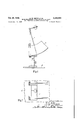
- Figures 1 and 2 are side elevations taken at right angles to each other of the upper part, Figures 3 and 4 corresponding side elevations of the lower part, and Figure 5 a part sectional plan, of an automatic machine constructed in accordance with the invention.
- Figures 6 and 7 are respectively a side elevation and a plan of the envelope receptacle.
- Figures 8 and 9 are respectively a sectional side elevation and a sectional plan, drawn to a larger scale than Figures 1 to '7, of the means employed for transferring the envelopes from the receptacle to the work table, Figure 9 being taken on the line 9-9 of Figure 8.
- the periphery of the table a is provided with four shallow pockets b situated at apart and each adapted to receive an envelope. These pockets may be made from sheet metal and secured to the periphery of the table, or they may have the form of recesses in the table periphery, but in either case the pockets have diverging side walls.
- the table a is rotatably supported on the upper end of a hollow pedestal c which at its lower end is secured to a fixed horizontal plate cZ.
- Unidirectional angular movements are imparted intermittently to the table a by any convenient means which in the example shown comprise an oscillatory cam e arranged in a central recess in the upper surface of the table, and pawls j slidably mounted in radial recesses formed in the upper surface of the table around the central recess, the pawls being loaded by springs g which serve to retain the inner ends of the pawls in contact with the cam periphery, and being al ternately engageable by a shoulder h on the cam during successive movements of the cam in one direction.
- a cover piece 2' secured on the upper surface of the table a serves to enclose the open upper sides of the recesses containing the cam e and pawls ,f.
- the cam e is secured on the upper end of a vertical operating spindle i which passes through a central hole in the table a and through the hollow pedestal c, the lower end of this spindle being connected to a driving spindie is through crank mechanism m and bevel gearing n, the arrangement being such that rotary motion of the driving spindle causes the camoperating spindle to be oscillated through an angle of slightly more than 90. Motion is imparted to the driving spindle R from any convenient source, such as an electric motor (not shown).
- a trough-like receptacle 0 of segmental shape adapted to hold a stack of envelopes 17, each envelope in the stack being arranged with its mouth upper-most and with its flap extending from the mouth.
- a narrow ledge q is formed or secured at each of the two vertical edges of the receptacle to hold the envelopes p in position, and the stack of envelopes are pressed forward towards this end by a weighted lever racting on the rear of the stack.
- a vertical 3 and axially slidable spindle s At a position adjacent to the space between the table a and the receptacle o is arranged a vertical 3 and axially slidable spindle s. Near the lower end of this spindle s is secured a collar t having a flat under-face, and beneath this collar is freely mounted on the spindle another (and non-rotatable) collar 11, having a fiat upper face. Between and in contact with the adjacent fiat faces of the collars t, u is arranged a disc 12 of friction material. The lower collar u is pressed towards the upper collar by an adjustable spring 10 mounted on the lower end of the spindle s, and is engaged with one end of an operating lever a: through the medium of a pair of diametrically opposite pivots y.
- the purpose of the lever a is to impart vertical (up and down) movements to the spindle s, the latter being actuated at appropriate times in the successive cycles of operation by asuitably shaped cam 2.
- the lever a is freely mounted on a horizontal shaft 2, the latter being supported by bearings as 3 on a horizontal plate d below the above mentioned plated.
- cam-shaft t Arranged adjacent to and parallel with the shaft 2 is cam-shaft t on which the cam 2 is secured, the cam-shaft being journalled in bearings as 5 on the plate d
- the lever 11 is to impart vertical (up and down) movements to the spindle s, the latter being actuated at appropriate times in the successive cycles of operation by asuitably shaped cam 2.
- the lever a is freely mounted on a horizontal shaft 2, the latter being supported by bearings as 3 on a horizontal plate d below the above mentioned plated.
- cam-shaft t Arranged adjacent to and parallel with the shaft 2 is cam-shaft t on which the cam
- a pair of laterally extending gripper arms in, M which terminate at their outer ends in depending fingers l2, l3.
- the finger l2 has a thin lower end adapted to enter easily into the open mouth of an envelope 1) in the receptacle 0,
- the arm ll carrying the finger I3 is secured to the spindle s.
- the other arm id is connected to the spindle s through anadjustable torsion spring I5 which surrounds the upper end of the spindle and tends to move the fingers i2, i3 apart, one end of this spring being anchored to the arm 10, and the other end being anchored to a short sleeve I5 which is adjustably secured on the upper end of the spindle s by a set-screw I5 Surrounding the portion of the spindle s between the arms it, it and the upper collar t, is mounted a hollow actuating spindle l6.
- the hollow spindle It has formed on or secured to it a stirrup-like part i! which embraces the adjacent ends of both arms In, H.
- the arms is, l l extend through an opening [8 in one side of the stirrup-like part I], and the width of this opening is made such as will allow sufficient relative angular movements between the arms to allow the fingers i2, it to separate to the required extent.
- a laterally extending arm i9 which is connected by a link 25 to an operating lever 2
- is adapted to be actuated at appropriate intervals by a suitably shaped cam 22 on the cam-shaft 4, and for this purpose carries a roller 23 which bears on the periphery of the cam under the action of a spring 2 secured to the lever.
- the lower end of "the hollow spindle 16 may rest on the upper side of the upper collar t abovementioned, and both spindles s and it are supported in part by the above-mentioned pivots y and by a fixed guide bearing 25 embracing the upper part of the hollow spindle It.
- the gripper end of the spindle s are arms H], II are first swung to a position such that the finger I2 lies over the open end of the envelope p which is adjacent to the delivery end of the envelope receptacle 0.
- the arms III, II are then lowered by downward movement of the spindles 3, I6 so as to cause the thin finger l2 to enter the envelope.
- a return movement is [given to the hollow spindle IS.
- the first effect of this movement is to cause the spring controlled arm IE to be moved towards the other H (which is temporarily held by the friction between the two collars t, u) and so cause the front side of the envelope to be gripped between the fingers 12, :13.
- these clips may have any convenient form, and in the example shown consist of hook-like projections on the outer ends of the spring-loaded pawls i above mentioned, the associated cam 6 bein adapted to impart outward movements to the clips through the pawls against the action of the springs g associated with the pawls.
- the shoiilder h on the cam serves by engaging the pawl f associated with the envelope-engaging clip '26 to move th table 'to the position in which the enve'lope can be fully opened by a vertically movable spreader.
- This latter comprises a pair of arms 23 depending from and respectively secured their upper ends to a pair of short horizontal pivot spindles 2-9, the latter being journalled in a bearing 30 on the upper end of a vertical and axially slidable spindle '31 which passes through the plate (1 above mentioned, and is supported by the fixed guide bearing 25.
- the *lower end of the spindle 34 is connected by a link 32 'to one end of a lever 33 which at its other end is freely mounted on the horizontal shaft 2, and which is operable at ap--litiste intervals by a cam 34 on th cam-shaft 4 to cause vertical movement of the spindle, the lever carrying a roller 35 which rests on the periphery of the cam.
- a pair of short levers 36 which are interconnected by a tension spring 3?.
- the next forward movement of the cam e serves to move the table a into the position in which the envelope is situated above a table or conveyor as 40, and during its ensuing return movement the cam imparts outward movement to the pawl J carrying the envelope-engaging clip 26, thus releasing the envelope and allowing it to fall between a pair of guides 4
- envelopes are successively transferred from the receptacle 0 and passed through the four stages above described, and that whilst one envelope is passing through one stage others are passing through the other stages.
- the machine above described is suitable for charging envelopes of diiferent sizes.
- An automatic machine of the kind specified comprising the combination with a rotary work table and an envelope receptacle, of a'vertical spindle, a pair of gripper arms carried by the spindle and adapted to transfer envelopes individually from the receptacle to the table, one of the arms being secured to the spindle, a torsion spring connecting the other arm to the spindle, a hollow actuating spindle surrounding a portion of the gripper-arm spindle, the hollow spindle being adapted to impart angular movements to the arms and to permit a small amount of relative angular movement between the arms, a friction device acting on the gripper-arm spindle for temporarily holding the arm secured thereto against angular movement with the hollow spindle, to permit the said relative movement between the arms, means for oscillating the hollow spindle, and means for imparting vertical movements to the spindles.
- An automatic machine as claimed in claim 1 having in combination a vertically movable spreader adapted to enter and open the envelopes transferred to the table, and an adjustable abutment for actuating the spreader.
Description
Oct. 25, 1949. A. R. SMITH ET AL ENVELOPE FEEDING MECHANISM WITH SLIDABLY AND PIVOTALLY MOUNTED GRIPPER ARMS Filed Jan. 13, 1948 6 Sheets-Sheet 1 Oct. 25, 1949 A. R. SMITH ET AL 2,486,069
ENVELOPE FEEDING MECHANISM WITH SLIDABLY AND PIVOTALLY MOUNTED GRIPPER ARMS Filed Jan. 13, 1948 6 Sheets-Sheet 2 Oct 25, 1949, A. R SMITH ET AL 2,486,069
ENVELOPE FEEDING MECHANISM WTH QQLIDABLY AND PIVO'I'ALLY MOUNTED GRIPPER ARMS Filed Jan. 13 1948 6 Sheets-Sheet 3 4, L211! 631273035 d L t? 6 .4. J1 61m Z blb C .flo vl 03:5
0 a M rdtigks Oct. 25, 1949. A. R. SMITH ET AL ENVELOPE FEEDING MECHANISM WITH SLIDABLY AND PIVOTALLY MOUNTED GRIPPER ARMS 6 Sheets-Sheet 4 Filed Jan. 15, 1948 6 Sheets-Sheet 5 Filed Jan. 13, 1948 @miah c, J. 1550 pi WM fla Fig.7
Oct. 25, 1949. A. R. SMITH ET AL 2,486,069
ENVELOPE FEEDING MECHANISM WITH SLIDABLY AND PIVOTALLY MOUNTED GRIPPER ARMS 6 Sheets-Sheet 6 Filed Jan. 13, 1948 Patented Oct. 25, 1949 ENVELOPE FEEDING MECHANISM WITH SLIDABLY AND PIVOTALLY MOUNTED GRIPPER ARMS Arthur Ronald Smith, Birmingham, and George Arthur Lee 'and Cyril J. Hopkins, Cuffley, England Application January 13, 1948, Serial No. 2,068 In Great Britain December 30, 1942 Section 1, Public Law 690, August 8, 1946 Patent expires December 30, 1962 6 Claims.
This invention relates to automatic machines of the kind employed for inserting weighed or measured quantities of seeds, or granular, powdered or like materials into small paper bags or envelopes hereinafter generically termed envelopes. I
The primary object of the invention is to provide an improved mechanism for transferring the envelopes individually from a receptacle to a rotary work table. A further object of the invention is to provide improved means for attaching and releasing the envelopes to and from the work table.
The invention comprises the combination with a rotary work table and an envelope receptacle, of a vertical spindle, a pair of gripper arms carried by the spindle and adapted to transfer envelopes individually from the receptacle to the table, one of the arms being secured to the spindle and the other being connected to the spindie by a torsion spring, a hollow actuating spindie surrounding a portion of the gripper-arm spindle, the hollow spindle being adapted to impart angular movements to the arms and to permit a small amount of relative angular movement between the arms, a friction device acting on the gripper-arm spindle, means for oscillating the hollow spindle, and means for imparting vertical movements to the spindles.
Also the invention comprises the combination with the rotary work table, of a plurality of envelope clips situated at the positions at which the envelopes are to be attached, and a cam for actuating the clips.
In the accompanying sheets of explanatory drawings:
Figures 1 and 2 are side elevations taken at right angles to each other of the upper part, Figures 3 and 4 corresponding side elevations of the lower part, and Figure 5 a part sectional plan, of an automatic machine constructed in accordance with the invention.
Figures 6 and 7 are respectively a side elevation and a plan of the envelope receptacle.
Figures 8 and 9 are respectively a sectional side elevation and a sectional plan, drawn to a larger scale than Figures 1 to '7, of the means employed for transferring the envelopes from the receptacle to the work table, Figure 9 being taken on the line 9-9 of Figure 8.
In carrying the invention into effect as shown, we employ a rotary table a adapted to carry an envelope through four stages, these stages being such that an envelope is attached to the table at the first, is fully opened at the second, is
2 charged at the third, and released at the fourth, in the manner hereinafter described. The periphery of the table a is provided with four shallow pockets b situated at apart and each adapted to receive an envelope. These pockets may be made from sheet metal and secured to the periphery of the table, or they may have the form of recesses in the table periphery, but in either case the pockets have diverging side walls. The table a is rotatably supported on the upper end of a hollow pedestal c which at its lower end is secured to a fixed horizontal plate cZ. Unidirectional angular movements are imparted intermittently to the table a by any convenient means which in the example shown comprise an oscillatory cam e arranged in a central recess in the upper surface of the table, and pawls j slidably mounted in radial recesses formed in the upper surface of the table around the central recess, the pawls being loaded by springs g which serve to retain the inner ends of the pawls in contact with the cam periphery, and being al ternately engageable by a shoulder h on the cam during successive movements of the cam in one direction. A cover piece 2' secured on the upper surface of the table a serves to enclose the open upper sides of the recesses containing the cam e and pawls ,f. The cam e is secured on the upper end of a vertical operating spindle i which passes through a central hole in the table a and through the hollow pedestal c, the lower end of this spindle being connected to a driving spindie is through crank mechanism m and bevel gearing n, the arrangement being such that rotary motion of the driving spindle causes the camoperating spindle to be oscillated through an angle of slightly more than 90. Motion is imparted to the driving spindle R from any convenient source, such as an electric motor (not shown).
Alongside and at a position below the level of the table a there is adjustably mounted on the plate (1 a trough-like receptacle 0 of segmental shape adapted to hold a stack of envelopes 17, each envelope in the stack being arranged with its mouth upper-most and with its flap extending from the mouth. At the front and open end of the receptacle 0 a narrow ledge q is formed or secured at each of the two vertical edges of the receptacle to hold the envelopes p in position, and the stack of envelopes are pressed forward towards this end by a weighted lever racting on the rear of the stack.
At a position adjacent to the space between the table a and the receptacle o is arranged a vertical 3 and axially slidable spindle s. Near the lower end of this spindle s is secured a collar t having a flat under-face, and beneath this collar is freely mounted on the spindle another (and non-rotatable) collar 11, having a fiat upper face. Between and in contact with the adjacent fiat faces of the collars t, u is arranged a disc 12 of friction material. The lower collar u is pressed towards the upper collar by an adjustable spring 10 mounted on the lower end of the spindle s, and is engaged with one end of an operating lever a: through the medium of a pair of diametrically opposite pivots y. The purpose of the lever a: is to impart vertical (up and down) movements to the spindle s, the latter being actuated at appropriate times in the successive cycles of operation by asuitably shaped cam 2. At the end remote from the pivots y the lever a: is freely mounted on a horizontal shaft 2, the latter being supported by bearings as 3 on a horizontal plate d below the above mentioned plated. Arranged adjacent to and parallel with the shaft 2 is cam-shaft t on which the cam 2 is secured, the cam-shaft being journalled in bearings as 5 on the plate d The lever 11:
carries a roller 5 which bears on the periphery of the cam 2 under the action of a spring '5. Motion is imparted to the cam-shaft ll from the driving spindle 7c through the medium of chain-andsprocket mechanism 8 and bevel gearing 9.
Near the upper arranged a pair of laterally extending gripper arms in, M which terminate at their outer ends in depending fingers l2, l3. The finger l2 has a thin lower end adapted to enter easily into the open mouth of an envelope 1) in the receptacle 0,
and on the lower end of the other finger I3 is provided a soft rubber or other pad [4. The arm ll carrying the finger I3 is secured to the spindle s. The other arm id is connected to the spindle s through anadjustable torsion spring I5 which surrounds the upper end of the spindle and tends to move the fingers i2, i3 apart, one end of this spring being anchored to the arm 10, and the other end being anchored to a short sleeve I5 which is adjustably secured on the upper end of the spindle s by a set-screw I5 Surrounding the portion of the spindle s between the arms it, it and the upper collar t, is mounted a hollow actuating spindle l6. At its upper end the hollow spindle It has formed on or secured to it a stirrup-like part i! which embraces the adjacent ends of both arms In, H. The arms is, l l extend through an opening [8 in one side of the stirrup-like part I], and the width of this opening is made such as will allow sufficient relative angular movements between the arms to allow the fingers i2, it to separate to the required extent. To the hollow spindle H5 is secured a laterally extending arm i9 which is connected by a link 25 to an operating lever 2| freely mounted on the shaft 2. The lever 2| is adapted to be actuated at appropriate intervals by a suitably shaped cam 22 on the cam-shaft 4, and for this purpose carries a roller 23 which bears on the periphery of the cam under the action of a spring 2 secured to the lever.
The lower end of "the hollow spindle 16 may rest on the upper side of the upper collar t abovementioned, and both spindles s and it are supported in part by the above-mentioned pivots y and by a fixed guide bearing 25 embracing the upper part of the hollow spindle It.
The action of the mechanism so far described is as follows:
By means of the hollow spindle Hi the gripper end of the spindle s are arms H], II are first swung to a position such that the finger I2 lies over the open end of the envelope p which is adjacent to the delivery end of the envelope receptacle 0. The arms III, II are then lowered by downward movement of the spindles 3, I6 so as to cause the thin finger l2 to enter the envelope. Then a return movement is [given to the hollow spindle IS. The first effect of this movement is to cause the spring controlled arm IE to be moved towards the other H (which is temporarily held by the friction between the two collars t, u) and so cause the front side of the envelope to be gripped between the fingers 12, :13. Continued movement of the arms Ml, H causes'the envelope p to be withdrawn from the receptacle .0 and transferred to the adjacent pocket 1) of the table a. Finally an upward movement is given to the spindles s, [6, but as the front side of the envelope p carried by the fingers l2, I3 is now arrested by one of a plurality of clips '2-$-on the table a-the efiect of this movement is to .cause the fingers l2, 13 to be carried clear of the envelope.
At the beginning of the next swing oi the arms Ill, H, the friction between the collars t, u temporarily retards the arm I i secured to the inner spindle s and allows the other arm Hi to move under its spring action vfor separating the fingers i2, it in readiness for engagement with the next envelope.
As regards the clips 28 for securing the envelopes to the table at, one such 01113215 provided at the inner end of each of the pockets 1). These clips may have any convenient form, and in the example shown consist of hook-like projections on the outer ends of the spring-loaded pawls i above mentioned, the associated cam 6 bein adapted to impart outward movements to the clips through the pawls against the action of the springs g associated with the pawls. When an envelope is transferred by the gripper arms ill, H to a pocket b in the vtable a, the upper edge of the front portion of theenvelope is:brought under the corresponding clip 2:8, and then immediately clamped by the clip against :the inner end of the pocket as a consequenc of the ensuing angular movement of the cam e relatively to the table a, this movement of the cam being in the direction opposite to that required for imparting movementto the table, and being hereinafter referred to as the return movement of the cam. To ensur that such movement of the cam e has no eftecton the position of the table a, any convenient friction material may be arranged between the underside of the table and the upper end of the pedestal c. When the envelope is engaged by the clip, the fingers i t, it are withdrawn from the envelope, and the mouthof the envelope is opened by compressed air from a nozzle 21.
During the next movement-of thecam e in the forward direction, that isto say the direction for moving the table a, =the shoiilder h on the cam serves by engaging the pawl f associated with the envelope-engaging clip '26 to move th table 'to the position in which the enve'lope can be fully opened by a vertically movable spreader. This latter comprises a pair of arms 23 depending from and respectively secured their upper ends to a pair of short horizontal pivot spindles 2-9, the latter being journalled in a bearing 30 on the upper end of a vertical and axially slidable spindle '31 which passes through the plate (1 above mentioned, and is supported by the fixed guide bearing 25. The *lower end of the spindle 34 is connected by a link 32 'to one end of a lever 33 which at its other end is freely mounted on the horizontal shaft 2, and which is operable at ap-- propriate intervals by a cam 34 on th cam-shaft 4 to cause vertical movement of the spindle, the lever carrying a roller 35 which rests on the periphery of the cam. Also depending from and respectively secured at their upper ends to the pivot spindles 29 are a pair of short levers 36 which are interconnected by a tension spring 3?. When the vertical spindle 3! is in its upper position the spring 3'! serves by its action on the levers 36 to hold the spreader arms 28 in their inner positions in which the lower ends of these arms lie close to each other, and when an envelope is carried by the table to a position beneath the arms, downward movement of the spindle causes the arms to enter the open mouth of the envelope. The extent of this movement is such that the lower ends of the spreader arms 28 can move into the lower end of the envelope, whereupon an abutment 38 serves by contact with the outer ends of the levers 36 to spread the arms apart, th abutment having the form of a vertical metal piece which is adjustably supported by the fixed guide bearing 2, and which at its upper end is shaped (as shown in Figure 1) to separate the said levers when the latter reach an appropriate position. The spreading apart of the arms 28 serves to open the envelope fully.
During the next forward movement of the cam e its shoulder It serves by engaging the next pawl to move the table a to the position in which the charge is introduced into the envelope through a nozzle 39 from an automatic weighing or measuring machin under the control of any convenient cam (not shown).
The next forward movement of the cam e serves to move the table a into the position in which the envelope is situated above a table or conveyor as 40, and during its ensuing return movement the cam imparts outward movement to the pawl J carrying the envelope-engaging clip 26, thus releasing the envelope and allowing it to fall between a pair of guides 4| on to the table or conveyor.
It will be understood that when the machine is in operation envelopes are successively transferred from the receptacle 0 and passed through the four stages above described, and that whilst one envelope is passing through one stage others are passing through the other stages.
By virtue of the adjustability of the receptacle 0 and the spreader abutment 38, the machine above described is suitable for charging envelopes of diiferent sizes.
By this invention the placing into envelopes of weighed or measured small quantities of materials such as have already been mentioned is efiected in a very simple, expeditious and reliable manner. The invention is not, however, restricted to the example described as subordinate details may be varied to suit diiferent requirements.
Having thus described our invention what we claim as new and desire to secure by Letters Patent is:
1. An automatic machine of the kind specified, comprising the combination with a rotary work table and an envelope receptacle, of a'vertical spindle, a pair of gripper arms carried by the spindle and adapted to transfer envelopes individually from the receptacle to the table, one of the arms being secured to the spindle, a torsion spring connecting the other arm to the spindle, a hollow actuating spindle surrounding a portion of the gripper-arm spindle, the hollow spindle being adapted to impart angular movements to the arms and to permit a small amount of relative angular movement between the arms, a friction device acting on the gripper-arm spindle for temporarily holding the arm secured thereto against angular movement with the hollow spindle, to permit the said relative movement between the arms, means for oscillating the hollow spindle, and means for imparting vertical movements to the spindles.
2. An automatic machine as claimed in claim 1 and having in combination with the rotary work table, a plurality of envelope clips situated at the positions at which the envelopes are to be attached, and a cam for actuating the clips.
3. An automatic machine as claimed in claim 1 and having in combination a vertically movable spreader adapted to enter and open the envelopes transferred to the table, and means for actuating the spreader.
4. An automatic machine as claimed in claim 1 in which the table is provided around its periphcry with a plurality of pockets for receiving the envelopes transferred to the table from the receptacle.
5. An automatic machine as claimed in claim 1, and having in combination a vertically movable spreader adapted to enter and open the envelopes transferred to the table, and an adjustable abutment for actuating the spreader.
6. An automatic machine as claimed in claim 1 and having in combination with the table, radially slidable and spring loaded, pawls, envelope clips at the outer ends of the pawls, a cam arranged to cooperate with the inner ends of the pawls for actuating the clips and imparting intermittent unidirectional movements to the table, and means for imparting oscillatory movement to the cam.
ARTHUR RONALD SMITH. GEORGE ARTHUR LEE. CYRIL J. HOPKINS.
REFERENCES CITED The following references are of record in the file of this patent:
UNITED STATES PATENTS Number Name Date 977,632 Hoyt Dec. 6, 1910 1,101,492 Gwinn June 23, 1914 2,032,259 Chandler Feb. 25,1936
Applications Claiming Priority (1)
| Application Number | Priority Date | Filing Date | Title |
|---|---|---|---|
| GB2486069X | 1942-12-30 |
Publications (1)
| Publication Number | Publication Date |
|---|---|
| US2486069A true US2486069A (en) | 1949-10-25 |
Family
ID=10908143
Family Applications (1)
| Application Number | Title | Priority Date | Filing Date |
|---|---|---|---|
| US2068A Expired - Lifetime US2486069A (en) | 1942-12-30 | 1948-01-13 | Envelope feeding mechanism with slidably and pivotally mounted gripper arms |
Country Status (1)
| Country | Link |
|---|---|
| US (1) | US2486069A (en) |
Cited By (2)
| Publication number | Priority date | Publication date | Assignee | Title |
|---|---|---|---|---|
| US3094323A (en) * | 1961-06-16 | 1963-06-18 | Salvatore J Catania | End papers for hair-waving and dispenser therefor |
| US3399507A (en) * | 1966-01-05 | 1968-09-03 | Litchard Alexander | Automatic packaging machine |
Citations (3)
| Publication number | Priority date | Publication date | Assignee | Title |
|---|---|---|---|---|
| US977632A (en) * | 1909-11-12 | 1910-12-06 | Robert Gair Co | Bag-filling machine. |
| US1101492A (en) * | 1912-02-13 | 1914-06-23 | Automatic Packing & Labeling Company | Bag-feeding mechanism. |
| US2032259A (en) * | 1933-09-02 | 1936-02-25 | Brown Bag Filling Machine Comp | Receptacle filling and sealing machine |
-
1948
- 1948-01-13 US US2068A patent/US2486069A/en not_active Expired - Lifetime
Patent Citations (3)
| Publication number | Priority date | Publication date | Assignee | Title |
|---|---|---|---|---|
| US977632A (en) * | 1909-11-12 | 1910-12-06 | Robert Gair Co | Bag-filling machine. |
| US1101492A (en) * | 1912-02-13 | 1914-06-23 | Automatic Packing & Labeling Company | Bag-feeding mechanism. |
| US2032259A (en) * | 1933-09-02 | 1936-02-25 | Brown Bag Filling Machine Comp | Receptacle filling and sealing machine |
Cited By (2)
| Publication number | Priority date | Publication date | Assignee | Title |
|---|---|---|---|---|
| US3094323A (en) * | 1961-06-16 | 1963-06-18 | Salvatore J Catania | End papers for hair-waving and dispenser therefor |
| US3399507A (en) * | 1966-01-05 | 1968-09-03 | Litchard Alexander | Automatic packaging machine |
Similar Documents
| Publication | Publication Date | Title |
|---|---|---|
| US2350666A (en) | Bag feeding machine | |
| US2833097A (en) | Bag applying machine | |
| US2634085A (en) | Apparatus for weighing and packaging materials | |
| US2486069A (en) | Envelope feeding mechanism with slidably and pivotally mounted gripper arms | |
| US2564417A (en) | Sheet feeding apparatus | |
| US3213588A (en) | Automatic valve bag applicator | |
| US2340536A (en) | Packaging machine | |
| US2358443A (en) | Brushmaking machine | |
| US2964892A (en) | Apparatus for introducing parallelopipedic articles into bags of plastic material | |
| US2524908A (en) | Apparatus for filling bags | |
| US2637477A (en) | Filling and holding device for containers | |
| US2509320A (en) | Machine for packeting small measured quantities of seed or granular or powdered materials in paper envelopes | |
| US3089693A (en) | Signature handling apparatus | |
| US3399507A (en) | Automatic packaging machine | |
| GB282510A (en) | Improvements relating to automatic packing machines for tea and other materials | |
| US2576471A (en) | Bag handling machine having means for driving the bag downwardly and closing the mouth thereof | |
| US2859036A (en) | Bag applying and filling machine | |
| US2057698A (en) | Coupon feeding machine | |
| GB245273A (en) | Improvements relating to machines for packing powdered and analogous materials | |
| US2730991A (en) | Oscillatable paste dispensing unit | |
| GB686552A (en) | Improvements relating to packetting machines | |
| US2343439A (en) | Rag filling machine | |
| US3319499A (en) | Machine and method for applying crash to the binding edges of books | |
| GB772960A (en) | Improvements in the packaging of articles in pre-formed bags | |
| ES465058A1 (en) | Apparatus for engaging empty valved bags onto filling nozzles of a bagging machine having a plurality of said nozzles disposed in a row |