US2452575A - Automatic frequency control - Google Patents
Automatic frequency control Download PDFInfo
- Publication number
- US2452575A US2452575A US484103A US48410343A US2452575A US 2452575 A US2452575 A US 2452575A US 484103 A US484103 A US 484103A US 48410343 A US48410343 A US 48410343A US 2452575 A US2452575 A US 2452575A
- Authority
- US
- United States
- Prior art keywords
- frequency
- output
- control
- discriminator
- voltage
- Prior art date
- Legal status (The legal status is an assumption and is not a legal conclusion. Google has not performed a legal analysis and makes no representation as to the accuracy of the status listed.)
- Expired - Lifetime
Links
Images


Classifications
-
- H—ELECTRICITY
- H03—ELECTRONIC CIRCUITRY
- H03L—AUTOMATIC CONTROL, STARTING, SYNCHRONISATION OR STABILISATION OF GENERATORS OF ELECTRONIC OSCILLATIONS OR PULSES
- H03L7/00—Automatic control of frequency or phase; Synchronisation
- H03L7/02—Automatic control of frequency or phase; Synchronisation using a frequency discriminator comprising a passive frequency-determining element
- H03L7/04—Automatic control of frequency or phase; Synchronisation using a frequency discriminator comprising a passive frequency-determining element wherein the frequency-determining element comprises distributed inductance and capacitance
-
- Y—GENERAL TAGGING OF NEW TECHNOLOGICAL DEVELOPMENTS; GENERAL TAGGING OF CROSS-SECTIONAL TECHNOLOGIES SPANNING OVER SEVERAL SECTIONS OF THE IPC; TECHNICAL SUBJECTS COVERED BY FORMER USPC CROSS-REFERENCE ART COLLECTIONS [XRACs] AND DIGESTS
- Y10—TECHNICAL SUBJECTS COVERED BY FORMER USPC
- Y10T—TECHNICAL SUBJECTS COVERED BY FORMER US CLASSIFICATION
- Y10T74/00—Machine element or mechanism
- Y10T74/20—Control lever and linkage systems
- Y10T74/20396—Hand operated
- Y10T74/20474—Rotatable rod, shaft, or post
- Y10T74/20492—Gear
- Y10T74/20504—Screw and nut
Definitions
- My invention relates to ultra high frequency control systems and is particularly concerned with automatic frequency control apparatus and methods for such systems.
- the invention will be described as employed for obtaining and maintaining constant output frequency during operation of an ultra high frequency oscillator of the type wherein an electron beam is passed through interacting hollow resonator means, but may be used generally with any type of tunable oscillator.
- Satisfactory frequency control of relatively low power ultra high frequency sources has been accomplished by employing a system consisting of a crystal controlled oscillator coupled to a frequency multiplier chain. But where appreciable power is needed along with frequency control, these crystal stabilized oscillators cannot be directly employed.
- My invention is especially adapted for accurate frequency control of relatively high power ultra high frequency sources.
- the invention is especially adapted for controlling high power in high frequency sources of the hollow resonator type.
- a further object of the invention is to provide automatic frequency control methods and apparatus embodying novel frequency bandsweeping or scanning arrangements.
- a further object of the invention is to provide A further object of the invention is to provide novel apparatus for repeatedly tuning a hollow resonator type ultra high frequency device over an appreciable frequency range.
- a further object of the invention is to provide novel arrangements for controlling the operation of a frequency scanning system in automatic frequency control apparatus.
- a further object of the invention is to provide automatic frequency control apparatus embodying novel thermally responsive tuning and tuning range scanning arrangements.
- a further object of the invention is to provide novel electromagnetic tuning range scanning arrangements.
- a further object of the invention is to provide novel direct current energized viscous damping or braking arrangements for an electric motor or the like.
- Fig. 1 is a partly diagrammatic and partly sec- 30 tional detail view illustrating a preferred embodiment of the invention
- Fig. 2 is a combined wiring and diagrammatic view showing control circuit details of the invention
- Fig. 3 is a combined wiring and diagrammatic view illustrating a further embodiment of the in vention utilizing a simplified circuit
- Fig. 4 is a combined wiring and diagrammatic view illustrating a further embodiment of the invention utilizing thermally responsive tuning devices
- Fig. 5 is a graph illustrating and explaining the scanning operation of the circuit of Fig. 4;
- Fig. 6 is a fragmentary wiring diagram illustrating an alternative manner of connecting the output of the control circuit power amplifier to the tuning motor
- Fig. '7 is a wiring diagram illustrating a further embodiment of the invention wherein a vacuum tube is employed in the direct current motor braking arrangements;
- Fig. 8 is a combined wiring and diagrammatic View illustrating a further embodiment of the invention utilizing electromagnetically controlled tuning and band sweeping;
- Fig. 9 is a graph illustrating the scanning operation of the apparatus of Fig. 8.
- Fig. l which illustrates a preferred manner of practicing the invention and details of a practical mechanical automatic tuning device for a source to be controlled as to frequency
- ultra high frequency energy from a crystal stabilized oscillator system H and a controllable oscillator i2 is mixed in a suitable mixer it.
- the output of mixer it is an alternating voltage, the frequency of which is the difference between the ultra high frequency outputs of oscillators l i and 12.
- This difference frequency output of mixer 13 is of sufficiently low frequency that it may readily be handled in a conventional amplifier it and utilized in a phase sensitive discriminator and scanning control system l5, later to be described in detail, for actuating motor control circuit Iii to drive tuning motor ii of oscillator l2 to maintain the output frequency of oscillator 92 at a desired value.
- the system of the invention will be described as employed to maintain the output of oscillator [2 at constant frequency.
- Crystal stabilized oscillator system i i is of the above described low power type, preferably comprising a crystal controlled oscillator whose output frequency is appreciably below ultra high frequency ranges, but employing a. frequency multiplier arrangement for producing an output from system i i which is of a frequency very near that of oscillator 52. Since specific details of this system are not part of the present invention, further description thereof is not necessary, as any equivalent relatively low power system for obtaining a constant ultra high frequency near that desired for oscillator i2 may be employed.
- Oscillator l2 is preferably of the hollow resonator type having output frequencies in the range of 3 X cycles per second or higher, and capable of delivering appreciable power output. Details of this device will be later described.
- Mixer i3 is of any suitable type for receiving the two ultra high frequency source outputs and delivering to amplifier Hi a voltage having a beat frequency equal to the difference between the frequencies of system H and oscillator l2. This frequency difference will be hereinafter known as the difference or beat frequency. Since details of mixer 53 and amplifier it do not comprise part of the present invention, further description thereof is not necessary.
- Fig. 2 illustrates details of the control arrangements comprising the major portion of the invention.
- the difference frequency alternating voltage is delivered to discriminator and scanning control circuit [5 across the transformer primary 58.
- the primary transformer circuit may be tuned to the required difference frequency by Variable condenser IQ.
- also forms a tuned circuit with variable condenser 22.
- the difference frequency voltage from amplifier M is also fed to the center tap 23 of transformer secondary 2! through a condenser E l so that the phase of that voltage differs by 90 from that induced in secondary 2i.
- the opposite ends of secondary 21 are connected to the anodes of rectifiers 25 and 26, and the cathodes of rectifiers 25 and 26 are connected to ground through equal resistors 27 and 28. Alternating current by-pass condensers 29 and 5! are provided across the respective resistors.
- the center tap 23 is also connected to ground through resistor it.
- the transformer primaries and secondaries are tuned to the desired difference frequency, and a quadrature phase component of the difference frequency voltage is added by Way of condenser 2. 3 to each of the voltages induced in each half of secondary 2!.
- These resultant voltages are rectified by rectifiers 25 and 23 during opposite half cycles, producing direct current flow I1, 12 in opposite directions through resistors El and 23, as illustrated.
- the difference frequency is constant at the desired value, that is when the output ire-- quency of oscillator 12 is constant and differs from that of oscillator H by the proper amount, the vectorial sums of the added difference frequency voltages are equal and the opposite currents I1 and I2 are equal.
- the equal voltage drops across resistors 27 and 28 provide equal bias voltages on control grids 32 and 33 of direct current amplifier tubes 36 and 35, respectively. Under these conditions, no control is necessary or provided in the system.
- the voltage drop appearing across resistor 73 is created by the sum of the currents I1 and I: flowing therethrough, and will appear whenever any difference frequency voltage is applied to the discriminator. Therefore this voltage drop indicates the existence of a difference frequency within the control range of the discriminator.
- Tubes .34 and 35 and associated elements comprise a direct current amplifier circuit.
- the cathodes of tubes 34 and 35 are connected to ground through an adjustable cathode biasing and balancing resistor 35, and their anodes are connected through equal plate load resistors 3'! and 38 to ground through battery lil.
- Opposite currents I3, I flow in the resistors as indicated.
- the voltage drops across resistors 3? and 38 also appear across voltage divider input resistors 39 and ll having adjustable taps connected to respective control grids 42 and 53 of a pair of tr;- odes All and 55 forming a balanced modulator circuit.
- the plates of tubes M and 45 are connected to 'opposite ends of a transformer primary it whose secondary 4? is connected to control grids 48 and 49 of power amplifier tubes 5! and 52 of a power amplifier circuit.
- Condenser 4i" is connected across secondary ll and by-passes undesired alternating components of the transformer output.
- Resistor 5!] is the usual common cathode bias resistor connected between the cathodes of tubes 51, 52 and ground.
- a source of alternating voltage 53 which may be the usual 60 cycle, volt line, is impressed across the primary of transformer 5
- One terminal of the secondary of transformer 54 is con.- nected to ground through condenser 55' and the other terminal to a lead 55.
- the secondar of transformer 54 applies a modulating alternating voltage by lead 56 to the midpoint of transformer primary 46 connected thereto.
- a positive unidirectional voltage source 60 is also connected to this midpoint through a voltage-dropping and isolating resistor 55. Blocking condenser prevents iiow of direct current in the secondary of transformer 54.
- the power amplifier comprising tubes 5i and 52 is a push-pull arrangement for amplifying the modulated output of the balanced modulator 5.4%, 45, and the output of the power amplifier 52 appears across the secondary of transformer 5i? which is connected across one field winding 5? of the two-phase tuning motor i? through condenser l H.
- the other field winding of motor I1 is connected directly to source 53, to be energized therefrom in phase quadrature relation with respect to the energization of winding 51.
- Motor 1'! drives reduction gearing fil from which a shaft 62 extends to operate the tuning mechanism shown in Fig. 1.
- a second driven shaft 63 extends from gearing ii for rotating a cam 64 arranged to alternately move the shiftable arms of switches 65 and 66 to closed posi tion.
- switch 65 is connected to one side of the output of the direct current voltage amplifier 34, 35 above described by lead er.
- the corresponding terminal of switch 5 5 is connected to the other side of the amplifier output by lead 68.
- the other terminals of the switches are connected by common lead 69 to the plate of scanning control tube H.
- a lead i l connects tor 73 to the control grid ill of tube ii to provide a negative bias thereon when there is a voltage drop across resistor 13, a choke coil 16 being provided in this lead to impede the flow of radio frequency current.
- Condenser M is connected between grid l5 and ground, and together with the grid-cathode capacitance of tube ii is effective in by-passing radio frequency current.
- the plate of tube it is grounded for high frequencies through radio frequency bypa-ss condenser 69'.
- Oscillator i2 comprises a stationary cylindrical barrel 1% enclosing resonator chambers l? and 13.
- Flexible end wall "l9 of chamber ll carries one of the spaced input grids ti
- flexible end wall 82 of chamber l8 carries one of the spaced output grids 83.
- Outer grids ti and 53 are rigid with enlarged external flanges 8 3 and while internal grids Bi and 83 are rigid with a third external flange 85 located intermediate the other two flanges.
- Flange 8G is rigidly secured to a base Bl, as by integral rib so.
- Flange 85 is formed with opposed projecting fulcrums 8S and 89 for adjacent ends of levers 9i and 92 respectively.
- the other ends of levers 9i and 92 are connected by pivotal toggle bars 93 and li t to a non-rotatable nut adapted to travel along a threaded section iifi of shaft 52.
- the inner end of shaft 62 is mounted on a thrust bearing 87 seated on rib Bil.
- Lever Si! is connected to transmit motion to flange '84 by an adjustable screw Q 3 and univcrsally jointed toggle pin 99.
- lever $2 is connected to transmit motion to flange 85 by an adjustable screw l8! and universally jointed toggle pin E92.
- a buffer resonator chamber 593 is formed with a flexible end wall EM. Grids 9 5 in the opposite end walls of chamber 183 are rigid with flange 85 and a fourth external flange idfi, respectively. A series of uniforml spaced adjustable screws 5533' (only one shown) are provided between flanges and H16. Similarly, several tension springs m8 (only one shown), anchored at opposite ends of flanges 84 and i take up mechanical play and keep the tuning adjustments positive.
- Oscillator i2 is provided with a cathode I88 for projecting an electron beam successively through the resonators by way of their respective pairs of grids, and a feed-back loop I09 is provided for feeding energy from chamber 78 to the field within chamber ll to produce oscillations which may be extracted from buffer resonator its by wa of a concentric line connectic-n Hi3.
- nut 85 correspondingly travels longitudinally thereof.
- Any suitable device such as a leaf spring 95' may be employed to hold nut 95 against rotation.
- levers 2i and 92 are rocked about their fulcrums to simultaneously cause creased spacing of the input and output grids to gang tune resonators 'l'i and
- springs [68 accomplish the reverse tuning operation by reducing the grid spacing in each pair.
- the buffer resonator may be tuned by adjusting screws tel and such tuning adjustment is not altered by the gang tuning operation above described.
- switches 65 and or their equivalents may be operated directly b the to and fro travel of nut 35 instead of by cam E i, which 1 tter is illustrated mainly for clarity of disclosure, or may be replaced a toggle switch thrown at each limit of travel of nut 95 by a suitable projecting yoke on nut No detailed mechanical disclosure is believed necessary to illustrate this arrangement.
- Operation System ii and oscillator i2 are energized.
- the primary E8 and secondar: ill of the discriminator transformer are tuned to a frequency equal to the difference frequency which will obtain when ccsillator i2 is at desired output frequency with respect to reference frequency of system ii. This will be referred to as the desired diiference frequency. If the actual difference frequency output from amplifier i4 is not equal to the desired difference frequency, as will certainly be the case during warnnup conditions, the voltage drops across resistors and 28 will be different for reasons above explained in discussing the discriminator action. Whether the actual difference frequency is greater or less than the desired difference frequency determines which resister 2? or 28 has the gr ter voltage drop.
- the control voltage induced in secondary if is amplified in the power amplifier El, 52 and applied to motor winding '1.
- the voltages in the two-phase motor field windings 5'! and 59 are 90 apart in phase, and this relation may be exactly insured if necessary by inserting a phase shifting device of any known type be tween transformer 56 and winding Bl, or between source '53 and winding 59.
- a phase shifting device of any known type be tween transformer 56 and winding Bl, or between source '53 and winding 59.
- it will therefore appear in winding 5'! as 90 on either side of the voltage of winding 59, and therefore will determine the direction of rotation of motor
- An important part of the invention resides in the damping ofmotor l l, to prevent over-running or hunting.
- I provide a resistor HI) connected as shown between a source of direct current (which may be source fit) and one end of winding '57, the other end being grounded so that a direct current is produced through field winding 5i.
- Blocking condenser l l i keeps direct current out of transformer 58.
- This direct current produces a magnetic flux linked with the motor rotor, which during operation provides a variable braking action that increases proportionately with the motor speed.
- the exerted damping torque is independent of the rotor position, there is almost no coasting of the rotor, and the motor speed tends to become a direct and nearly proportional function of the voltage applied to winding 5?.
- Rotation of motor I! causes rotation of tuning mechanism shaft 52 to alter the frequency output of oscillator l2.
- the above described operation is effective to tune oscillator l2 to its desired output frequency undercontrol of the discriminator.
- the actual difference frequency equals the desired difference frequency
- the voltage drops across resistors 37 and 38 are equal, and there is no control voltage induced in secondary ll so that motor i'l leaves oscillator l2 tuned to the desired output frequency.
- the output frequency of oscillator l2 may be so far different from that of system i i that the actual difference frequency is beyond the control range of the discriminator, whereby no difference frequency signal is derived from the output of the discriminator. Unless auxiliary measures are taken there will then be no control voltage in the system, and the frequency of oscillator l2 will be temporarily uncontrolled.
- I solve this difficult problem by repeatedly tuning oscillater 12 over substantiall its entire tuning range,
- a scanning tube 7! which is a triode having a very high plate impedance when biased beyond cut-off, but a relatively 10w internal impedance otherwise.
- Rotation of cam 6 places tube ii in parallel with either of resistors 3'! or 38.
- Cam Ed is always in such position as to close either switch or switch 66.
- Tube H is normally maintained at zero bias, which is not quite the cut-off bias.
- cam 64 is of such design that it opens switch 68 and closes switch 55 to place tube ii in parallel with resistor 37, thus unbalancing the control circuit in the other direction, and causing motor H to tune oscillator l2 back across its entire range.
- the above process is cyclic, and the apparatus continuously and repeatedly varies the oscillator frequency over, or scans, a wide frequency range so long as no frequency is presented which lies within the operating range of the discriminator.
- the above described discriminator action takes over to the exclusion of the scanning operation, and becomes effective to accurately bring oscillator I2 to its desired output frequency and keep it there.
- the invention includes also automatic volume regulation for the control circuit. This is accomplished by lead 18 which feeds back a negative potential from resistor 13, for application to a suitable volume control device in amplifier M, such as to the grids of the amplifier tubes. As the amplitude of the dilference frequency voltage becomes larger, the potential on lead 18 becomes larger, and reduces the output of amplifier I l proportionately. Details of the actual connections within amplifier I 4 may be as in known automatic volume control circuits and need not be further described.
- My illustrated invention therefore provides a system which is speedily efiective to automatically tune a high power oscillator of the electron beam hollow resonator type to a desired output frequency and to maintain it there.
- the system is especially advantageous in the embodiment of scanning arrangements for extending control over a very wide arrange, and other novel control features. It will be understood that the invention of course is not limited to actuation of the particular tuning mechanism shown by way of example in Fig. 1, but may be equally well applied to any tuning mechanism or means for such oscillators, or for other types of oscillators susceptible of such mechanical or equivalent tuning control.
- the invention has been described as especially adapted for maintaining oscillator I 2 or some other source at constant output frequency, it is equally well adapted for maintaining any two ultra high frequency or other sources at a constant difference frequency, as is obvious from the above, regardless of variations in frequency in either source.
- the invention may be employed for maintaining the local oscillator of a heterodyne system in fixed frequency relation to a received signal. Similar applications of the invention are obvious.
- scanning is accomplished by continuous wave energy actuating the oscillator tuning mechanism.
- Fig. 3 illustrates a further embodiment of the invention wherein the separate balanced modulator of Fig. l is eliminated.
- the diiiference frequency amplified at M passes through a discriminator, as before, and the discriminator output is impressed on a combined voltage amplifier and modulator circuit containing tubes H2 and H3, similarly to Fig. 1.
- Fig. 3 instead of groundin the common connection between load resistors 21 and 28 of the discriminator, I connect that common connection back to tap 23 of the transformer secondary 2i through a lead H4.
- the common connection between the resistors is therefore maintained floating with respect to ground.
- compensating condensers H5 and H6 are provided in the transformer input and output circuits.
- Resistors H1 and H8 serve as 10 input resistors for the voltage amplifier H2, H3, and these resistors are provided with low frequency by-pass condensers H9 and 12! for eliminating alternating components from the discriminator output.
- the direct current output of the voltage amplifier and modulator circuit is modulated by introduction of a small alternating voltage in series with the common cathode circuit, as illustrated.
- the alternating filament supply voltage for tubes H2 and H3, derived from source E22, is impressed across a resistance I23 which is center-tapped to ground, and one leg of the common filament circuit is connected through common variable bias resistor I24 to an adjustable balancing tap on the differential cathode biasing resistor I25.
- This provides a small alternating voltage between cathode and ground in each of tubes H2 and H3 for modulating the plate current in each tube circuit.
- the voltage amplifier 34, 35 produced a direct current output which resulted in unidirectional voltage drops across resistors 33' and 38
- the voltage amplifier H2, N3 of Fig. 3 has an alternating current output.
- the polarity of the discriminator output determines which of currents I7 or Is is larger and therefore determines the phasesense and amplitude of the output of the power amplifier 53,
- the output voltage across the secondary of transformer 56 therefore depends in amplitude upon the amplitude of the difference frequency voltage from amplifier l4, and depends in phase-sense or polarity on whether the actual difference frequency is greater or less than the desired difference frequency, as in Fig. 2.
- Utilization of the output of transformer 56 to actuate the tunin mechanism of oscillator i2 is the same as in Fig. 2.
- the scanning control arrangements are also different in 3.
- the scanning control tube is here a multi-purpose tube such as a duo-di odetriode 23
- the triode section operates in the same manner as the tube "ii of Fig. 2.
- the diode section s used to provide the negative cut-off bias f 1 the triode section, and for this purpose rectifies version of the output of amplifier is, being connected to the output thereof through a blocking; or coupling condenser F35.
- a portion of the resulting lilidllECtlOliDl voltage appearing across resistors i-N and i3! is filtered by by-pass condenser and applied to the control grid Hit? of the tricde section of tube Hi l. This same voltage may also be used as the automatic volume control voltage for amplifier id on lead '28.
- the motor-driven earn-controlled switch 6d alternately places the 'triode section of tube I34 in parallel with tube I12 or H3, as in Fig. 2.
- the triode section of tube I33 and tube M3 then have a common load resistor 35, and the resultant voltage drop across resistor 38 produced by both tubes I34 and'II3 is suflicient to unbalance the motor control circult just as if the discriminator were exercising control. Reverseunbalance is obtained when switch 55 is closed, with switch 55 open.
- Fig. 4 illustrates anembodiment of the invention wherein tuning of oscillator I2 is accomplished through thermally responsive devices.
- the discriminator in Fig. 4 is substantiall the same as that of Fig. 2 as indicated by corresponding reference characters, resistor I43 corresponding to resistor 73 of Fig. 2. However, the junction of resistors 27 and 28 is here not grounded, but by-pa-ssed to ground by condenser One side of the discriminator output is contual output frequency of oscillator I2 difiers only in a predetermined direction from the desired output frequency. The drop across output 'retherefore provides a negative bias sistor I I grid 15:.
- the 'output'circuit of tube I53 contains the primary of transformer I57, whose secondary serves 'asth'e'input of a'push pull power amplifier j circuit likethat ofFi'g. 2.
- condenser :58 blocksdirect current fr'oin'the primary of transformer I57,
- the power amplifierI59, IBI. has substantially L the sameelementsastnat ofFig. 2, comprising jtube's I59 and IN connectedin push-pull and 'having'a commonjcath'ode bias resistor I52 and by pa'ss condenser IE3.
- Thesecondar or transfo'rmerl57' is connected at opposite ends to control grids I64 and I65 of tubes'I5'9and IGI, re-
- the butputof thepo w'er amplifier is derived from the secondar of output transformer I I56, which corresponds to transformer '56 in Fig. 2, and ener- 'giz'sj the thermal tuning devices, one end of the secondary being connected to the grounded rmin orosc uator I2, and the other end of the secondary being connected to one terminal of a toggle'sw'itch l'fil P I "'Flang'es"84,'35'and'liii, whichare attached to the 'oscillat'or tubdgrids as' shown in Fig. 1, are here jurge'd'apart by compression springs I68 and I69.
- the adjacent ends of the thermal strut wires are secured to a co'm m'o'n terminal I 73 carried by 'fiangeQSE but insulated therefrom'as by insulator block I74.
- Te'r'm'inal 73 is connected to thectner'terminarof switch I57.
- Switch 567 is "held rigid with "flange”84,” as by illustrated support I75, and 'is'of the"well known toggle type "which snaps "between 'open and closed limit "positions.
- a p flSpringsIBBfand159' normally maintain'wires n; an I72'taut, and loose'collars I76 and m, "pi'ef'e rablybf some electrical and heat insulating material, are provided surrounding the respective wires 'forp'rotectingagainst local drafts and temperature' changes.
- Flange'BE carries a rigid switch actuating arm I78 carrying a yoke I79 operating toggle switch lever I80.
- strutsI7I and I72 are connected electrically inparallel across the output of transio'rmer' I56, andwill'be energized by said output.
- the outputof tube I 53 corresponds to an amplified version of the modulating voltage derived from source I56, and this output energizes the scanningjoperation' of my system.
- Switch lever I 80 is disposed in "the illustrated closed position. Energization of struts I7 Iand I72 b current from the output of tube I53 expands them, and permits springs I68 and T69 'to separate 'theflanges, thereby altering the grid spacing to gang tune the oscillator to decrease its frequency.
- switch lever I80 is moved sufiiciently by yoke I'IS to snap to its open position to break the circuit. Struts I'll and I12 then begin to cool, and their contraction during cooling tunes the oscillator back over its range until yoke I19 again snaps the switch closed to reenergize the struts and repeat the first part of the operation. It will be clear that switch I67 could be operated by relative motion between flanges 84 and 86, or 86 and 85, if desired.
- Tube I53 is of such nature as to have predetermined conductivity when the grid has zero bias, and its conductivity is reduced as the grid bias becomes more negative.
- Fig. illustrates the frequency response of the discriminator as the actual difference frequency A changes.
- the dotted line positive part of the curve represents the discriminator output voltages which are ineffective due to the effect of diode 49 in the circuit, and only such difference frequencies as produce negative discriminator output are effective to control tuning, as will be explained.
- the discriminator can take control away from the scanning mechanism only when the oscillator and difference frequencies are decreasing. For, with increasing frequency, the switch I6! is open, and no control tor.
- the apparatus of Fig. 4 thus embodies thermally responsive tuning control means for scanning a frequency range, and arrangements for detecting and applying a discriminator output signal to take over automatic tuning control of the oscillator 52 while suppressing the scanning operation.
- the descending difference frequency passes through the point C which represents the point where oscillator I2 is at desired output frequency and is theoretically an optimum control position.
- the scanning operation is not affected, and it is not until the oscillator is slightly off frequency in the region A that the control action above-described is possible.
- the frequency at point B will differ immaterially from that at point C.
- transformer I66 in Fig. 4 be employed to operate a motor such as that at i? in Fig. 1 for tuning the oscillator in one direction over the scanning range.
- Return scanning movement may be had by means of a suitable releasable clutch and spring bias in the motor drive, for example.
- Fig. 6 which illustrates an alternate manner of connecting the output of any of the systems of Figs. 2 or 3 to the motor
- the plate circuits of tubes SI and 52 are connected directly across field winding 51 of the tuning mo- Direct current is prevented by condenser 82 from flowing through one half of winding 51.
- a resistor I8i conducts direct current from source I59 to tube 5i.
- the opposite unidirectional plate currents in the halves of the primary of the output transformer magnetically cancel each other out, but the above arrangement insures against such action and provides a relatively constant direct current energization of winding 5i.
- Operation is the same as described in Fig. 2, with the direct current energized winding providing reliable damping and braking and with the advantage that the apparatus is simplified by elimination of trans-- former 56.
- a phase control condenser 583 may be used in the circuit of motor winding 59.
- a further type of direct current damping arrangement for the tuning motor I! is illustrated, adapted for use in a manner similar to that disclosed in Fig. 2.
- a rectifier I84 and its output resistor I85 are connected across the output of transformer 58.
- By-pass condenser I86 eliminates alternating current from the unidirectional voltage drop which appears across resistor I85 Whenever a motor driving signal appears in the output of transformer 56.
- This direct current voltage varies in strength proportionally to the departure of the actual difference frequency from the desired difference frequency, and is zero when there is no signal from the dis-- criminator and maximum when the signal from the discriminator is strongest. It is applied to control grid I81 of normally non-conductive triode I88 through a biasing battery I89 which keeps the grid from going positive during normal operation.
- a source of positive potential I50 is connected to the anode of tube l83 through motor winding 5i. Blocking condensers Edi keep the direct current out of transformer 56. The polarity of this direct current is thus independent of the direction of rotation of the motor or of the sense of deviation of the actual difference frequency from the desired difference frequency.
- the direct current for braking may be introduced into the fixed phase winding 59, if desired.
- the damping arrangements of Figs. 2, 6 and '7 may be interchangeably employed in any tuning motor control apparatus.
- the damping control circuit of Fig. '7 may of course be used directly in the system of 3 and will operate therein exactly as just described.
- Fig. 8 illustrates a further embodiment of the invention wherein there is disclosed a cyclic tuning arrangement which is employed with part of the circuit of Fig. l as indicated and as a substitute for the thermal tuning devices of Fig. i.
- Figs. 2 or 4 the parts similar to those shown in Figs. 2 or 4 are referred to by similar reference numerals.
- Oscillator flanges Ed and 85 have rigidly secured thereto a pair of U-shaped soft iron pole pieces I92 and ltd having adjacent pole faces spaced by a small gap. Similar cooperating pole pieces 19:: and H95 are rigidly attached to flanges 85 and 85. The outer ends of thepairs of "pole pieces are secured together by flat steel spring bars I96 and I97. The respective pole pieces carry series connected windings tea and 899 as illustrated, so that the respective adjacent oscillator flanges are interconnected by electromagnets. Spring bars file and it? resist relative displacement between the associated pole pieces, so that the electromagnets are flexible and elas tic.
- Arm 2M and yoke 2%2 operate toggle switch lever I88 as in Fig. '4.
- Switch lt'i is mounted stationary with flange il i as illustrated.
- the plate circuit of a scanning control tube 263 is connected in series with the electromagnet windings and switch liil.
- a variable tap is provided at 204 on one of the electromagnet windings for adjusting the effective ampere turns to adjust the relative strength of the electromagnets. This provides a differential tuning adjustment forreli6 atively tuning the resonators.
- a condenser 255 is preferably employed to improve the rate of response of the electromagnets to the tuning signals.
- the discriminator output is connected between control grid 2% and the cathode of tube 293.
- the usual screen grid voltage dropping resistor is indicated at rill, and the cathode is maintained above ground potential by biasing resist-or 2%.
- yoke 2522 throws switch ldl' open, thereby de-energizing the electromagnets to permit separational tuning motion of the flanges under control of springs let and 91. If desired supplementary springs such as at 168,
- i239 may be used to assist this return.
- Dashpots 2E5 effectively between the poles of the flexible electromagnets, may be provided to oppose attraction of the poles and produce a relativel slow, uniformly increasing frequency rise in oscillator 52. This is advantageous to avoid danger of running past discriminator control point B of Fig. 9.
- the dashpots do not 01)- pose separation of the poles which takes place when the magnets are de-energized, so that the time of return sweep from high to low frequency in the scanned range is relatively short and fast as compared to the opposite sweep.
- the above operation is cyclic and repeatedly tunes the oscillator over its entire range. It is substantially the same as the thermal tuning arrangements except that the tuning movements are oppositely energized.
- Frequency control apparatus comprising a variable frequency source, frequency regulation means for said source, balanced circuit means having a differential output, means for actuating said frequency-regulation means in response to said output, means for unbalancing said circuit means to actuate said regulation means in one direction whereby said source frequency is varied in a corresponding direction, and means controlled by predetermined actuation of said regulation means for reversing the sense of unbalance produced by said unbalancing means, whereby said source frequency is varied in an opposite direction.
- Electronic apparatus comprising variable frequency means, frequency regulating means for said variable frequency means, a balanced control circuit having a differential output for actuating said frequency regulating means, directional tuning control means for selectively unbalancing said circuit in one sense or another to produce a corresponding direction of actua tion of said regulating means, and means actuating said control means by said frequency regulating means at two predetermined conditions thereof for cyclically operating said frequency regulating means so as to repeatedly scan a predetermined frequency band determined by said conditions.
- Frequency control means comprising a variable frequency source, frequency regulation means for said source, reversible motor means for actuating said frequency regulation means, a motor control circuit for said motor means, including balanced modulator means having a balanced input circuit and adapted to produce an alternating reversible-phase variable magnitude output signal corresponding in phase-sense and magnitude to the sense and magnitude of unbalance of said input circuit, a normall conducting electron discharge tube, means selectively coupling said tube to unbalance said input circuit in either sense, whereby said motor'means and frequency regulation means are actuated in a corresponding sense to correspondingly vary said source frequency, and means responsive to two predetermined conditions of said regulation means for actuating said coupling means to reverse the sense of unbalance of said input circuit, whereby said source frequency is scanned between two predetermined limits corresponding to said conditions.
- Frequency control apparatus comprising a variable frequency source, frequency regulation means for said source, reversible motor means for actuating said frequency regulating means, a motor control circuit, an electronic discharge device, switching means for periodically inserting said device into said motor circuit for oppositely energizing said circuit for repeatedly tuning said source over a predetermined frequency band, and means responsive to a frequency condition dependent on the frequency of said source for controlling the conductivity of said electron discharge device to thereby vary the effect of said tube in said circuit.
- -6.- Frequency control apparatus for an ultra high frequency device comprising a thermally expansible tuning strut on said device, resilient means opposing expansion of said strut, a switch controlling energization of said tuning strut, and means responsive to expansion and contraction 18 of said strut for controlling said switch for periodically energizing and de-energizing said strut to produce corresponding periodic expansion thereof.
- Apparatus as in claim 6, further including means responsive to the frequency of said device for producing a control signal and means for controlling the energization of said strut in response to said signal to interrupt said periodic energization and maintain said frequency at a desired value.
- Frequency control apparatus comprising a cavity resonator having spaced tuning members, an electromagnetic tuning device disposed between said members, said device being adapted when energized to effect relative displacement of said members, and resilient means forming a part of said electromagnetic means for effecting opposite relative displacement of said members.
- Automatic frequency control apparatus comprising a variable frequency source, frequency regulation means for said source, motive means for actuating said frequency regulation means, means responsive to actuation of said frequency regulating means for controlling operation of said motive means to cause said source frequency to scan a predetermined frequency band, means providing a signal representing variation from a desired frequency condition, and means responsive to said signal for controlling said motive means to maintain said desired frequency condition and for rendering said operation controlling means inoperable to vary the frequency of said source.
- Automatic frequency control apparatus comprising a variable frequency source, frequency-regulating means for said source, motive means for actuating said regulating means, means responsive to actuation of said regulating means for controlling operation of said motive means to cause said source frequency to scan a predetermined frequency band, means responsive to approach of said sourcefrequency toward a desired value for producing a control signal, and means responsive to said signal for rendering said operation-controlling means inoperative to vary said source frequency and for maintaining said source frequency at said desired value.
- Apparatus for automatically maintaining a desired frequency difference between two sources comprising means for regulating the frequency of at least one of said sources, means controlled by said regulating means for cyclically operating said frequency regulating means to scan said regulated source frequency over a predetermined frequency band, means providing a signal representing variation from said desired difference frequency, means responsive to said signal for interrupting the operation of said cyclically operating means, and further means responsive to said signal for controlling said frequency regulation means to maintain said desired frequency difference.
- Automatic' frequency "control apparatus comprising means providing a signal representing variation from-a desired frequency condition, thermally responsivefrequency regulation means for said apparatus, means under the 'contr'ol of said frequency regulating means for cyclically actuating said frequency regulation means 'for scanning a-pred'eterniined frequency'band, means responsive to'said signal for rendering said scanning means inoperable and for assuming control of "said frequency regulation imea'ns when said scanning means 'is inoperable.
- Automatic frequency control apparatus comprising a variable frequency source, motor driven tuning means for said source, a motor controlcircuit, means a'ctuated by said 'tuning mean's for periodically oppositelyenerg'izing said motor control circuit-for reversibly operating said-motor -to repeatedly'tune said source 'over-a predeterniined frequency band, frequency sensitive means providing a signal representing variation -from' 'a desired frequency condition determined at least in part by said source,means-for'introducing said signal into said motor control circuit for-energization of the latter, and means responsive to said signal for rendering said periodically energizing means inoperablewhen said signal is Withinthe'range of said-frequency sensitiverneans.
- control circuit comprises an electron dis- ''charge device, and said signal is applie'ii to a control electrodein said device.
- Frequency controlled apparatus comprising a variable frequency device having relatively movable frequency-adjusting menibers, electri- “cally 'energizable force ex'erting means between said members, resilient means opposing said force-exerting means, means for-producing 'a si'gnal ⁇ for'controlling said force-eXer-tingmeans to vary the'frequency of said devioedn a predetermined direction, means responsive to a predetermined frequency variation ofsaid device Tor deenergizing said force-exerting means, -Whereb'y said resilient means causes said 'rrequency m vary in an oppositedirection, 'means respo'n's'ive to a predetermined frequency variation of said G5 device in said opposite direction for -again*energizing said'force-exerting means to vary said-frequency in said first directiomwher'eb'y saidfiequency is scanned periodically over a'pre'determined range, means for producingasignal-corresponding
- Frequency control apparatus comprising a variable frequency source having frequency regulation means, frequency discriminator means responsive to the output of said source and adapted to produce a discriminator output signal corresponding in sense and magnitude to the direction and magnitude of deviation of said source frequency from a desired value, a source of power frequency energy, modulator means coupled to said power frequency source and responsive to said discriminator output signal for producing an alternating output signal of said power frequency having magnitude and phase-sense respectively corresponding to the magnitude and sense of said discriminator output signal, reversible motive means for said regulation means coupled to said modulator means and adapted to adjust said regulating means in a direction corresponding to the phase-sense of said power frequency signal and in a direction to restore said source frequency toward said desired value, means for causing said modulator means to produce an output to actuate said motive means independently of said discriminator output signal, and means responsive to an input signal to said discriminator means for rendering said last-named means inoperative.
- Frequency control apparatus comprising a variable frequency source, frequency regulation means for said source, reversible motive means coupled to said regulation means for actuating said regulation means to vary said source frequency, balanced circuit means coupled to said motive means to actuate said motive means in a sense corresponding to the differential output of said balanced circuit means, means for unbalancing said circuit means, whereby said motive means is actuated in a corresponding sense, and means responsive to attaining either of a pair of predetermined positions of said frequency regulation means for reversing the sense of said unbalance to vary said source frequency in an opposite direction, whereby said source frequency is cyclically varied between two limits determined by said two positions of said frequency regulating means.
- Apparatus as in claim 27, further including means responsive to a source frequency value in the neighborhood of a desired value for rendering said unbalancing means inoperative, whereby the cyclic scanning of said motive means is interrupted, and further including means for producing a control 'signa1 corresponding in sense and magnitude to the sense and magnitude of deviation of said source frequency from said desired value, and means for actuating said balanced circuit means by said control signal to produce a corresponding motive means control signal adapted to actuate said motive means to vary said source frequency towards said desired value.
Landscapes
- Inverter Devices (AREA)
Description
Nov. 2, 1948.
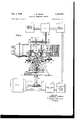
C- R. KENNY AUTOMATIC FREQUENCY CONTROL Filed April 22, 1943 5 Shets-Sheet 1 n l3 l4 CRYSTAL STABILIZED BEAT OSCILLATOR MIXER FREQUENCY SYSTEM AMPLIFIER 3 I03 FIG.1 1
I08 as 1 2 EEIEEIEB 8| .8: ,los H F I 104 X fi E :08 82 77 78 :03 as T as 1 I07 98 a4 99 |o2 85 IOI I06 95 96 .I ,l' I
s2 w r 6| '6 I5 I I I r r I I MOTOR W I DISCRIMINATOR MOTOR CONTROL AND CIRCUIT SCANNER CONTROL h SYSTEM INVENTOR CHARLES R; KENNY fi/ w ATTORNEY Nov. 2, 1948. c. R. KENNY 2,452,575
AUTOMATIC FREQUENCY CONTROL Filed. April 22, 1943 5 Sheets-Sheet 2 is 56 N 23 I l--! in b-l N N 8 Q \n m w h 2 3 1 I l C'E: r M r W58" N I F mmm, I #15 9 R L :38; INVENTOR E CHARLES R.KENNY ATTORNEY Nov. 2, 1948. R, KEN Y 2,452,575
AUTOMATIC FREQUENCY CONTROL Filed April 22. 1945 5 Sheets-Sheet 3 FIG. 3.
. INVENTOR CHARLES R. KENNY BEAT FREQUENCY AMPLIFIER C.R.KENNY AUTOMATIC FREQUENCY CONTROL Nov. 2, 1948.
5 Sheets-Sheet 4 Filed April 22, 1943 Nov. 2, 1948. c. R. KENNY AUTOMATIC FREQUENCY CONTROL 5 Sheets-Sheet 5 Filed April 22, .1943
INVENTOR CHAR? R. KENNY BY ATTORNEY Patented Nov. 2, 1948 AUTOMATIC FREQUENCY CONTROL Charles R. Kenny, Crestwood, N. Y., assignor to The Sperry Corporation, a corporation of Dela- Application April 22, 1943, Serial No. 484,103
29 Claims. 1
My invention relates to ultra high frequency control systems and is particularly concerned with automatic frequency control apparatus and methods for such systems.
In its illustrative embodiment, the invention will be described as employed for obtaining and maintaining constant output frequency during operation of an ultra high frequency oscillator of the type wherein an electron beam is passed through interacting hollow resonator means, but may be used generally with any type of tunable oscillator.
Considerable difficulty has been experienced in attempting accurate frequency control of hollow resonator type ultra high frequency devices, especially where the device is to be used for delivering any appreciable amount of power. Such devices normally require a long warming up period, usually measured in hours, during which the output frequency varies considerably before reaching a condition of temperature stabilization where a relatively constant output frequency may be expected. Moreover, such devices are very sensitive to drafts, changes in external air temperature, mechanical vibrations and the like which may unexpectedly alter their output frequency during operation.
Satisfactory frequency control of relatively low power ultra high frequency sources has been accomplished by employing a system consisting of a crystal controlled oscillator coupled to a frequency multiplier chain. But where appreciable power is needed along with frequency control, these crystal stabilized oscillators cannot be directly employed. My invention is especially adapted for accurate frequency control of relatively high power ultra high frequency sources.
It is a major object of the invention to provide novel automatic frequency control methods and apparatus for speedily obtaining and reliably maintaining a desired output frequency from an ultra high frequency source, or a desired frequency difference between two ultra high frequency sources. The invention is especially adapted for controlling high power in high frequency sources of the hollow resonator type.
A further object of the invention is to provide automatic frequency control methods and apparatus embodying novel frequency bandsweeping or scanning arrangements.
A further object of the invention is to provide A further object of the invention is to provide novel apparatus for repeatedly tuning a hollow resonator type ultra high frequency device over an appreciable frequency range.
A further object of the invention is to provide novel arrangements for controlling the operation of a frequency scanning system in automatic frequency control apparatus.
A further object of the invention is to provide automatic frequency control apparatus embodying novel thermally responsive tuning and tuning range scanning arrangements.
A further object of the invention is to provide novel electromagnetic tuning range scanning arrangements.
A further object of the invention is to provide novel direct current energized viscous damping or braking arrangements for an electric motor or the like.
It is a further object of the invention to provide novel automatic volume regulation or control arrangements, especially adapted for automatlc frequency control systems but not restricted thereto.
Further objects of the invention will presently appear as the description proceeds in connection with the appended claims and the annexed drawings, wherein:
Fig. 1 is a partly diagrammatic and partly sec- 30 tional detail view illustrating a preferred embodiment of the invention;
Fig. 2 is a combined wiring and diagrammatic view showing control circuit details of the invention;
Fig. 3 is a combined wiring and diagrammatic view illustrating a further embodiment of the in vention utilizing a simplified circuit;
Fig. 4 is a combined wiring and diagrammatic view illustrating a further embodiment of the invention utilizing thermally responsive tuning devices;
Fig. 5 is a graph illustrating and explaining the scanning operation of the circuit of Fig. 4;
Fig. 6 is a fragmentary wiring diagram illustrating an alternative manner of connecting the output of the control circuit power amplifier to the tuning motor;
Fig. '7 is a wiring diagram illustrating a further embodiment of the invention wherein a vacuum tube is employed in the direct current motor braking arrangements; M
Fig. 8 is a combined wiring and diagrammatic View illustrating a further embodiment of the invention utilizing electromagnetically controlled tuning and band sweeping; and
Fig. 9 is a graph illustrating the scanning operation of the apparatus of Fig. 8.
Referring to Fig. l, which illustrates a preferred manner of practicing the invention and details of a practical mechanical automatic tuning device for a source to be controlled as to frequency, ultra high frequency energy from a crystal stabilized oscillator system H and a controllable oscillator i2 is mixed in a suitable mixer it. The output of mixer it is an alternating voltage, the frequency of which is the difference between the ultra high frequency outputs of oscillators l i and 12. This difference frequency output of mixer 13 is of sufficiently low frequency that it may readily be handled in a conventional amplifier it and utilized in a phase sensitive discriminator and scanning control system l5, later to be described in detail, for actuating motor control circuit Iii to drive tuning motor ii of oscillator l2 to maintain the output frequency of oscillator 92 at a desired value.
The system of the invention will be described as employed to maintain the output of oscillator [2 at constant frequency.
Crystal stabilized oscillator system i i is of the above described low power type, preferably comprising a crystal controlled oscillator whose output frequency is appreciably below ultra high frequency ranges, but employing a. frequency multiplier arrangement for producing an output from system i i which is of a frequency very near that of oscillator 52. Since specific details of this system are not part of the present invention, further description thereof is not necessary, as any equivalent relatively low power system for obtaining a constant ultra high frequency near that desired for oscillator i2 may be employed.
Oscillator l2, as illustrated, is preferably of the hollow resonator type having output frequencies in the range of 3 X cycles per second or higher, and capable of delivering appreciable power output. Details of this device will be later described.
Mixer i3 is of any suitable type for receiving the two ultra high frequency source outputs and delivering to amplifier Hi a voltage having a beat frequency equal to the difference between the frequencies of system H and oscillator l2. This frequency difference will be hereinafter known as the difference or beat frequency. Since details of mixer 53 and amplifier it do not comprise part of the present invention, further description thereof is not necessary.
Fig. 2 illustrates details of the control arrangements comprising the major portion of the invention. The difference frequency alternating voltage is delivered to discriminator and scanning control circuit [5 across the transformer primary 58. The primary transformer circuit may be tuned to the required difference frequency by Variable condenser IQ. Transformer secondary 2| also forms a tuned circuit with variable condenser 22.
The difference frequency voltage from amplifier M is also fed to the center tap 23 of transformer secondary 2! through a condenser E l so that the phase of that voltage differs by 90 from that induced in secondary 2i. The opposite ends of secondary 21 are connected to the anodes of rectifiers 25 and 26, and the cathodes of rectifiers 25 and 26 are connected to ground through equal resistors 27 and 28. Alternating current by- pass condensers 29 and 5! are provided across the respective resistors. The center tap 23 is also connected to ground through resistor it.
In operation of the discriminator, the transformer primaries and secondaries are tuned to the desired difference frequency, and a quadrature phase component of the difference frequency voltage is added by Way of condenser 2. 3 to each of the voltages induced in each half of secondary 2!. These resultant voltages are rectified by rectifiers 25 and 23 during opposite half cycles, producing direct current flow I1, 12 in opposite directions through resistors El and 23, as illustrated.
When the difference frequency is constant at the desired value, that is when the output ire-- quency of oscillator 12 is constant and differs from that of oscillator H by the proper amount, the vectorial sums of the added difference frequency voltages are equal and the opposite currents I1 and I2 are equal. The equal voltage drops across resistors 27 and 28 provide equal bias voltages on control grids 32 and 33 of direct current amplifier tubes 36 and 35, respectively. Under these conditions, no control is necessary or provided in the system.
When the difference frequency is different from or. changes from its desired value, as where the output frequency of oscillator I2 varies, the primary voltage introduced at tap 23 is no longer in phase relation with the voltages in the tuned secondary halves. The vector sums of the added difference frequency voltages are now unequal, resulting in unequal unidirectional voltage drops across resistors 2'! and 28, the sense of the resultant of these voltage drops depending on the-direction of change in the difference frequency. Under these conditions, unequal vol-tages are applied to grids 32 and 33-, for initiating control operation to be hereinafter described.
The voltage drop appearing across resistor 73 is created by the sum of the currents I1 and I: flowing therethrough, and will appear whenever any difference frequency voltage is applied to the discriminator. Therefore this voltage drop indicates the existence of a difference frequency within the control range of the discriminator.
Tubes .34 and 35 and associated elements comprise a direct current amplifier circuit. The cathodes of tubes 34 and 35 are connected to ground through an adjustable cathode biasing and balancing resistor 35, and their anodes are connected through equal plate load resistors 3'! and 38 to ground through battery lil. Opposite currents I3, I; flow in the resistors as indicated. The voltage drops across resistors 3? and 38 also appear across voltage divider input resistors 39 and ll having adjustable taps connected to respective control grids 42 and 53 of a pair of tr;- odes All and 55 forming a balanced modulator circuit.
The plates of tubes M and 45 are connected to 'opposite ends of a transformer primary it whose secondary 4? is connected to control grids 48 and 49 of power amplifier tubes 5! and 52 of a power amplifier circuit. Condenser 4i" is connected across secondary ll and by-passes undesired alternating components of the transformer output. Resistor 5!] is the usual common cathode bias resistor connected between the cathodes of tubes 51, 52 and ground.
A source of alternating voltage 53, which may be the usual 60 cycle, volt line, is impressed across the primary of transformer 5 One terminal of the secondary of transformer 54 is con.- nected to ground through condenser 55' and the other terminal to a lead 55. The secondar of transformer 54 applies a modulating alternating voltage by lead 56 to the midpoint of transformer primary 46 connected thereto. A positive unidirectional voltage source 60 is also connected to this midpoint through a voltage-dropping and isolating resistor 55. Blocking condenser prevents iiow of direct current in the secondary of transformer 54.
The power amplifier comprising tubes 5i and 52 is a push-pull arrangement for amplifying the modulated output of the balanced modulator 5.4%, 45, and the output of the power amplifier 52 appears across the secondary of transformer 5i? which is connected across one field winding 5? of the two-phase tuning motor i? through condenser l H. The other field winding of motor I1 is connected directly to source 53, to be energized therefrom in phase quadrature relation with respect to the energization of winding 51.
Motor 1'! drives reduction gearing fil from which a shaft 62 extends to operate the tuning mechanism shown in Fig. 1. A second driven shaft 63 extends from gearing ii for rotating a cam 64 arranged to alternately move the shiftable arms of switches 65 and 66 to closed posi tion.
One terminal of switch 65 is connected to one side of the output of the direct current voltage amplifier 34, 35 above described by lead er. The corresponding terminal of switch 5 5 is connected to the other side of the amplifier output by lead 68. The other terminals of the switches are connected by common lead 69 to the plate of scanning control tube H. A lead i l connects tor 73 to the control grid ill of tube ii to provide a negative bias thereon when there is a voltage drop across resistor 13, a choke coil 16 being provided in this lead to impede the flow of radio frequency current. Condenser M is connected between grid l5 and ground, and together with the grid-cathode capacitance of tube ii is effective in by-passing radio frequency current. The plate of tube it is grounded for high frequencies through radio frequency bypa-ss condenser 69'.
Oscillator i2 comprises a stationary cylindrical barrel 1% enclosing resonator chambers l? and 13. Flexible end wall "l9 of chamber ll carries one of the spaced input grids ti, and flexible end wall 82 of chamber l8 carries one of the spaced output grids 83. Outer grids ti and 53 are rigid with enlarged external flanges 8 3 and while internal grids Bi and 83 are rigid with a third external flange 85 located intermediate the other two flanges. Flange 8G is rigidly secured to a base Bl, as by integral rib so.
Lever Si! is connected to transmit motion to flange '84 by an adjustable screw Q 3 and univcrsally jointed toggle pin 99. Similarly, lever $2 is connected to transmit motion to flange 85 by an adjustable screw l8! and universally jointed toggle pin E92.
A buffer resonator chamber 593 is formed with a flexible end wall EM. Grids 9 5 in the opposite end walls of chamber 183 are rigid with flange 85 and a fourth external flange idfi, respectively. A series of uniforml spaced adjustable screws 5533' (only one shown) are provided between flanges and H16. Similarly, several tension springs m8 (only one shown), anchored at opposite ends of flanges 84 and i take up mechanical play and keep the tuning adjustments positive.
Oscillator i2 is provided with a cathode I88 for projecting an electron beam successively through the resonators by way of their respective pairs of grids, and a feed-back loop I09 is provided for feeding energy from chamber 78 to the field within chamber ll to produce oscillations which may be extracted from buffer resonator its by wa of a concentric line connectic-n Hi3.
As shaft E52 turns in either direction, nut 85 correspondingly travels longitudinally thereof. Any suitable device such as a leaf spring 95' may be employed to hold nut 95 against rotation. When nut 95 travels away from hearing 9i, levers 2i and 92 are rocked about their fulcrums to simultaneously cause creased spacing of the input and output grids to gang tune resonators 'l'i and When nut $5 travels toward bearing 9'], springs [68 accomplish the reverse tuning operation by reducing the grid spacing in each pair. The buffer resonator may be tuned by adjusting screws tel and such tuning adjustment is not altered by the gang tuning operation above described. If desired a large coil spring (not shown) may be provided about shaft 62 to maintain the shaft under rotational stress and prevent mechanical lag or play in the system. Also, if desired, switches 65 and or their equivalents may be operated directly b the to and fro travel of nut 35 instead of by cam E i, which 1 tter is illustrated mainly for clarity of disclosure, or may be replaced a toggle switch thrown at each limit of travel of nut 95 by a suitable projecting yoke on nut No detailed mechanical disclosure is believed necessary to illustrate this arrangement.
Operation System ii and oscillator i2 are energized. The primary E8 and secondar: ill of the discriminator transformer are tuned to a frequency equal to the difference frequency which will obtain when ccsillator i2 is at desired output frequency with respect to reference frequency of system ii. This will be referred to as the desired diiference frequency. If the actual difference frequency output from amplifier i4 is not equal to the desired difference frequency, as will certainly be the case during warnnup conditions, the voltage drops across resistors and 28 will be different for reasons above explained in discussing the discriminator action. Whether the actual difference frequency is greater or less than the desired difference frequency determines which resister 2? or 28 has the gr ter voltage drop.
i he unequal voltage dro in resistors 27 and 28 are amplified in the c.-cct current amplifier 34, 35 and appear as unequal voltage drops across resistors 3? and till, respectively. These unequal voltages are applied to the control grids d2, 43 of the balanced modulator system 44, i5, wherein the relative magnitude 03. these control voltages determines the direction of control of the motor ll and of the output frequency of oscillator i2.
For example, should the voltage drop across resistor 3'! be larger than that across resistor 38, tube i l of the balanced modulator will be less conductive tube This means that alter- Is in the other transformer primary'half. The difference between these two alternating currents then represents, in phase sense and amplitude, the effective modulator output current. The induced output voltage in secondary ll will then be opposite inphase to this output current. On the other hand, should the drop across resistor 38 be larger than the drop across resistor'3l, the induced output voltage in secondary ll will be opposite in phase from its former value. Thus the sense of the actual difference frequency relative to the desired frequency determines the phase sense of the control voltage derived from the balanced modulator, that voltage being of predetermined phase when the actual difference frequency is the higher, and being 180 different in phase when the actual difference frequency is the lower.
The control voltage induced in secondary if is amplified in the power amplifier El, 52 and applied to motor winding '1. The voltages in the two-phase motor field windings 5'! and 59 are 90 apart in phase, and this relation may be exactly insured if necessary by inserting a phase shifting device of any known type be tween transformer 56 and winding Bl, or between source '53 and winding 59. Whatever the phase of the control voltage in secondary 5?, it will therefore appear in winding 5'! as 90 on either side of the voltage of winding 59, and therefore will determine the direction of rotation of motor An important part of the invention resides in the damping ofmotor l l, to prevent over-running or hunting. To this end I provide a resistor HI) connected as shown between a source of direct current (which may be source fit) and one end of winding '57, the other end being grounded so that a direct current is produced through field winding 5i. Blocking condenser l l i keeps direct current out of transformer 58. This direct current produces a magnetic flux linked with the motor rotor, which during operation provides a variable braking action that increases proportionately with the motor speed. The exerted damping torque is independent of the rotor position, there is almost no coasting of the rotor, and the motor speed tends to become a direct and nearly proportional function of the voltage applied to winding 5?.
Rotation of motor I! causes rotation of tuning mechanism shaft 52 to alter the frequency output of oscillator l2. Thus, should a signal corresponding to the actual difference frequency be fed into the discriminator, the above described operation is effective to tune oscillator l2 to its desired output frequency undercontrol of the discriminator. When that desired output frequency is attained, the actual difference frequency equals the desired difference frequency, the voltage drops across resistors 37 and 38 are equal, and there is no control voltage induced in secondary ll so that motor i'l leaves oscillator l2 tuned to the desired output frequency.
However, the output frequency of oscillator l2 may be so far different from that of system i i that the actual difference frequency is beyond the control range of the discriminator, whereby no difference frequency signal is derived from the output of the discriminator. Unless auxiliary measures are taken there will then be no control voltage in the system, and the frequency of oscillator l2 will be temporarily uncontrolled. In the preferred form of my invention, I solve this difficult problem by repeatedly tuning oscillater 12 over substantiall its entire tuning range,
8 detecting when an actual difference frequency is realized which is within the discriminator range, and then turning over frequency control of oscillator i2 solely to the discriminator and control action above described.
For this purpose, I use a scanning tube 7! which is a triode having a very high plate impedance when biased beyond cut-off, but a relatively 10w internal impedance otherwise. Rotation of cam 6 places tube ii in parallel with either of resistors 3'! or 38. Cam Ed is always in such position as to close either switch or switch 66. Tube H is normally maintained at zero bias, which is not quite the cut-off bias.
Assume now that oscillator I2 is energized but its frequency is such that no control voltage is obtained from the discriminator as above indicated, and that cam 64 happens to be positioned to close switch E56 as illustrated. Since there is then no voltage across resistor 13, tube H is conductive and it is connected by switch 66 in parallel with resistor 38. This unbalances the control circuit to produce a smaller voltage on control grid 43 than on control grid 42, just as if unequal voltage drops had been produced in the resistors 3? and 38 by discriminator operation. This unbalance causes operation of the tuning motor to tune oscillator l2 through its frequency range in one direction or sense of frequency variation. When the tuning limit in that direction is reached, cam 64 is of such design that it opens switch 68 and closes switch 55 to place tube ii in parallel with resistor 37, thus unbalancing the control circuit in the other direction, and causing motor H to tune oscillator l2 back across its entire range.
The above process is cyclic, and the apparatus continuously and repeatedly varies the oscillator frequency over, or scans, a wide frequency range so long as no frequency is presented which lies within the operating range of the discriminator. However, as soon as an oscillator output frequency is produced whose corresponding actual difference frequency falls within the discriminator operating frequency range, a condition which is immediately detected by my invention due to the appearance of a control voltage across resistor 13 in the discriminator, the above described discriminator action takes over to the exclusion of the scanning operation, and becomes effective to accurately bring oscillator I2 to its desired output frequency and keep it there.
Thus, when the actual difference frequency thus introduces a control voltage into the discriminator, a unidirectional voltage appears across resistor 13 and is applied as a negative voltage to grid '15, thereby rendering tube ll non-conductive. The operation of cam 54 is now ineffective to control the system, since tube H is an effective open circuit because of its high cutoff impedance, and no longer exercises any infiuence in the control circuit. Thus, through this phase of my invention, appearance of a signal in the discriminator output automatically eliminates actuation of the tuning mechanism by the scanning tube, and places the tuning mechanism under sole control of the discriminator. The negative bias for grid may be provided, if desired, directly from amplifier M, or in any equivalent manner, to signal that the difference frequency is within the discriminator range. Thus my scanning means, although preferably utilizing a portion of the circuit of and controlled by the discriminator, as already described, is operable 9 distinct from the operation of the discriminator.
The invention includes also automatic volume regulation for the control circuit. This is accomplished by lead 18 which feeds back a negative potential from resistor 13, for application to a suitable volume control device in amplifier M, such as to the grids of the amplifier tubes. As the amplitude of the dilference frequency voltage becomes larger, the potential on lead 18 becomes larger, and reduces the output of amplifier I l proportionately. Details of the actual connections within amplifier I 4 may be as in known automatic volume control circuits and need not be further described.
It will be understood that the illustrated direct current amplifier, balanced modulator and power amplifier may be replaced in the control circuit of Fig. 2 by any equivalent arrangement for converting the discriminator output to motor control voltages having the reversible phase-sense above described, without departing from the spirit of the invention.
My illustrated invention therefore provides a system which is speedily efiective to automatically tune a high power oscillator of the electron beam hollow resonator type to a desired output frequency and to maintain it there. The system is especially advantageous in the embodiment of scanning arrangements for extending control over a very wide arrange, and other novel control features. It will be understood that the invention of course is not limited to actuation of the particular tuning mechanism shown by way of example in Fig. 1, but may be equally well applied to any tuning mechanism or means for such oscillators, or for other types of oscillators susceptible of such mechanical or equivalent tuning control.
Furthermore, while the invention has been described as especially adapted for maintaining oscillator I 2 or some other source at constant output frequency, it is equally well adapted for maintaining any two ultra high frequency or other sources at a constant difference frequency, as is obvious from the above, regardless of variations in frequency in either source. For example, the invention may be employed for maintaining the local oscillator of a heterodyne system in fixed frequency relation to a received signal. Similar applications of the invention are obvious.
In the above, as in all hereinafter described embodiments of the invention, scanning is accomplished by continuous wave energy actuating the oscillator tuning mechanism.
Further embodiments Fig. 3 illustrates a further embodiment of the invention wherein the separate balanced modulator of Fig. l is eliminated. The diiiference frequency amplified at M passes through a discriminator, as before, and the discriminator output is impressed on a combined voltage amplifier and modulator circuit containing tubes H2 and H3, similarly to Fig. 1.
In Fig. 3, instead of groundin the common connection between load resistors 21 and 28 of the discriminator, I connect that common connection back to tap 23 of the transformer secondary 2i through a lead H4. The common connection between the resistors is therefore maintained floating with respect to ground. If necessary, compensating condensers H5 and H6 are provided in the transformer input and output circuits. Resistors H1 and H8 serve as 10 input resistors for the voltage amplifier H2, H3, and these resistors are provided with low frequency by-pass condensers H9 and 12! for eliminating alternating components from the discriminator output.
The direct current output of the voltage amplifier and modulator circuit is modulated by introduction of a small alternating voltage in series with the common cathode circuit, as illustrated. The alternating filament supply voltage for tubes H2 and H3, derived from source E22, is impressed across a resistance I23 which is center-tapped to ground, and one leg of the common filament circuit is connected through common variable bias resistor I24 to an adjustable balancing tap on the differential cathode biasing resistor I25. This provides a small alternating voltage between cathode and ground in each of tubes H2 and H3 for modulating the plate current in each tube circuit. Thus, whereas in Fig. 2, the voltage amplifier 34, 35 produced a direct current output which resulted in unidirectional voltage drops across resistors 33' and 38, the voltage amplifier H2, N3 of Fig. 3 has an alternating current output.
The opposed alternating currents I7 and Is in the voltage amplifier output produce corresponding alternating voltage drops across resistors 3'! and 38, and coupling condensers I26 and i2? permit only the alternating components of these voltage drops to appear across input resistors E28 and i251 and on the control grids 48 and as of tubes 5! and 52 of the power ampliiier. Resistor 35 is the screen voltage dropping resistor for tubes H2 and H3, and resistor 132 in the screen grid circuit of tubes 5| and 52 provides direct Voltage to the latter screen grids, the usual screen grid by-pass condenser being indicated at E33.
In operation, the polarity of the discriminator output determines which of currents I7 or Is is larger and therefore determines the phasesense and amplitude of the output of the power amplifier 53, The output voltage across the secondary of transformer 56 therefore depends in amplitude upon the amplitude of the difference frequency voltage from amplifier l4, and depends in phase-sense or polarity on whether the actual difference frequency is greater or less than the desired difference frequency, as in Fig. 2. Utilization of the output of transformer 56 to actuate the tunin mechanism of oscillator i2 is the same as in Fig. 2.
The scanning control arrangements are also different in 3. The scanning control tube is here a multi-purpose tube such as a duo-di odetriode 23 The triode section operates in the same manner as the tube "ii of Fig. 2. The diode section s used to provide the negative cut-off bias f 1 the triode section, and for this purpose rectifies version of the output of amplifier is, being connected to the output thereof through a blocking; or coupling condenser F35. A portion of the resulting lilidllECtlOliDl voltage appearing across resistors i-N and i3! is filtered by by-pass condenser and applied to the control grid Hit? of the tricde section of tube Hi l. This same voltage may also be used as the automatic volume control voltage for amplifier id on lead '28.
I have found that the impedance of the triode section of tube 53f is normally insufiicient to unbalance the modulated output of the voltage amplifier 5 i2, H3 when placed in parallel with either resistance 31 or 38 by operation of the 'is connected across a resistor switchesfitftfi'controlled by can a as in Fig.2.
To remedy this I provide means whereby the output of tube H34 produces the desired un- 'Switch output leads '67 and 68 are grounded through radio frequency blocking and by-pass condensers Hi7 and M6 to prevent direct current return to' ground, and to preventany transi'ent switching effects.
During scanning, the motor-driven earn-controlled switch 6d alternately places the 'triode section of tube I34 in parallel with tube I12 or H3, as in Fig. 2. For example, when switch 54 is positioned as illustrated, the triode section of tube I33 and tube M3 then have a common load resistor 35, and the resultant voltage drop across resistor 38 produced by both tubes I34 and'II3 is suflicient to unbalance the motor control circult just as if the discriminator were exercising control. Reverseunbalance is obtained when switch 55 is closed, with switch 55 open.
. The above scannin operations continue cyclically, as in Fig. 2, until a voltage passed by condenser 135 indicates that the actual difference frequency is within the discriminator control range, and results in the above-described unidirectional drop across resistors 536 and I37. This provides a negative bias on "grid I48, thereby'cutting off the tube and eliminating its scanning control function, the discriminator action now assuming control of tuning.
The above arrangement is especially advantageous in that control of the scanning arrangements and automatic volume control are independent of the discriminatoroutput, and automatic volume control is maintained While tube I34 is non-conductive as well as during scanning. Other than above described, the apparatus of Fig. 3 functions similarly to that of Fig. 2, and the various modifications of Fig. 2 may also be applied to Fig. 3.
Fig. 4 illustrates anembodiment of the invention wherein tuning of oscillator I2 is accomplished through thermally responsive devices.
The discriminator in Fig. 4 is substantiall the same as that of Fig. 2 as indicated by corresponding reference characters, resistor I43 corresponding to resistor 73 of Fig. 2. However, the junction of resistors 27 and 28 is here not grounded, but by-pa-ssed to ground by condenser One side of the discriminator output is contual output frequency of oscillator I2 difiers only in a predetermined direction from the desired output frequency. The drop across output 'retherefore provides a negative bias sistor I I grid 15:.
vtitagertr thecontrol gnultzsr'a scanning cont roltube I53; and the magnitude of thisvoltag'e,
.whieh de'peiids on thej'mag'riitude of thedifference irequency'infthe smeared-direction, Conn-01s cur- 'rentflowtlirbu'ghtub'e I53.
suitable alternating'cur'rent source 756.
The 'output'circuit of tube I53 contains the primary of transformer I57, whose secondary serves 'asth'e'input of a'push pull power amplifier j circuit likethat ofFi'g. 2. condenser :58 blocksdirect current fr'oin'the primary of transformer I57,
the anode voltage for tube I53 beingsupplied from 'a source I50 through'a resistor Iiafl. The power amplifierI59, IBI. has substantially L the sameelementsastnat ofFig. 2, comprising jtube's I59 and IN connectedin push-pull and 'having'a commonjcath'ode bias resistor I52 and by pa'ss condenser IE3. Thesecondar or transfo'rmerl57'is connected at opposite ends to control grids I64 and I65 of tubes'I5'9and IGI, re-
ssecuve1y,anu has'its center tap grounded. The butputof thepo w'er amplifier is derived from the secondar of output transformer I I56, which corresponds to transformer '56 in Fig. 2, and ener- 'giz'sj the thermal tuning devices, one end of the secondary being connected to the grounded rmin orosc uator I2, and the other end of the secondary being connected to one terminal of a toggle'sw'itch l'fil P I "'Flang'es"84,'35'and'liii, whichare attached to the 'oscillat'or tubdgrids as' shown in Fig. 1, are here jurge'd'apart by compression springs I68 and I69. Flangesfsfi and"are' provided with rigid radial Conductive projections I79," I to'which are secured the opposite ends of thermal struts or wires I 7I and I72. The adjacent ends of the thermal strut wires are secured to a co'm m'o'n terminal I 73 carried by 'fiangeQSE but insulated therefrom'as by insulator block I74. Te'r'm'inal 73 is connected to thectner'terminarof switch I57. Switch 567 is "held rigid with "flange"84," as by illustrated support I75, and 'is'of the"well known toggle type "which snaps "between 'open and closed limit "positions. H a p flSpringsIBBfand159' normally maintain'wires n; an I72'taut, and loose'collars I76 and m, "pi'ef'e rablybf some electrical and heat insulating material, are provided surrounding the respective wires 'forp'rotectingagainst local drafts and temperature' changes.
Flange'BE carries a rigid switch actuating arm I78 carrying a yoke I79 operating toggle switch lever I80. When'switch-lever' I89 is in its closed position, strutsI7I and I72 are connected electrically inparallel across the output of transio'rmer' I56, andwill'be energized by said output. When there is no signal issuing from the di crimina'tor, the outputof tube I 53 corresponds to an amplified version of the modulating voltage derived from source I56, and this output energizes the scanningjoperation' of my system.
Assume that oscillator I2 starts cold, and that no signal from the discriminator is provided on The output frequency of the oscillator isno'w maximum. Switch lever I 80 is disposed in "the illustrated closed position. Energization of struts I7 Iand I72 b current from the output of tube I53 expands them, and permits springs I68 and T69 'to separate 'theflanges, thereby altering the grid spacing to gang tune the oscillator to decrease its frequency.
"After struts I7I'and 'I72 have expanded a certain amount, usually corresponding to the entire tuning range of oscillator I2, switch lever I80 is moved sufiiciently by yoke I'IS to snap to its open position to break the circuit. Struts I'll and I12 then begin to cool, and their contraction during cooling tunes the oscillator back over its range until yoke I19 again snaps the switch closed to reenergize the struts and repeat the first part of the operation. It will be clear that switch I67 could be operated by relative motion between flanges 84 and 86, or 86 and 85, if desired.
The above operation is cyclic and will repeat in like manner as long as sufficient energy is received from transformer 66 to energize the tuning struts, and until a control signal is received from the discriminator. Tube I53 is of such nature as to have predetermined conductivity when the grid has zero bias, and its conductivity is reduced as the grid bias becomes more negative.
Fig. illustrates the frequency response of the discriminator as the actual difference frequency A changes. The dotted line positive part of the curve represents the discriminator output voltages which are ineffective due to the effect of diode 49 in the circuit, and only such difference frequencies as produce negative discriminator output are effective to control tuning, as will be explained.
As the oscillator frequency decreases, the difference frequency also decreases, approaching the solid line discriminator range illustrated in Fig. 5. During this sweeping, a positive discriminator output voltage is first obtained, corresponding to the dotted portion of Fig. 5. This positive voltage is blocked by diode I59, so that no voltage is produced across resistor I54. When the actual difference frequency passes the desired value, corresponding to point C, the polarity of the discriminator output reverses, and provides a negative bias on grid H52 which becomes more negative as the frequency continues to change in that direction. As grid 552 becomes more negative it reduces conductivity of tube I53, and the reduced output of tube I53 causes the thermal responsive devices to vary the oscillator frequency at a slower rate.
Eventually, when the negative bias of tube I53 becomes suflicient to so reduce the output of tube I53 that such output merely maintains the tuning struts at a relatively constant temperature while supplying losses due to radiation, etc., the system becomes substantially balanced to thereby hold oscillator l2 at the corresponding frequency level. This balance will take place, for example, when the descending difference frequency reaches the point B on the curb in Fig. 5.
Should the difference frequency now change in either direction from point B, the resultant increase or decrease in the output of tube 253 will heat or cool the tuning struts. The resultant change in frequency will produce a change in control voltage across resistor I5I so as to restore the oscillator frequency toward its former value, corresponding to point B of Fig. 5. In practice, I have observed that the above-described thermal control maintains the output frequency of oscillator I2 within a range of about 5 kilocycles, when operating at about 3600 megacycles which is satisfactory for most purposes.
It will be noted that here the discriminator can take control away from the scanning mechanism only when the oscillator and difference frequencies are decreasing. For, with increasing frequency, the switch I6! is open, and no control tor.
14 action, other than frequency change with strut cooling, possible.
The apparatus of Fig. 4 thus embodies thermally responsive tuning control means for scanning a frequency range, and arrangements for detecting and applying a discriminator output signal to take over automatic tuning control of the oscillator 52 while suppressing the scanning operation.
It will be noted that, referring to Fig. 5, the descending difference frequency passes through the point C which represents the point where oscillator I2 is at desired output frequency and is theoretically an optimum control position. However, since at this point there is no discriminator output and the bias of grid I52 is zero, the scanning operation is not affected, and it is not until the oscillator is slightly off frequency in the region A that the control action above-described is possible. By making the system very sensitive, the frequency at point B will differ immaterially from that at point C.
Obviously the output of transformer I66 in Fig. 4 be employed to operate a motor such as that at i? in Fig. 1 for tuning the oscillator in one direction over the scanning range. Return scanning movement may be had by means of a suitable releasable clutch and spring bias in the motor drive, for example.
Referring to Fig. 6, which illustrates an alternate manner of connecting the output of any of the systems of Figs. 2 or 3 to the motor, the plate circuits of tubes SI and 52 are connected directly across field winding 51 of the tuning mo- Direct current is prevented by condenser 82 from flowing through one half of winding 51. A resistor I8i conducts direct current from source I59 to tube 5i. In the usual push-pull circuit the opposite unidirectional plate currents in the halves of the primary of the output transformer magnetically cancel each other out, but the above arrangement insures against such action and provides a relatively constant direct current energization of winding 5i. Operation is the same as described in Fig. 2, with the direct current energized winding providing reliable damping and braking and with the advantage that the apparatus is simplified by elimination of trans-- former 56. If needed, a phase control condenser 583 may be used in the circuit of motor winding 59.
Referring to Fig. '7 wherein there is illustrated another embodiment of the present invention, a further type of direct current damping arrangement for the tuning motor I! is illustrated, adapted for use in a manner similar to that disclosed in Fig. 2. In this figure, parts similar to those shown in Fig. 2 are referred to by similar reference numerals. A rectifier I84 and its output resistor I85 are connected across the output of transformer 58. By-pass condenser I86 eliminates alternating current from the unidirectional voltage drop which appears across resistor I85 Whenever a motor driving signal appears in the output of transformer 56. This direct current voltage varies in strength proportionally to the departure of the actual difference frequency from the desired difference frequency, and is zero when there is no signal from the dis-- criminator and maximum when the signal from the discriminator is strongest. It is applied to control grid I81 of normally non-conductive triode I88 through a biasing battery I89 which keeps the grid from going positive during normal operation. A source of positive potential I50 is connected to the anode of tube l83 through motor winding 5i. Blocking condensers Edi keep the direct current out of transformer 56. The polarity of this direct current is thus independent of the direction of rotation of the motor or of the sense of deviation of the actual difference frequency from the desired difference frequency.
In operation, whenever a motor control signal appears in the output of transformer 5'6, a ver sion of it is rectified and applied to the grid of normally blocked tube ltd to initiate flow of di rect current through winding 5?. As the motor control signal increases in strength, tube 588 is made more conductive, thereby increasing the damping action for higher motor control voltages, corresponding to higher motor speeds.
However, when there is no motor control sig nal from the discriminator, as during scanning, the scanning voltage produced by unbalance of the modulator by the scanning control tube is not of sufi'icient amplitude when rectified by rectifler I84 to overcome the bias of battery :39. Accordingly, tube i883 remains non-conducting during scanning, and no damping is produced during such scanning.
In this embodiment, therefore, I have provided a direct current damping arrangement for the tuning motor which is inversely proportional to the departure of the actual output frequency of oscillator l2 from the desired output frequency. There is no damping during scanning, and the damping is maximum during the period the discriminator action controls.
In any of the above-described direct current damping arrangements, the direct current for braking may be introduced into the fixed phase winding 59, if desired. The damping arrangements of Figs. 2, 6 and '7 may be interchangeably employed in any tuning motor control apparatus. The damping control circuit of Fig. '7 may of course be used directly in the system of 3 and will operate therein exactly as just described.
Fig. 8 illustrates a further embodiment of the invention wherein there is disclosed a cyclic tuning arrangement which is employed with part of the circuit of Fig. l as indicated and as a substitute for the thermal tuning devices of Fig. i. Here, too, the parts similar to those shown in Figs. 2 or 4 are referred to by similar reference numerals.
Oscillator flanges Ed and 85 have rigidly secured thereto a pair of U-shaped soft iron pole pieces I92 and ltd having adjacent pole faces spaced by a small gap. Similar cooperating pole pieces 19:: and H95 are rigidly attached to flanges 85 and 85. The outer ends of thepairs of "pole pieces are secured together by flat steel spring bars I96 and I97. The respective pole pieces carry series connected windings tea and 899 as illustrated, so that the respective adjacent oscillator flanges are interconnected by electromagnets. Spring bars file and it? resist relative displacement between the associated pole pieces, so that the electromagnets are flexible and elas tic.
Arm 2M and yoke 2%2 operate toggle switch lever I88 as in Fig. '4. Switch lt'i is mounted stationary with flange il i as illustrated. The plate circuit of a scanning control tube 263 is connected in series with the electromagnet windings and switch liil. A variable tap is provided at 204 on one of the electromagnet windings for adjusting the effective ampere turns to adjust the relative strength of the electromagnets. This provides a differential tuning adjustment forreli6 atively tuning the resonators. A condenser 255 is preferably employed to improve the rate of response of the electromagnets to the tuning signals.
The discriminator output is connected between control grid 2% and the cathode of tube 293. The usual screen grid voltage dropping resistor is indicated at rill, and the cathode is maintained above ground potential by biasing resist-or 2%.
Assume that oscillator 62 starts cold with no signal from the discriminator. Since the de-e'nergized magnet springs I95, it! tend to force the flanges apart, the resonators of the cold oscillator are initially at lowest resonant frequency, just opposite to the situation of Fig. 4. The armplified plate current of tube 263 provides direct current energization for the electromagnets, switch it'd being closed. The opposite poles of the electromagnets attract each other, thereby moving the attached flanges to tune the oscillator over its range in one direction. At the limit of such tuning movement, yoke 2522 throws switch ldl' open, thereby de-energizing the electromagnets to permit separational tuning motion of the flanges under control of springs let and 91. If desired supplementary springs such as at 168,
i239 may be used to assist this return.
Dashpots 2E5, effectively between the poles of the flexible electromagnets, may be provided to oppose attraction of the poles and produce a relativel slow, uniformly increasing frequency rise in oscillator 52. This is advantageous to avoid danger of running past discriminator control point B of Fig. 9. The dashpots do not 01)- pose separation of the poles which takes place when the magnets are de-energized, so that the time of return sweep from high to low frequency in the scanned range is relatively short and fast as compared to the opposite sweep.
The above operation is cyclic and repeatedly tunes the oscillator over its entire range. It is substantially the same as the thermal tuning arrangements except that the tuning movements are oppositely energized.
When a negative bias due to a signal from the discriminator appears on grid 2%, the output of tube 293 is cut down proportionally to the signal strength. This gradually slows and stops the tuning movement, similarly to the operation of Fig. l, and substantial balance is achieved when the output of tube 283, as opposed by the mechanical load on the electromagnets, is insufficient to cause tuning movement from a tuned condition such as point B on Fig. 9.
As shown in Fig. 9, the discriminator action of the circuit of Fig. 8 is opposite to that of Fig. the existence of an actual difference frequency within the discriminator range being detected only when the frequency is increasing. For this reasonythe discriminator output terminals when used with Fig. 8 are reversed with respect to Fig. 4, as shown by Fig. 9. Otherwise operation is substantially similar to that of Fig. 4.
As many changes could be made in the above construction and many apparently widely different embodiments of this invention could be made without departing from the scope thereof, it is intended that all matter contained in the above description or shown in the accompanying drawings shall be interpreted as illustrative and not in a limiting sense.
What is claimed is:
1. Frequency control apparatus comprising a variable frequency source, frequency regulation means for said source, balanced circuit means having a differential output, means for actuating said frequency-regulation means in response to said output, means for unbalancing said circuit means to actuate said regulation means in one direction whereby said source frequency is varied in a corresponding direction, and means controlled by predetermined actuation of said regulation means for reversing the sense of unbalance produced by said unbalancing means, whereby said source frequency is varied in an opposite direction.
2. Electronic apparatus comprising variable frequency means, frequency regulating means for said variable frequency means, a balanced control circuit having a differential output for actuating said frequency regulating means, directional tuning control means for selectively unbalancing said circuit in one sense or another to produce a corresponding direction of actua tion of said regulating means, and means actuating said control means by said frequency regulating means at two predetermined conditions thereof for cyclically operating said frequency regulating means so as to repeatedly scan a predetermined frequency band determined by said conditions.
3. The apparatus defined in claim 2, comprising means responsive to a frequency condition dependent on the frequency of said variable frequency means for rendering said unbalancing means inoperative and thereby halting said frequency scanning.
4. Frequency control means comprising a variable frequency source, frequency regulation means for said source, reversible motor means for actuating said frequency regulation means, a motor control circuit for said motor means, including balanced modulator means having a balanced input circuit and adapted to produce an alternating reversible-phase variable magnitude output signal corresponding in phase-sense and magnitude to the sense and magnitude of unbalance of said input circuit, a normall conducting electron discharge tube, means selectively coupling said tube to unbalance said input circuit in either sense, whereby said motor'means and frequency regulation means are actuated in a corresponding sense to correspondingly vary said source frequency, and means responsive to two predetermined conditions of said regulation means for actuating said coupling means to reverse the sense of unbalance of said input circuit, whereby said source frequency is scanned between two predetermined limits corresponding to said conditions.
5. Frequency control apparatus comprising a variable frequency source, frequency regulation means for said source, reversible motor means for actuating said frequency regulating means, a motor control circuit, an electronic discharge device, switching means for periodically inserting said device into said motor circuit for oppositely energizing said circuit for repeatedly tuning said source over a predetermined frequency band, and means responsive to a frequency condition dependent on the frequency of said source for controlling the conductivity of said electron discharge device to thereby vary the effect of said tube in said circuit.
-6.- Frequency control apparatus for an ultra high frequency device comprising a thermally expansible tuning strut on said device, resilient means opposing expansion of said strut, a switch controlling energization of said tuning strut, and means responsive to expansion and contraction 18 of said strut for controlling said switch for periodically energizing and de-energizing said strut to produce corresponding periodic expansion thereof.
7. Apparatus as in claim 6, further including means responsive to the frequency of said device for producing a control signal and means for controlling the energization of said strut in response to said signal to interrupt said periodic energization and maintain said frequency at a desired value.
8, Frequency control apparatus comprising a cavity resonator having spaced tuning members, an electromagnetic tuning device disposed between said members, said device being adapted when energized to effect relative displacement of said members, and resilient means forming a part of said electromagnetic means for effecting opposite relative displacement of said members.
9. Automatic frequency control apparatus comprising a variable frequency source, frequency regulation means for said source, motive means for actuating said frequency regulation means, means responsive to actuation of said frequency regulating means for controlling operation of said motive means to cause said source frequency to scan a predetermined frequency band, means providing a signal representing variation from a desired frequency condition, and means responsive to said signal for controlling said motive means to maintain said desired frequency condition and for rendering said operation controlling means inoperable to vary the frequency of said source.
10. Automatic frequency control apparatus comprising a variable frequency source, frequency-regulating means for said source, motive means for actuating said regulating means, means responsive to actuation of said regulating means for controlling operation of said motive means to cause said source frequency to scan a predetermined frequency band, means responsive to approach of said sourcefrequency toward a desired value for producing a control signal, and means responsive to said signal for rendering said operation-controlling means inoperative to vary said source frequency and for maintaining said source frequency at said desired value.
11. Apparatus for automatically maintaining a desired frequency difference between two sources comprising means for regulating the frequency of at least one of said sources, means controlled by said regulating means for cyclically operating said frequency regulating means to scan said regulated source frequency over a predetermined frequency band, means providing a signal representing variation from said desired difference frequency, means responsive to said signal for interrupting the operation of said cyclically operating means, and further means responsive to said signal for controlling said frequency regulation means to maintain said desired frequency difference.
12. Automatic frequency control apparatus comprising means providing a signal representing variation from a desired frequency condition, frequency regulation means for said apparatus, a motor for driving said frequency regulation means, means cyclically controlling said motor for scanning a predetermined frequency band, means responsive to said signal for rendering said motor control means inoperable when said signal is of a frequency value lying between predetermined limits, and means responsive to said signal for assuming control of said limited fretan-52 575 fe quency regulation means when said eyclicfmotor control means is inoperableto minimize said vari- =ation from the desired frequency condition.
13. Automatic frequency control apparatus comprising means providing a signal representing variation froma desired frequency'con'dition, electromagnetic frequency regulation means for said apparatus, means forcyclically actuating said frequency regulating means for scanning -a predetermined frequency-band, means responsive to said signal for rendering said scanning means inoperable when said signal is of 'a frequency value included between predetermined limits, and-means responsive to said limited signal for assuming control of said f lequenc-y regulation means to reduce said variations to a minimum when said scanning means is inoperable.
14;Automatic' frequency "control apparatus comprising means providing a signal representing variation from-a desired frequency condition, thermally responsivefrequency regulation means for said apparatus, means under the 'contr'ol of said frequency regulating means for cyclically actuating said frequency regulation means 'for scanning a-pred'eterniined frequency'band, means responsive to'said signal for rendering said scanning means inoperable and for assuming control of "said frequency regulation imea'ns when said scanning means 'is inoperable.
15. Automatic frequency control apparatus comprising frequency regulation means, motor means driving said frequency regulation means, means providing as'ignal controlling =op'eration of said frequency regulation meansy-means ;providing damping substantially V proportional to the speed of said motor,"an'd meansaresponsive"tosaid signal for modifying'the'damping action'oi said damping means.
'16. Automatic volume control apparatus fora variable frequency source comprising a .controllable amplifiercoupl'ed to'said source'a frequency discriminator coupled to said amplifier, s'aid discrimin'ator comprising means for deriving span of voltages of the frequency of said sourcef and varying "in magnitude oppositely in response to change in frequency of said source, -afpair of 5 rectifiers 'forrectifying said voltages, ea'ch-of sai'd rectifiers havingia respective l0ad=resistoranda load resistor common to both said rectifiers, 'means responsive to the difference between the voltages appearing across saidr'es'pective load resistors for controllingithefrequency of said' source -i'n adirectionto restore said s'ource'ire'qu'ency toward a desired value, and means responsive to the voltage appearing across'said common load resistor for controlling the output fromsaid'am- 'pli'fier.
1'7. Automatic volume control apparatus fora variable frequency circuitcomprising acontrollable amplifier coupled tosaid crcuit, a'frequency discriminator coupled to said amplifier and comprising a tuned center-tapped circuit, a resistor connected between the center'tap of said tuned circuit'andground, a rectifier and'lo'adresis'tor connected in series between each end of said tuned circuit and groundgmeansfor controlling the frequency of said variable =frequency'circuit in response'to the difference between the-voltages appearing across s'aid' lo'a'd resistors, and means for controlling the output'of said amplifier by the voltage appearing across said first resistor.
:=-1'8.-'Automatic frequency control "apparatus comprising frequency regulation means, automatic means for actuating said frequencyregu- 253i lation-meansin response toasignal represen g a version of a desired frequencyconditionfmeans for damping the actuationof'said frequency regulation means, *andmeans responsive to 'said signal for controlling-said damping-means.
19. Frequency control apparatus comprisinga circuit to be controlled, a motor actuating-said circuit and having a winding, means for pr'oducing an alternating current signal for controlling said circuit, means for applying said-signal to said winding, means for energizing *said winding by direct current, and means for controlling said direct current energization by' 'said signal.
20. Automatic frequency control apparatus comprising a variable frequency source, motor driven tuning means for said source, a motor controlcircuit, means a'ctuated by said 'tuning mean's for periodically oppositelyenerg'izing said motor control circuit-for reversibly operating said-motor -to repeatedly'tune said source 'over-a predeterniined frequency band, frequency sensitive means providing a signal representing variation -from' 'a desired frequency condition determined at least in part by said source,means-for'introducing said signal into said motor control circuit for-energization of the latter, and means responsive to said signal for rendering said periodically energizing means inoperablewhen said signal is Withinthe'range of said-frequency sensitiverneans.
21. Automatic "frequency control apparatus comprising a source, electrically responsivetuning means for said source, -control'circuit' for said tuning means, means'eifective 'on said-circuit and operated'bysaid'tuning means'for'c'yclically operating said tuning-means for repeatedly scanning a predetermined frequency band, means providing a signal representing clepartureiroma predetermined frequencycondition, and means responsive to said'signal for-actuating said'control circuit tomaintain'said source frequency-at said predetermined frequency condition and for simultaneously limiting ener'gization of said con- :trol circuit to prevent actuation of said-scanning means.
.'22.' The apparatus defined'in claim-21, wherein said control circuit comprises an electron dis- ''charge device, and said signal is applie'ii to a control electrodein said device.
23. Frequency controlled apparatus "comprising a variable frequency device having relatively movable frequency-adjusting menibers, electri- "cally 'energizable force ex'erting means between said members, resilient means opposing said force-exerting means, means for-producing 'a si'gnal\for'controlling said force-eXer-tingmeans to vary the'frequency of said devioedn a predetermined direction, means responsive to a predetermined frequency variation ofsaid device Tor deenergizing said force-exerting means, -Whereb'y said resilient means causes said 'rrequency m vary in an oppositedirection, 'means respo'n's'ive to a predetermined frequency variation of said G5 device in said opposite direction for -again*energizing said'force-exerting means to vary said-frequency in said first directiomwher'eb'y saidfiequency is scanned periodically over a'pre'determined range, means for producingasignal-corresponding to variation of said 'frequenc'y' -from a desired value, and means responsiveto said *latter signal for limiting*said' firstsignal to a value substantially producing said desired frequency value, whereby said scanning {is "halted and' s'aid desired 'frequen'cyv'alue maintained.
24.-'Frequeney control apparatus for a variable '21 frequency device having relatively movable frequency-adjusting members comprising electrically controlled extensible means positioned between said members, means for energizing said extensible means to vary the frequency of said device in a predetermined direction, means responsive to a predetermined frequency variation of said device for deenergizing said extensible means, whereby said frequency varies in an opposite direction, means responsive to a predetermined frequency variation in said opposite direction for again energizing said extensible means to vary 'said frequency in said first direction, whereby said frequency is scanned periodically over a predetermined range, means for producing a signal cor responding to variation of said frequency from a desired value, and means responsive to said signal for limiting the energization of said extensible means to the value producing said desired frequency value, whereby said scanning is halted and said desired frequency value is maintained.
25. Frequency control apparatus comprising a variable frequency source having frequency regulation means, frequency discriminator means responsive to the output of said source and adapted to produce a discriminator output signal corresponding in sense and magnitude to the direction and magnitude of deviation of said source frequency from a desired value, a source of power frequency energy, modulator means coupled to said power frequency source and responsive to said discriminator output signal for producing an alternating output signal of said power frequency having magnitude and phase-sense respectively corresponding to the magnitude and sense of said discriminator output signal, reversible motive means for said regulation means coupled to said modulator means and adapted to adjust said regulating means in a direction corresponding to the phase-sense of said power frequency signal and in a direction to restore said source frequency toward said desired value, means for causing said modulator means to produce an output to actuate said motive means independently of said discriminator output signal, and means responsive to an input signal to said discriminator means for rendering said last-named means inoperative.
26. Frequency control apparatus comprising a variable frequency source having frequency regulation means, frequency discriminator means responsive to the output of said source and adapted to produce a discriminator output signal corresponding in sense and magnitude to the direction and magnitude of deviation of said source frequency from a desired value, a, source of power frequency energy, modulator means coupled to said power frequency source and responsive to said discriminator output signal for producing an alternating output signal of said power frequency having magnitude and phase-sense respectively corresponding to magnitude and sense of said discriminator output signal, reversible motive means for said regulation means coupled to said modulator means and adapted to adjust said regulating means in a direction corresponding to the phasesense of said power frequency signal and in a direction to restore said source frequency toward said desired value, said modulator means comprising a balanced circuit and further including means for unbalancing said circuit whereby said motive means will be actuated independently of said discriminator output signal and means re sponsive to rotation of said motive means beyond a predetermined limit in either direction for reversing the sense of said unbalance, whereby said motive means will thereby actuate said frequency regulation means to vary said source frequency in a reverse direction, and means responsive to an input signal to said discriminator means for rendering said unbalancing means inoperative.
27. Frequency control apparatus comprising a variable frequency source, frequency regulation means for said source, reversible motive means coupled to said regulation means for actuating said regulation means to vary said source frequency, balanced circuit means coupled to said motive means to actuate said motive means in a sense corresponding to the differential output of said balanced circuit means, means for unbalancing said circuit means, whereby said motive means is actuated in a corresponding sense, and means responsive to attaining either of a pair of predetermined positions of said frequency regulation means for reversing the sense of said unbalance to vary said source frequency in an opposite direction, whereby said source frequency is cyclically varied between two limits determined by said two positions of said frequency regulating means.
28. Apparatus as in claim 27, further including means responsive to a source frequency value in the neighborhood of a desired value for rendering said unbalancing means inoperative, whereby the cyclic scanning of said motive means is interrupted.
29. Apparatus as in claim 27, further including means responsive to a source frequency value in the neighborhood of a desired value for rendering said unbalancing means inoperative, whereby the cyclic scanning of said motive means is interrupted, and further including means for producing a control 'signa1 corresponding in sense and magnitude to the sense and magnitude of deviation of said source frequency from said desired value, and means for actuating said balanced circuit means by said control signal to produce a corresponding motive means control signal adapted to actuate said motive means to vary said source frequency towards said desired value.
CHARLES R. KENNY.
REFERENCES CITED The following references are of record in the file of this patent:
UNITED STATES PATENTS Number Name Date 1,855,152 Jones Apr. 19, 1932 1,934,400 Bollman Nov. 7, 1933 2,012,603 Fuchs Aug. 27, 1935 2,041,855 Ohl May 26, 1936 2,151,127 Logan Mar. 21, 1939 2,173,902 Gerth Sept. 26, 1939 2,190,319 Koch Feb. 13, 1940 2,196,402 Snyder Apr. 9, 1940 2,210,781 Shofstall Aug. 6, 1940 2,227,467 Sweeny Jan. 7, 1941 2,285,016 Carlisle June 2, 1942 2,287,925 White June 30, 1942 2,311,658 Hansen Feb. 23, 1943 2,326,737 Andrews Aug. 17, 1943 2,380,947 Crosby Aug. 7, 1945 Certificate of Correction Patent No. 2,452,575. November 2, 1948.
CHARLES R. KENNY It is hereby certified that errors appear in the printed specification of the above numbered patent requiring correction as follows:
Column 6, line 46, for ocsillator read oscillator; column 9, line 31, for the word arrange read range; column 18, line 75, claim 12, after said strike out limited and insert the same after said line 74, same claim;
and that the said Letters Patent should be read with these corrections therein that the same may conform to the record of the case in the Patent Ofiice.
Signed and sealed this 14th day of June, A. D. 1949.
THOMAS F. MURPHY,
Assistant Commissioner of Patents.
Certificate of Correction Patent No. 2,452,575. November 2, 1948.
CHARLES R. KENNY It is hereby certified that errors appear in the printed specification of the above numbered patent requiring correction as follows:
Column 6, line 46, for ocsillator read oscillator; column 9, line 31, for the word arrange read range; column 18, line 75, claim 12, after said strike out limited and insert the same after said line 74, same claim;
and that the said Letters Patent should be read with these corrections therein that the same may conform to the record of the case in the Patent Office.
Signed and sealed this 14th day of June, A. D. 1949.
THOMAS F. MURPHY,
Assistant Oommz'ssioner of Patents.
Priority Applications (1)
| Application Number | Priority Date | Filing Date | Title |
|---|---|---|---|
| US484103A US2452575A (en) | 1943-04-22 | 1943-04-22 | Automatic frequency control |
Applications Claiming Priority (1)
| Application Number | Priority Date | Filing Date | Title |
|---|---|---|---|
| US484103A US2452575A (en) | 1943-04-22 | 1943-04-22 | Automatic frequency control |
Publications (1)
| Publication Number | Publication Date |
|---|---|
| US2452575A true US2452575A (en) | 1948-11-02 |
Family
ID=23922755
Family Applications (1)
| Application Number | Title | Priority Date | Filing Date |
|---|---|---|---|
| US484103A Expired - Lifetime US2452575A (en) | 1943-04-22 | 1943-04-22 | Automatic frequency control |
Country Status (1)
| Country | Link |
|---|---|
| US (1) | US2452575A (en) |
Cited By (18)
| Publication number | Priority date | Publication date | Assignee | Title |
|---|---|---|---|---|
| US2510095A (en) * | 1948-04-29 | 1950-06-06 | Int Standard Electric Corp | Automatic frequency control system |
| US2562943A (en) * | 1943-12-30 | 1951-08-07 | Sperry Corp | Frequency control apparatus |
| US2570758A (en) * | 1946-09-04 | 1951-10-09 | Rca Corp | Automatic frequency control |
| US2677058A (en) * | 1949-09-27 | 1954-04-27 | Cook Electric Co | Method and apparatus for controlling the frequency of high-frequency generating apparatus |
| US2678395A (en) * | 1951-08-10 | 1954-05-11 | Us Air Force | Automatic frequency control servo system |
| US2729745A (en) * | 1951-06-05 | 1956-01-03 | Sperry Rand Corp | Sweep arrangements for servo systems |
| US2754420A (en) * | 1951-10-15 | 1956-07-10 | Nat Res Dev | Automatic frequency control system |
| US2754421A (en) * | 1951-11-19 | 1956-07-10 | Harris A Robinson | Frequency control system |
| US2755383A (en) * | 1951-06-29 | 1956-07-17 | Sperry Rand Corp | Frequency control circuits |
| US2758484A (en) * | 1954-03-16 | 1956-08-14 | James P Keltner | Magnetic density servo unit |
| US2759100A (en) * | 1952-06-20 | 1956-08-14 | Nat Res Dev | Automatic frequency control |
| US2764685A (en) * | 1950-10-24 | 1956-09-25 | Reeves Instrument Corp | Automatic frequency control system |
| US2768293A (en) * | 1950-04-11 | 1956-10-23 | Hartford Nat Bank & Trust Co | Frequency-modulated oscillator with automatic frequency correction |
| US2777064A (en) * | 1953-12-11 | 1957-01-08 | Harris A Robinson | Frequency control system |
| US2802943A (en) * | 1949-07-16 | 1957-08-13 | Rca Corp | Automatic adjustment of frequency stabilization systems |
| US2838671A (en) * | 1952-07-10 | 1958-06-10 | Farnsworth Res Corp | Automatic frequency control circuit |
| US3030436A (en) * | 1952-01-05 | 1962-04-17 | Rca Corp | Color synchronizing apparatus |
| US3355644A (en) * | 1962-11-12 | 1967-11-28 | Dehavilland Aircraft | Frequency comparison devices included in step motor control circuitry |
Citations (15)
| Publication number | Priority date | Publication date | Assignee | Title |
|---|---|---|---|---|
| US1855152A (en) * | 1931-01-07 | 1932-04-19 | Jones W Bartlett | Selective control device |
| US1934400A (en) * | 1931-09-30 | 1933-11-07 | Bell Telephone Labor Inc | Frequency control system |
| US2012603A (en) * | 1932-07-25 | 1935-08-27 | Fuchs Harry Bricker | Radio remote control and automatic tuning |
| US2041855A (en) * | 1935-03-01 | 1936-05-26 | Bell Telephone Labor Inc | Frequency control |
| US2151127A (en) * | 1936-02-27 | 1939-03-21 | Southern States Equipment Co | Electrical control |
| US2173902A (en) * | 1935-03-11 | 1939-09-26 | Lorenz C Ag | Common wave transmitter system |
| US2190319A (en) * | 1937-07-31 | 1940-02-13 | Rca Corp | Automatic tuning system |
| US2196402A (en) * | 1937-08-13 | 1940-04-09 | Westinghouse Electric & Mfg Co | Motor control system |
| US2210781A (en) * | 1937-06-08 | 1940-08-06 | Gen Electric | Control circuit |
| US2227467A (en) * | 1936-04-03 | 1941-01-07 | Vickers Inc | Electric motor |
| US2285016A (en) * | 1940-07-22 | 1942-06-02 | Carlisle Richard Wallace | Synchronizing system |
| US2287925A (en) * | 1940-02-29 | 1942-06-30 | Sidney Y White | Radio receiver |
| US2311658A (en) * | 1940-07-02 | 1943-02-23 | Univ Leland Stanford Junior | High frequency tube structure |
| US2326737A (en) * | 1939-05-24 | 1943-08-17 | Edward F Andrews | Radio receiver |
| US2380947A (en) * | 1941-05-14 | 1945-08-07 | Rca Corp | Wave length modulator and control means |
-
1943
- 1943-04-22 US US484103A patent/US2452575A/en not_active Expired - Lifetime
Patent Citations (15)
| Publication number | Priority date | Publication date | Assignee | Title |
|---|---|---|---|---|
| US1855152A (en) * | 1931-01-07 | 1932-04-19 | Jones W Bartlett | Selective control device |
| US1934400A (en) * | 1931-09-30 | 1933-11-07 | Bell Telephone Labor Inc | Frequency control system |
| US2012603A (en) * | 1932-07-25 | 1935-08-27 | Fuchs Harry Bricker | Radio remote control and automatic tuning |
| US2041855A (en) * | 1935-03-01 | 1936-05-26 | Bell Telephone Labor Inc | Frequency control |
| US2173902A (en) * | 1935-03-11 | 1939-09-26 | Lorenz C Ag | Common wave transmitter system |
| US2151127A (en) * | 1936-02-27 | 1939-03-21 | Southern States Equipment Co | Electrical control |
| US2227467A (en) * | 1936-04-03 | 1941-01-07 | Vickers Inc | Electric motor |
| US2210781A (en) * | 1937-06-08 | 1940-08-06 | Gen Electric | Control circuit |
| US2190319A (en) * | 1937-07-31 | 1940-02-13 | Rca Corp | Automatic tuning system |
| US2196402A (en) * | 1937-08-13 | 1940-04-09 | Westinghouse Electric & Mfg Co | Motor control system |
| US2326737A (en) * | 1939-05-24 | 1943-08-17 | Edward F Andrews | Radio receiver |
| US2287925A (en) * | 1940-02-29 | 1942-06-30 | Sidney Y White | Radio receiver |
| US2311658A (en) * | 1940-07-02 | 1943-02-23 | Univ Leland Stanford Junior | High frequency tube structure |
| US2285016A (en) * | 1940-07-22 | 1942-06-02 | Carlisle Richard Wallace | Synchronizing system |
| US2380947A (en) * | 1941-05-14 | 1945-08-07 | Rca Corp | Wave length modulator and control means |
Cited By (18)
| Publication number | Priority date | Publication date | Assignee | Title |
|---|---|---|---|---|
| US2562943A (en) * | 1943-12-30 | 1951-08-07 | Sperry Corp | Frequency control apparatus |
| US2570758A (en) * | 1946-09-04 | 1951-10-09 | Rca Corp | Automatic frequency control |
| US2510095A (en) * | 1948-04-29 | 1950-06-06 | Int Standard Electric Corp | Automatic frequency control system |
| US2802943A (en) * | 1949-07-16 | 1957-08-13 | Rca Corp | Automatic adjustment of frequency stabilization systems |
| US2677058A (en) * | 1949-09-27 | 1954-04-27 | Cook Electric Co | Method and apparatus for controlling the frequency of high-frequency generating apparatus |
| US2768293A (en) * | 1950-04-11 | 1956-10-23 | Hartford Nat Bank & Trust Co | Frequency-modulated oscillator with automatic frequency correction |
| US2764685A (en) * | 1950-10-24 | 1956-09-25 | Reeves Instrument Corp | Automatic frequency control system |
| US2729745A (en) * | 1951-06-05 | 1956-01-03 | Sperry Rand Corp | Sweep arrangements for servo systems |
| US2755383A (en) * | 1951-06-29 | 1956-07-17 | Sperry Rand Corp | Frequency control circuits |
| US2678395A (en) * | 1951-08-10 | 1954-05-11 | Us Air Force | Automatic frequency control servo system |
| US2754420A (en) * | 1951-10-15 | 1956-07-10 | Nat Res Dev | Automatic frequency control system |
| US2754421A (en) * | 1951-11-19 | 1956-07-10 | Harris A Robinson | Frequency control system |
| US3030436A (en) * | 1952-01-05 | 1962-04-17 | Rca Corp | Color synchronizing apparatus |
| US2759100A (en) * | 1952-06-20 | 1956-08-14 | Nat Res Dev | Automatic frequency control |
| US2838671A (en) * | 1952-07-10 | 1958-06-10 | Farnsworth Res Corp | Automatic frequency control circuit |
| US2777064A (en) * | 1953-12-11 | 1957-01-08 | Harris A Robinson | Frequency control system |
| US2758484A (en) * | 1954-03-16 | 1956-08-14 | James P Keltner | Magnetic density servo unit |
| US3355644A (en) * | 1962-11-12 | 1967-11-28 | Dehavilland Aircraft | Frequency comparison devices included in step motor control circuitry |
Similar Documents
| Publication | Publication Date | Title |
|---|---|---|
| US2452575A (en) | Automatic frequency control | |
| US2404568A (en) | Automatic frequency control | |
| US2280019A (en) | Remote control apparatus | |
| US2445663A (en) | Automatic frequency control system | |
| US2304377A (en) | Automatic frequency control system | |
| US2708746A (en) | Approach signal system with selfadjusting control | |
| US2462857A (en) | Automatic tuning control system | |
| US2462856A (en) | Transmitter and/or receiver circuits | |
| US2357984A (en) | Automatic frequency control system | |
| US2464818A (en) | Frequency control system | |
| US2647983A (en) | Power regulation in high-frequency heating apparatus | |
| US2404852A (en) | Automatic frequency control | |
| US2464193A (en) | Control apparatus | |
| US2320996A (en) | Remote control system | |
| US2474278A (en) | Frequency modulated oscillator control | |
| US2622236A (en) | Controlling the phase of apparatus for generating electrical oscillations | |
| US2754420A (en) | Automatic frequency control system | |
| US2654032A (en) | Automatic frequency control system | |
| US2427175A (en) | Speed control system | |
| US2523537A (en) | Frequency control system | |
| US1749304A (en) | Apparatus for speed regulation of rotating bodies | |
| US2697787A (en) | Alternating current bridge circuits | |
| US2759100A (en) | Automatic frequency control | |
| GB640221A (en) | Improvements in or relating to high frequency control systems | |
| US2507936A (en) | Power control device |