US2452182A - Writing arm for collapsible chairs - Google Patents
Writing arm for collapsible chairs Download PDFInfo
- Publication number
- US2452182A US2452182A US669955A US66995546A US2452182A US 2452182 A US2452182 A US 2452182A US 669955 A US669955 A US 669955A US 66995546 A US66995546 A US 66995546A US 2452182 A US2452182 A US 2452182A
- Authority
- US
- United States
- Prior art keywords
- arm
- chair
- collapsible
- seat
- secured
- Prior art date
- Legal status (The legal status is an assumption and is not a legal conclusion. Google has not performed a legal analysis and makes no representation as to the accuracy of the status listed.)
- Expired - Lifetime
Links
Images


Classifications
-
- A—HUMAN NECESSITIES
- A47—FURNITURE; DOMESTIC ARTICLES OR APPLIANCES; COFFEE MILLS; SPICE MILLS; SUCTION CLEANERS IN GENERAL
- A47B—TABLES; DESKS; OFFICE FURNITURE; CABINETS; DRAWERS; GENERAL DETAILS OF FURNITURE
- A47B3/00—Folding or stowable tables
- A47B3/14—Foldable table and seat units
-
- A—HUMAN NECESSITIES
- A47—FURNITURE; DOMESTIC ARTICLES OR APPLIANCES; COFFEE MILLS; SPICE MILLS; SUCTION CLEANERS IN GENERAL
- A47C—CHAIRS; SOFAS; BEDS
- A47C7/00—Parts, details, or accessories of chairs or stools
- A47C7/62—Accessories for chairs
- A47C7/68—Arm-rest tables ; or back-rest tables
- A47C7/70—Arm-rest tables ; or back-rest tables of foldable type
Definitions
- FIG. 1 A first figure.
- This invention relates to a collapsible.
- chair Schools, aud'itoriums, and the like comprises a rigid non-collapsible chair having a rigid arm associated therewith for writing, and when it is necessary to transport these chairs from one building to another, as by placing them on a truck and hauling them from one location to another, only a very few of these chairs, compara- ,tively. speaking, .can be placedin a truck for transport, as. they fill upa great "amount, of. space.
- an object of thisinvention to provide a collapsible chair witha removable and collapsible arm, adapted to be nestedand-stowed inthe lower surface of the seat portion ofthe chair, so as to permit. a great numberof these chairs to be stacked within a very small space.
- Figure '3' is a bottom plan view-looking upwardly fromelong the. line. 3 3. in Figure 2 andshowfiri'gra portion ofthe chair in section;
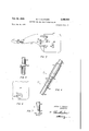
- Figure 4- is an enlarged detail of-the joint in the support for the free end of the arm for the chair;
- Figure 5 is an enlarged detail of the lower end of the support and showing that fits into a hole in the chair seat;
- Figure filis'a top planzview showing a detail of the corner of the chair seat having the-hole therein for receptionof the lower endof the-sup;- porting rod shown-in Figure'B; I
- Figure '7 is anelevationshowing adetail of'the forkedjoint between the upper and lower portions of.the supporting rodiforthe freeend-of the arm ofthechair, taken. a1ong;;line 1-1 in Figure4;
- Figure 8. is aview showing .the arm in folded position ready for a nesting in the seat of the chair.;.
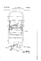
- Figure 9 is a ir'ontelevation of the chair in collapsed position,. and showing the folded armin 'nestedcposition;
- Figure 10 isa side elevation of a modified form of. arm which is not collapsible, thatis, itis'. not formed into two sections with hinges connecting the two sections together;
- Figure 11 is abottom plan. viewof'the form. of rigid arm shown in Figure. 10..
- the numeral Ill indicates thezbowedupper'portion of the. main frame of the. chair, having a back portion ll secured'th'erein, and thisbowed upper portion has integral. therewith legs 13 and I4. Thelowerend of, these legs l3' and lLare joined together-bya suitablerod' I54. 1
- tional foldable chair preferably made of suitable metal. It is my purpose to convert this chair into an arm chair by providing a collapsible foldable arm adapted to be removably secured to the conventional collapsible chair.
- I provide a bayonet slot 31 into which a ball 38 on a member 39 is fitted into the upper *enlarged portion and adapted to be pressed downinto the lower restricted portion to confine the same.
- This member 39 is suitably secured by welding or otherwise to an arm memher 4 I, which has pivoted thereto another portion 42 as by means of suitable hinges '43 and 44, these sections 4! and 42 being foldable along the line 45.
- I mount a guide. and support 45 in which a slidabie bar 41 is mounted for sliding movement.
- the bar 41 is forked asat 48 and adapted to fit over a pin 49 on the lower surface portions 4
- a rod 56 Whose lower end is .flattened'ia'nd renters into forked portion 51 of another rod 58, and the portions 56 ,and 58; arepivotally. securedlto each other'by means of a pivot pin, 591
- slidable cuff 60 is provided on rod 58, which is adapted to slide down overthe pivot point 59, and be arrested by a pin ,62 disposed in rod-58' tomake the joint between the rods 55 and 58 a'rigid connection.
- the chair .seatzl has therein a hole 65, into which the lower end of rod 58 is adapted to fit.
- This rod 58 has a shoulder 66 adapted to rest on a raised rim 6'! surrounding the hole 65.
- raised rim 'S'L has a depression 68' therein, into which a pin ,6 8 .ont he lower end of rod 58 is adapted to restto prevent turning of rod 58 in theho1e65.-
- a collapsible chair having a main frame and rear legs pivotally secured to the main frame and a seat member pivotally secured to the main frame and pivotally secured to the rear legs, a writing arm, a bayonet slot in the main frame, and a member mounted on the rear end of the arm and adapted to be releasably secured in the bayonet slot, a front corner of the seat member having a vertically disposed hole therein, a supporting arm pivotally secured to the front lower surface of the writing arm and having its lower end shaped to fit into the hole in the seat, the upper surface of the seat having a cavity extending from the wall of said hole, and a projection on the lower end of the supporting arm adapted to rest in said cavity for preventing rotative movement of the supporting arm.
- a collapsible chair having a mainframe and rear legs pivotally secured'to the main frame and a seat member pivotally secured to the main frame and pivotally secured to the rear legs, a writing arm, a bayonet slot in the main frame, a member mounted on the rear end of thefar'm'and adapted to be releasably secured inlthe' bayonet slot, a front corner of the seat member having" a vertically disposed hole therein, a supportingarm pivotally secured to the front lower surface of the writing arm.
- the writing arm being divided transversely into front and rear sections hingedly connected together so that the Writing arm can be folded and stowed beneath the seat portion.
- a collapsible chair having a main frame and rear legs pivotally secured to the main frame and a seat member pivotally secured to the main frame and pivotally secured to the rear legs, a writing arm, a bayonet slot in the mainframe, amember mounted on the rear end of the arm and adapted to be releasably secured in the bayonet slot, a front corner of the seat member having a vertically disposed hole therein, a supporting arm pivotally secured to the front lower sur- REFERENCES CITED
- the following references are of record inthe file of this patent:
Description
Oct. 26, 1948 w. T. CLAWSON WRITING ARM FOR COLLAPSIBLE CHAIRS 4 Sheets-Sheet 1 Filed May .15, 1946 William I 0/0 ws on INVENTOR.
0a. 26, 1948. w. T. CLAWSON 2,452,182
WRITING ARM FOR COLLAPSIBLE CHAIRS Filed May 15, 1946 4 Sheets-Sheet 2 FIG/6 William I Clawson' IN V EN T 0R.
Oct. 26, 1948. w. T. CLAWSON WRITING ARM FOR COLLAPSIBLE CHAIRS Filed May 15, 1946 4 Sheets-Sheet 3 FIG 9 William 7 Claws on Oct. 26, 1948. w T c Awso 2,452,182
WRITING ARM FOR COLLAPSIBLE CHAIRS File ad May l5,' 1946 v 4 Sheets-Sheet 4 FIG. /0
FIG.
W/l/am 7. Clan/son 3mm Patented Oct. 26, 1948 UNITE STA-IE3 "'F F 2,452,182
WRITING ARM'FOR COLL'APSIBLE CHAIRS.
William T; Clawson, Rock Hill; S: C. Application May 15, 1946, Serial No. 669,955.v
3 Claims.
,This invention: relates to a collapsible. chair Schools, aud'itoriums, and the like comprises a rigid non-collapsible chair having a rigid arm associated therewith for writing, and when it is necessary to transport these chairs from one building to another, as by placing them on a truck and hauling them from one location to another, only a very few of these chairs, compara- ,tively. speaking, .can be placedin a truck for transport, as. they fill upa great "amount, of. space.
'By providing a collapsible chair with-a removable or collapsible arm associatedtherewith, it
1s possible to remove the arm and to collapse the chair and to store or haul the. chairs and. arms inv a much smaller amount of space than would be the case where the arm isnot removable and the chair not collapsible. If desired, andvinone form'of the invention, it is shown,-the arm itself can be collapsed and folded or nested into the lower portion of the seat, where it will'be held in position and the entire assembly of chair and as a unit during transarm will be kept together port or storage.
It is, therefore, an object of thisinvention to provide a collapsible chair witha removable and collapsible arm, adapted to be nestedand-stowed inthe lower surface of the seat portion ofthe chair, so as to permit. a great numberof these chairs to be stacked within a very small space.
either for transport purposes or for storage purposes.
Itis another object ofthis invention to-provide I a collapsible. chair provided with aremovable arm so that the chair can be collapsed and. the arm can be removedlfor transport or storage purposes, thus resulting in the chair and arm occupying less than one-fourth'of. the space'whioh would be cccupied by the conventional rigid armchair.
Some of" the objects of the invention having been stated, other objects will'appear as the description proceeda'whentalien ir'rcormection with the accompanying drawingain which- Figure 1 is a top plan view of arcollapsiblechair ,equipped with my invention;
Figure. zis a side elevation ofFigure 1.;
Figure '3'is a bottom plan view-looking upwardly fromelong the. line. 3 3. in Figure 2 andshowfiri'gra portion ofthe chair in section;
Figure 4- is an enlarged detail of-the joint in the support for the free end of the arm for the chair; Figure 5 is an enlarged detail of the lower end of the support and showing that fits into a hole in the chair seat; v
Figure filis'a top planzview showing a detail of the corner of the chair seat having the-hole therein for receptionof the lower endof the-sup;- porting rod shown-in Figure'B; I
Figure '7 is anelevationshowing adetail of'the forkedjoint between the upper and lower portions of.the supporting rodiforthe freeend-of the arm ofthechair, taken. a1ong;;line 1-1 in Figure4;
Figure 8. is aview showing .the arm in folded position ready for a nesting in the seat of the chair.;.
Figure 9 is a ir'ontelevation of the chair in collapsed position,. and showing the folded armin 'nestedcposition;
Figure 10 'isa side elevation of a modified form of. arm which is not collapsible, thatis, itis'. not formed into two sections with hinges connecting the two sections together;
Figure 11 is abottom plan. viewof'the form. of rigid arm shown in Figure. 10.. I
x Referringv more specifically, to the drawings, the numeral Ill indicates thezbowedupper'portion of the. main frame of the. chair, having a back portion ll secured'th'erein, and thisbowed upper portion has integral. therewith legs 13 and I4. Thelowerend of, these legs l3' and lLare joined together-bya suitablerod' I54. 1
Secured to the legs i3.and,. M are cufi members and I8, which havepivotedthereto,as at l9, conventional rear legs .20 and; between which rods 2! and 22 are secured'for bracing these rear legs 20. .Secured to and spanningthe distance between the legs l3 and i4 is a..rod. 24'- ontwhich are pivotally mounted the intermediate; portions of strap iron-members. 25-and 26;. These strap. iron members. are :spot welded or. otherwise. secured ,to achairseat 2.1. The-rod.24-passessthrough the strap iron .members $25 and .26 and :forms .a pivot point for. the seat 21. The rearj endsof thestrap iron members 25 have enlarged portions :28: and 29 which are adapted torest against the cross rod v2|, when the chair is in erected position,
Pivotall-ysecured to the strap. iron members, 25 and 26, as at 32 and 33, are links and 31,,whose rear ends are secured, asaat 34, .to..-the. rear/leg 20'. The seat 2-! has .a downturned flange 35'extending around the-tedgesthereof, thus forming a pocket on-the underneatlrsurfaceeof the seat 2. 1. The use of this pocket will belater'referred to.
The structure thus far described is a convenportion, which .of the portion 42 for locking the 42 in parallel position.
tional foldable chair preferably made of suitable metal. It is my purpose to convert this chair into an arm chair by providing a collapsible foldable arm adapted to be removably secured to the conventional collapsible chair.
In the upper portion of leg 13, or if a left hand armchair is desired, the same can apply to the upper portion of leg M, I provide a bayonet slot 31 into which a ball 38 on a member 39 is fitted into the upper *enlarged portion and adapted to be pressed downinto the lower restricted portion to confine the same. This member 39 is suitably secured by welding or otherwise to an arm memher 4 I, which has pivoted thereto another portion 42 as by means of suitable hinges '43 and 44, these sections 4! and 42 being foldable along the line 45. On portion 4!, I mount a guide. and support 45 in which a slidabie bar 41 is mounted for sliding movement. The bar 41 is forked asat 48 and adapted to fit over a pin 49 on the lower surface portions 4| and Secured on the lower-surface 'of portion 42 is an inverted U-shapedbracket 53, having pivotally jsecuredthereto, as at 54, a-similar U-shaped bracket 55 to which is'secured. a rod 56, Whose lower end is .flattened'ia'nd renters into forked portion 51 of another rod 58, and the portions 56 ,and 58; arepivotally. securedlto each other'by means of a pivot pin, 591
v v v ,A slidable cuff 60 is provided on rod 58, which is adapted to slide down overthe pivot point 59, and be arrested by a pin ,62 disposed in rod-58' tomake the joint between the rods 55 and 58 a'rigid connection.
The chair .seatzl has therein a hole 65, into which the lower end of rod 58 is adapted to fit. This rod 58 has a shoulder 66 adapted to rest on a raised rim 6'! surrounding the hole 65. The
raised rim 'S'Lhas a depression 68' therein, into whicha pin ,6 8 .ont he lower end of rod 58 is adapted to restto prevent turning of rod 58 in theho1e65.-
In the 'modified'form of. the. invention, shown in Figures 10 and 1I,".like reference characters will but the a'rmis indicated as a piece and indicated at and'a shank' portjion. 13 adapted to fit into the hole 65 in the ,chair' 'seat. In' this form of the invention, the arm not be folded and nested in. the bottom of theichair seat, as in the other jform of the invention, would be transported or stored separatelyl When it is desired to collapse the chair and arm for transportior storage purposes, the arm, such .as shown in'Figures l0 and 11 can be removed from the chair and stored or transported separatelyand then the chair can be collapsed in'a conventional manner. However, if it is desired to keep the arm with the chair, then the collapsible armwould'be employed and this would be collapsed to the position, shown in Figure 8. It would then he slipped between the lower surface of the chair seat 21, and the transverse rod 24, which would wedge it in position and from whence it cannot be dislodged without being removed on In'the' drawings and specification, there has been set forth a preferred embodiment of the invention, and although specific terms have been employed, they'are used in a generic and descriptive sense only,and not for purposes of lim- 4 itation, the scope of the invention being defined in the claims.
I claim:
1. A collapsible chair having a main frame and rear legs pivotally secured to the main frame and a seat member pivotally secured to the main frame and pivotally secured to the rear legs, a writing arm, a bayonet slot in the main frame, and a member mounted on the rear end of the arm and adapted to be releasably secured in the bayonet slot, a front corner of the seat member having a vertically disposed hole therein, a supporting arm pivotally secured to the front lower surface of the writing arm and having its lower end shaped to fit into the hole in the seat, the upper surface of the seat having a cavity extending from the wall of said hole, and a projection on the lower end of the supporting arm adapted to rest in said cavity for preventing rotative movement of the supporting arm.
2. A collapsible chair having a mainframe and rear legs pivotally secured'to the main frame and a seat member pivotally secured to the main frame and pivotally secured to the rear legs, a writing arm, a bayonet slot in the main frame, a member mounted on the rear end of thefar'm'and adapted to be releasably secured inlthe' bayonet slot, a front corner of the seat member having" a vertically disposed hole therein, a supportingarm pivotally secured to the front lower surface of the writing arm. and having its lower end shaped to fit into the hole in the seat, means on the lower end of the supporting arm'for engaging said seat for preventing rotation of the supporting arm, the writing arm being divided transversely into front and rear sections hingedly connected together so that the Writing arm can be folded and stowed beneath the seat portion.
3. A collapsible chair having a main frame and rear legs pivotally secured to the main frame and a seat member pivotally secured to the main frame and pivotally secured to the rear legs, a writing arm, a bayonet slot in the mainframe, amember mounted on the rear end of the arm and adapted to be releasably secured in the bayonet slot, a front corner of the seat member having a vertically disposed hole therein, a supporting arm pivotally secured to the front lower sur- REFERENCES CITED The following references are of record inthe file of this patent:
UNITED STATES PATENTS Lochman 8i, al. July 21, 1936
Priority Applications (1)
| Application Number | Priority Date | Filing Date | Title |
|---|---|---|---|
| US669955A US2452182A (en) | 1946-05-15 | 1946-05-15 | Writing arm for collapsible chairs |
Applications Claiming Priority (1)
| Application Number | Priority Date | Filing Date | Title |
|---|---|---|---|
| US669955A US2452182A (en) | 1946-05-15 | 1946-05-15 | Writing arm for collapsible chairs |
Publications (1)
| Publication Number | Publication Date |
|---|---|
| US2452182A true US2452182A (en) | 1948-10-26 |
Family
ID=24688418
Family Applications (1)
| Application Number | Title | Priority Date | Filing Date |
|---|---|---|---|
| US669955A Expired - Lifetime US2452182A (en) | 1946-05-15 | 1946-05-15 | Writing arm for collapsible chairs |
Country Status (1)
| Country | Link |
|---|---|
| US (1) | US2452182A (en) |
Cited By (6)
| Publication number | Priority date | Publication date | Assignee | Title |
|---|---|---|---|---|
| US2676645A (en) * | 1952-05-16 | 1954-04-27 | Norcor Mfg Company Inc | Folding chair with tablet arm |
| US2711210A (en) * | 1955-06-21 | henrikson | ||
| US2717632A (en) * | 1952-10-09 | 1955-09-13 | Glenn B Morse | Folding tablet arm |
| US2719574A (en) * | 1953-02-24 | 1955-10-04 | Shwayder Brothers | Tablet arm chair |
| US2725924A (en) * | 1954-11-24 | 1955-12-06 | American Seating Co | Foldable tablet arm chair |
| US5649737A (en) * | 1995-11-03 | 1997-07-22 | Behnke; Fred E. | Chair tray |
Citations (7)
| Publication number | Priority date | Publication date | Assignee | Title |
|---|---|---|---|---|
| US125827A (en) * | 1872-04-16 | Improvement in revolving extension tables | ||
| US171528A (en) * | 1875-12-28 | Improvement in attaching book-supports to arm-chairs | ||
| US701728A (en) * | 1901-05-28 | 1902-06-03 | Samuel Madison Hudson | Chair. |
| US957552A (en) * | 1910-01-27 | 1910-05-10 | William R Gordon | Chair. |
| US1691053A (en) * | 1925-07-27 | 1928-11-13 | William S Ferris | Tablet armchair |
| US1744736A (en) * | 1928-10-25 | 1930-01-28 | Berman Samuel | Attachment for chairs |
| US2048014A (en) * | 1935-08-22 | 1936-07-21 | Clarin Mfg Co | Tablet arm for folding chairs |
-
1946
- 1946-05-15 US US669955A patent/US2452182A/en not_active Expired - Lifetime
Patent Citations (7)
| Publication number | Priority date | Publication date | Assignee | Title |
|---|---|---|---|---|
| US125827A (en) * | 1872-04-16 | Improvement in revolving extension tables | ||
| US171528A (en) * | 1875-12-28 | Improvement in attaching book-supports to arm-chairs | ||
| US701728A (en) * | 1901-05-28 | 1902-06-03 | Samuel Madison Hudson | Chair. |
| US957552A (en) * | 1910-01-27 | 1910-05-10 | William R Gordon | Chair. |
| US1691053A (en) * | 1925-07-27 | 1928-11-13 | William S Ferris | Tablet armchair |
| US1744736A (en) * | 1928-10-25 | 1930-01-28 | Berman Samuel | Attachment for chairs |
| US2048014A (en) * | 1935-08-22 | 1936-07-21 | Clarin Mfg Co | Tablet arm for folding chairs |
Cited By (6)
| Publication number | Priority date | Publication date | Assignee | Title |
|---|---|---|---|---|
| US2711210A (en) * | 1955-06-21 | henrikson | ||
| US2676645A (en) * | 1952-05-16 | 1954-04-27 | Norcor Mfg Company Inc | Folding chair with tablet arm |
| US2717632A (en) * | 1952-10-09 | 1955-09-13 | Glenn B Morse | Folding tablet arm |
| US2719574A (en) * | 1953-02-24 | 1955-10-04 | Shwayder Brothers | Tablet arm chair |
| US2725924A (en) * | 1954-11-24 | 1955-12-06 | American Seating Co | Foldable tablet arm chair |
| US5649737A (en) * | 1995-11-03 | 1997-07-22 | Behnke; Fred E. | Chair tray |
Similar Documents
| Publication | Publication Date | Title |
|---|---|---|
| US2731072A (en) | Portable walker, car seat and high chair combination | |
| US2611417A (en) | Mechanic's creeper | |
| US2587543A (en) | Portable foldable chair | |
| US2494199A (en) | Folding wheelbarrow | |
| US2452182A (en) | Writing arm for collapsible chairs | |
| US3193123A (en) | Utility truck | |
| US2170227A (en) | Collapsible baby carriage | |
| US1042193A (en) | Go-cart handle. | |
| US1152987A (en) | Folding extensible stool. | |
| US2177169A (en) | Bier | |
| US1367908A (en) | Collapsible table and chair | |
| US2788054A (en) | Collapsible baby walkers | |
| US2475797A (en) | Collapsible cart | |
| US2192672A (en) | Folding chair | |
| US1997767A (en) | Folding seat and back rest | |
| US2301640A (en) | Folding stroller | |
| US2233749A (en) | Chair | |
| US2781596A (en) | Collapsible crucifix | |
| US2738984A (en) | Collapsible shopping cart | |
| US989561A (en) | Perambulator. | |
| US1588575A (en) | Portable folding chair | |
| US2399861A (en) | Collapsible horse or support | |
| US1566178A (en) | Barrel or keg stand | |
| US1318195A (en) | Planoarai ll co | |
| US2551865A (en) | Hammock stand |