US2446292A - Insulated electrical conductor - Google Patents
Insulated electrical conductor Download PDFInfo
- Publication number
- US2446292A US2446292A US598310A US59831045A US2446292A US 2446292 A US2446292 A US 2446292A US 598310 A US598310 A US 598310A US 59831045 A US59831045 A US 59831045A US 2446292 A US2446292 A US 2446292A
- Authority
- US
- United States
- Prior art keywords
- conductor
- jacket
- glass
- layer
- insulated
- Prior art date
- Legal status (The legal status is an assumption and is not a legal conclusion. Google has not performed a legal analysis and makes no representation as to the accuracy of the status listed.)
- Expired - Lifetime
Links
- 239000004020 conductor Substances 0.000 title description 55
- 239000000463 material Substances 0.000 description 15
- 239000011521 glass Substances 0.000 description 14
- 239000004677 Nylon Substances 0.000 description 13
- 229920001778 nylon Polymers 0.000 description 13
- 239000011152 fibreglass Substances 0.000 description 12
- 229920001084 poly(chloroprene) Polymers 0.000 description 12
- 241000233866 Fungi Species 0.000 description 7
- LYCAIKOWRPUZTN-UHFFFAOYSA-N Ethylene glycol Chemical compound OCCO LYCAIKOWRPUZTN-UHFFFAOYSA-N 0.000 description 6
- 239000004816 latex Substances 0.000 description 6
- 229920000126 latex Polymers 0.000 description 6
- 239000002184 metal Substances 0.000 description 6
- 229910052751 metal Inorganic materials 0.000 description 6
- 238000010276 construction Methods 0.000 description 5
- 239000000835 fiber Substances 0.000 description 5
- 229920000742 Cotton Polymers 0.000 description 4
- 239000002904 solvent Substances 0.000 description 4
- 239000004753 textile Substances 0.000 description 4
- 229920000297 Rayon Polymers 0.000 description 3
- 238000005299 abrasion Methods 0.000 description 3
- 230000002542 deteriorative effect Effects 0.000 description 3
- 229920001971 elastomer Polymers 0.000 description 3
- 238000009413 insulation Methods 0.000 description 3
- 229920003023 plastic Polymers 0.000 description 3
- 239000004033 plastic Substances 0.000 description 3
- 239000002964 rayon Substances 0.000 description 3
- LFQSCWFLJHTTHZ-UHFFFAOYSA-N Ethanol Chemical compound CCO LFQSCWFLJHTTHZ-UHFFFAOYSA-N 0.000 description 2
- 239000004952 Polyamide Substances 0.000 description 2
- 239000010408 film Substances 0.000 description 2
- 239000003502 gasoline Substances 0.000 description 2
- 238000009434 installation Methods 0.000 description 2
- 239000011810 insulating material Substances 0.000 description 2
- 239000010687 lubricating oil Substances 0.000 description 2
- 229920002647 polyamide Polymers 0.000 description 2
- 150000003839 salts Chemical class 0.000 description 2
- 239000002966 varnish Substances 0.000 description 2
- XLYOFNOQVPJJNP-UHFFFAOYSA-N water Substances O XLYOFNOQVPJJNP-UHFFFAOYSA-N 0.000 description 2
- 229920000298 Cellophane Polymers 0.000 description 1
- RYGMFSIKBFXOCR-UHFFFAOYSA-N Copper Chemical compound [Cu] RYGMFSIKBFXOCR-UHFFFAOYSA-N 0.000 description 1
- 244000043261 Hevea brasiliensis Species 0.000 description 1
- 229920001800 Shellac Polymers 0.000 description 1
- 239000010425 asbestos Substances 0.000 description 1
- YACLQRRMGMJLJV-UHFFFAOYSA-N chloroprene Chemical group ClC(=C)C=C YACLQRRMGMJLJV-UHFFFAOYSA-N 0.000 description 1
- 239000011248 coating agent Substances 0.000 description 1
- 238000000576 coating method Methods 0.000 description 1
- 238000004040 coloring Methods 0.000 description 1
- 229910052802 copper Inorganic materials 0.000 description 1
- 239000010949 copper Substances 0.000 description 1
- 230000003292 diminished effect Effects 0.000 description 1
- 238000001125 extrusion Methods 0.000 description 1
- 229920002457 flexible plastic Polymers 0.000 description 1
- 239000012530 fluid Substances 0.000 description 1
- 239000013505 freshwater Substances 0.000 description 1
- 239000003365 glass fiber Substances 0.000 description 1
- 239000004519 grease Substances 0.000 description 1
- 239000004922 lacquer Substances 0.000 description 1
- 239000007788 liquid Substances 0.000 description 1
- 238000000034 method Methods 0.000 description 1
- 229920003052 natural elastomer Polymers 0.000 description 1
- 229920001194 natural rubber Polymers 0.000 description 1
- 229910052895 riebeckite Inorganic materials 0.000 description 1
- 239000004208 shellac Substances 0.000 description 1
- ZLGIYFNHBLSMPS-ATJNOEHPSA-N shellac Chemical compound OCCCCCC(O)C(O)CCCCCCCC(O)=O.C1C23[C@H](C(O)=O)CCC2[C@](C)(CO)[C@@H]1C(C(O)=O)=C[C@@H]3O ZLGIYFNHBLSMPS-ATJNOEHPSA-N 0.000 description 1
- 229940113147 shellac Drugs 0.000 description 1
- 235000013874 shellac Nutrition 0.000 description 1
- 239000007787 solid Substances 0.000 description 1
- 230000008961 swelling Effects 0.000 description 1
- 239000010409 thin film Substances 0.000 description 1
- 125000000391 vinyl group Chemical group [H]C([*])=C([H])[H] 0.000 description 1
- 239000012463 white pigment Substances 0.000 description 1
- 238000004804 winding Methods 0.000 description 1
Images
Classifications
-
- H—ELECTRICITY
- H01—ELECTRIC ELEMENTS
- H01B—CABLES; CONDUCTORS; INSULATORS; SELECTION OF MATERIALS FOR THEIR CONDUCTIVE, INSULATING OR DIELECTRIC PROPERTIES
- H01B7/00—Insulated conductors or cables characterised by their form
- H01B7/17—Protection against damage caused by external factors, e.g. sheaths or armouring
- H01B7/29—Protection against damage caused by extremes of temperature or by flame
Definitions
- This invention relates to an insulated electrical conductor that is so constructed that it has an exceptionally small over-all diameter and light Vweight for its service conditions.
- the present insulated electrical conductor may be used in many kinds of services but because of its light weight, small size and resistance to fire, solvents and the deteriorating effects of fungus, it is particularly well adapted for use in the wiring of aircraft.
- One object of the present invention is to provide an insulated conductor that is highly resistant to an external flame and to internal heat from' an over-loaded conductor.
- Another object is to provide an insulated conductor, that is lighter in weight and smaller in over-all diameter than the insulated conductors 'available heretofore for use in wiring aircraft.
- Another object is to provide an insulated con ductor which will render satisfactory service under an extremely wide range of high and low temperatures and is capable of withstanding repeated cycles of high heat and extreme cold.
- Another object is to provide an insulated conductor which is highly resistant to fungi, by selecting materials which are immune to fungi, or by completely enclosing any material subject to such attack with other resistant covering material.
- Another object is to provide an insulated conductor which is highly resistant to the deteriorating influence of solvents such as gasoline, lubricating oil, ethylene glycol, fluids used in hydraulic systems, and fresh and salt water.
- Another object is to provide an insulated conductor that is highly fiexible and has a tough smooth finish which together with its small diameter facilitates its installation.
- Another object is to provide an insulated conductor which is so constructed that the insulation can be easily and quickly pushed back adjacent an end of the metal conductor to expose a short end portion of the bare conductor, without damaging or nicking the conductor. This permits an end of the conductor to be quickly exposed so that it can be soldered or otherwise attached to a terminal.
- Another object is to provide an insulated conductor having a light color and smooth finish that will remain clean and thus facilitate identification of circuit markings printed or stenciled on the surface.
- Another object is to provide an insulated electrical conductor that makes more effective use of the dielectric properties of fibre glass.
- nbre glass has been used as an outer braid or covering because of its fire resisting qualities.
- the insulated electrical conductor of the present invention may have a solid or stranded conductor, around which is placed one or more layers of fire and fungi resistant non-adhering material, such as a serving or wrapping, a tape, or a braid formed of non-combustible fibers such as fiber glass or asbestos.
- This serving is laid directly upon the metal conductor and can be slid appreciably thereon to expose a short end portion of the conductor when desired.
- an insulating material forming an elastic jacket that has good resistance to moisture.
- the insulating jacket is preferably formed of polychloroprene latex (neoprene latex) which has good flame and fungi resistant properties, but may be formed of natural rubber or other rubber or rubber-like materials including the vinyl derivatives that are compounded to give them elastic properties.
- the fiber glass layer is likely to have minute fibers extending radially from the surface thereof, it is desirable to cause these minute fibers to be held down before the plastic jacket is applied, in order to secure a maximum degree of dielectric strength from a minimum wall thickness of the plastic jacket.
- This may be done by applying a thin film of varnish or lacquer over the fiber glass before or after it is applied as a layer.
- Better results however are obtained by wrapping a layer of textile fibers such as cotton, rayon or nylon over the fiber glass layer, or by winding a thin tape of flexible plastic material such as Cellophane over the fiber glass.
- the elastic jacket when formed of neoprene latex is preferably applied by the liquid-dipped method to insure that the coating will be disposed concentric to the metal conductor.
- a good practical form of apparatus for applying this latex jacket is disclosed in the Bartlett Patent No. 2,353,987 for Liquid applicator.
- the insulating jacket may be applied by extrusion,
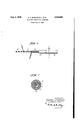
- Fig. 1 is a side elevation of an insulated electrical conductor constructed in accordance with the present invention and showing each insulating layer partly removed;
- Fig. 2 is an enlarged transverse sectional view taken on the line 2-2 of Fig. l.
- the conductor it may be formed of a single wire but is -preferably formed of a number of strands of annealed copper and these strands are preferably tinned, as this will give a protruding bare end portion of the wire added protection and facilitate soldered connections.
- a serving il of non-combustible material This serving is preferably fformed of a number of parallel illaments or strands of ll-bre glass and is wound tightly around the conductor l@ but is not adhesively secured thereto, so that the serving may be slid back a short distance from an end of the wire l@ when it is desired to expose a short end por tion of the wire so that it can be secured to a contact member.
- ne glass lbres are likely to protrude from the surface of the nbre glass layer il and if it is attempted to deposit an inE sulating material such as neoprene as a jaclret dlre'ctly over the layer il, these protruding fibres will extend into such jacket and reduce its dielectric strength.
- 'lhis dimculty may be overcome by applying a film of varnish or shellac over the layer il or to the liber glass before or after it is wound upon the conductor, but this makes it more diillcult to slip the layer li by a sliding movement back from an end of the oonductor it.
- this second layer may be wound in the same direction as the first layer.
- the cotton or rayon may be treated with a fungi resistant material before or after it is applied to increase the protection of the electric conductor from fungi.
- This second layer i2 holds down and covers the protruding bres of the layer il and provides a satisfactory surface to 4 underlying serving to any appreciable extent but will be bonded fIr-mly thereto.
- the neoprene jacket I3 has deposited thereover a thin illm Il of a synthetic linear polyamide such as nylon.
- the nylon used for this purpose is preferably an alcohol soluble nylon such for example as is sold on the market under the designation of type 6B and which is made as defined by claim 8 of the patent to Brubaker et al., No. 2,285,009.
- This nylon solution is preferably applied over the neoprene jacket by employing the apparatus disclosed in the above cited Bartlett patent, as it is found that this causes the nylon illm to embrace the neoprene jacket tightly.
- the nylon which has high tensile strength appears to shrink about the jacket to hug it tightly.
- the alcohol used as a solvent for the nylon does not produce any harmful swelling of the neoprene.
- the nylon however may be otherwise applied. It may be desirable to add a white pigment or coloring matter to the nylon solution so as to give the finished insulated electric conductor any desired receive a jacket i3 of insulating rubber or other color which will facilitate identification of the same when installed.
- a white or light colored outer surface for the conductor affords the further advantage in that identification numbers printed or vstenciled thereupon will show up clearly.
- the jacket I3 when formed of neoprene latex will have excellent llame and moisture resisting properties and will be highly resistant to the deteriorating influences of solvents such as gasoline.
- solvents such as gasoline.
- a serving of fibrous textile material wound over the libre glass so as to hold down stray glass libres an elastic jacket formed of a homogeneous plastic having lgood resistance to iiame and moisture covering cellent abrasion, flame and moisture resisting all of which may be present at dverent times to Y conductor wires installed in an airplane. Furthermore neoprene is well adapted to withstand cold temperatures.
- the nylon illm Il has high tensile strength and provides the conductor with a tough, smooth outer surface of light color, so that the wire identiilcation numbers placed thereupon will show up clearly and will not be readily obscured by grease or dirt.
- All of the covers II, I2, I2 and Il are so formed and applied that they aiiord the conductor Il excellent protection and insulation for the total thickness of the insulating material, and produce a highly exible insulated conductor.
- the in- A sulating material is suiiiciently comprensible as a whole to be readily pushed back from an end of the conductor Il to expose a short end portion so that it can be secured to a tenninal. This makes the use of a mechanical stripping tool which is likely to nick or otherwise injure the conductor I0 unnecessary.
- An insulated electrical conductor having excellent abrasion, llame and moisture resisting properties comprising a metal conductor, a ribbon-like serving of n ber glass wound in short spirals about the conductor in direct mi.
- a metal conductor comprising a metal conductor, a ribbon-like serving of nbre glass wound in short spirals about the conductor in direct contact therewith but not bonded thereto, a serving of fibrous textile material wound over the bre glass so as to hold down stray glass fibres, a, jacket oi poly-chloroprene bonded to the textile serving, and a thin strong film of synthetic linear polyamide covering and snugly embracing said jacket and having an outside diameter that is less than twice the diameter of the bare metal conductor, whereby a well covered highly nexible conductor o1' excellent insulating properties is provided and the insulation adjacent an end can be readily slid back to expose a short portion of the conductor.
Landscapes
- Organic Insulating Materials (AREA)
- Insulated Conductors (AREA)
Description
Aug 3, 1948. E. s. MccoNNELL. ETAL 2,446,292
INSULATED ELECTRICAL CONDUCTOR Filed June 8, 194,5
ANENY Patented Aug. 3, 1948 INSULATED ELECTRICAL CONDUCTOR Edmond s. McConnell, Scarborough, N. Y., and
Wlnfred K. Prlestley, West Barringto n, and
Victor F. Volk, Bristol, 8.11., assignors to United States Rubber Company, New York, N. Y., a corporation of New Jersey Application June 8,1945, SerialV No. 598,310
This invention relates to an insulated electrical conductor that is so constructed that it has an exceptionally small over-all diameter and light Vweight for its service conditions.
The present insulated electrical conductor may be used in many kinds of services but because of its light weight, small size and resistance to fire, solvents and the deteriorating effects of fungus, it is particularly well adapted for use in the wiring of aircraft.
One object of the present invention is to provide an insulated conductor that is highly resistant to an external flame and to internal heat from' an over-loaded conductor.
Another object is to provide an insulated conductor, that is lighter in weight and smaller in over-all diameter than the insulated conductors 'available heretofore for use in wiring aircraft.
Another object is to provide an insulated con ductor which will render satisfactory service under an extremely wide range of high and low temperatures and is capable of withstanding repeated cycles of high heat and extreme cold.
Another object is to provide an insulated conductor which is highly resistant to fungi, by selecting materials which are immune to fungi, or by completely enclosing any material subject to such attack with other resistant covering material.
Another object is to provide an insulated conductor which is highly resistant to the deteriorating influence of solvents such as gasoline, lubricating oil, ethylene glycol, fluids used in hydraulic systems, and fresh and salt water.
Another object is to provide an insulated conductor that is highly fiexible and has a tough smooth finish which together with its small diameter facilitates its installation.
Another object is to provide an insulated conductor which is so constructed that the insulation can be easily and quickly pushed back adjacent an end of the metal conductor to expose a short end portion of the bare conductor, without damaging or nicking the conductor. This permits an end of the conductor to be quickly exposed so that it can be soldered or otherwise attached to a terminal.
Another object is to provide an insulated conductor having a light color and smooth finish that will remain clean and thus facilitate identification of circuit markings printed or stenciled on the surface.
Another object is to provide an insulated electrical conductor that makes more effective use of the dielectric properties of fibre glass. Heretofore nbre glass has been used as an outer braid or covering because of its fire resisting qualities.
z Claims. (Cx. 114-120) However, fibre glass is very difficult to convert into a moisture resisting layer or covering and furthermore it has been found extremely susceptible to mechanical abrasion. In applying fibre glass next to the metallic conductor and subsequently covering it with an insulating and moisture resisting elastic jacket as herein disclosed it is no longer necessary to impregnate or moisture proof the insulating layer of fibre glass. Furthermore, by covering the metallic conductor with the fibers parallel as obtained by wrapping and serving. it is found that cutting and breaking of the glass and fibres is much diminished as compared with a braid wherein the fibres of glass cross over and under each other.
The insulated electrical conductor of the present invention may have a solid or stranded conductor, around which is placed one or more layers of fire and fungi resistant non-adhering material, such as a serving or wrapping, a tape, or a braid formed of non-combustible fibers such as fiber glass or asbestos. This serving is laid directly upon the metal conductor and can be slid appreciably thereon to expose a short end portion of the conductor when desired.
Over the fiber glass or other non-combustible layer is provided an insulating material forming an elastic jacket that has good resistance to moisture. The insulating jacket is preferably formed of polychloroprene latex (neoprene latex) which has good flame and fungi resistant properties, but may be formed of natural rubber or other rubber or rubber-like materials including the vinyl derivatives that are compounded to give them elastic properties.
However since the fiber glass layer is likely to have minute fibers extending radially from the surface thereof, it is desirable to cause these minute fibers to be held down before the plastic jacket is applied, in order to secure a maximum degree of dielectric strength from a minimum wall thickness of the plastic jacket. This may be done by applying a thin film of varnish or lacquer over the fiber glass before or after it is applied as a layer. Better results however are obtained by wrapping a layer of textile fibers such as cotton, rayon or nylon over the fiber glass layer, or by winding a thin tape of flexible plastic material such as Cellophane over the fiber glass.
The elastic jacket when formed of neoprene latex is preferably applied by the liquid-dipped method to insure that the coating will be disposed concentric to the metal conductor. A good practical form of apparatus for applying this latex jacket is disclosed in the Bartlett Patent No. 2,353,987 for Liquid applicator. However, the insulating jacket may be applied by extrusion,
'i'ollowing description when read in connection with the accompanying drawing illustrating one good practical embodiment of the invention. wherein:
Fig. 1 is a side elevation of an insulated electrical conductor constructed in accordance with the present invention and showing each insulating layer partly removed; and
Fig. 2 is an enlarged transverse sectional view taken on the line 2-2 of Fig. l.
The conductor it may be formed of a single wire but is -preferably formed of a number of strands of annealed copper and these strands are preferably tinned, as this will give a protruding bare end portion of the wire added protection and facilitate soldered connections. About the conductor i is wound a serving il of non-combustible material. This serving is preferably fformed of a number of parallel illaments or strands of ll-bre glass and is wound tightly around the conductor l@ but is not adhesively secured thereto, so that the serving may be slid back a short distance from an end of the wire l@ when it is desired to expose a short end por tion of the wire so that it can be secured to a contact member.
As above stated ne glass lbres are likely to protrude from the surface of the nbre glass layer il and if it is attempted to deposit an inE sulating material such as neoprene as a jaclret dlre'ctly over the layer il, these protruding fibres will extend into such jacket and reduce its dielectric strength. 'lhis dimculty may be overcome by applying a film of varnish or shellac over the layer il or to the liber glass before or after it is wound upon the conductor, but this makes it more diillcult to slip the layer li by a sliding movement back from an end of the oonductor it. Therefore a serving of cotton, rayon, nylon or other iibrous material is preferably wound over the layer il in the opposite direc= tion as shown in the drawing to form the second insulating layer i2. However this second layer may be wound in the same direction as the first layer. The cotton or rayon may be treated with a fungi resistant material before or after it is applied to increase the protection of the electric conductor from fungi. This second layer i2 holds down and covers the protruding bres of the layer il and provides a satisfactory surface to 4 underlying serving to any appreciable extent but will be bonded fIr-mly thereto.
It is desirable to provide the insulated electrical conductor of the present invention with a smoother and harder outer surface than is provided by neoprene. Therefore in accordance with the present invention the neoprene jacket I3 has deposited thereover a thin illm Il of a synthetic linear polyamide such as nylon. The nylon used for this purpose is preferably an alcohol soluble nylon such for example as is sold on the market under the designation of type 6B and which is made as defined by claim 8 of the patent to Brubaker et al., No. 2,285,009. This nylon solution is preferably applied over the neoprene jacket by employing the apparatus disclosed in the above cited Bartlett patent, as it is found that this causes the nylon illm to embrace the neoprene jacket tightly. The nylon which has high tensile strength appears to shrink about the jacket to hug it tightly. The alcohol used as a solvent for the nylon does not produce any harmful swelling of the neoprene. The nylon however may be otherwise applied. It may be desirable to add a white pigment or coloring matter to the nylon solution so as to give the finished insulated electric conductor any desired receive a jacket i3 of insulating rubber or other color which will facilitate identification of the same when installed. A white or light colored outer surface for the conductor affords the further advantage in that identification numbers printed or vstenciled thereupon will show up clearly.
is further disclosing the present invention. the following dimensions are given of one good practical construction that is now being manufactured for installation in aircrafts and which has an AN conductor size it, this being very nearly the same as A. W. G. size it.
@ver-all diameter Stranded conductor l0 .050 Fiber glass layer ll .055" Cotton layer i2 .,illiil'l Neoprene latex Jacket lll .089" Nylon nlm li .093"
Prior Commercial Constructi Present Construction on Size l Maximum Overall Weight lbs. Diam. 1000 it.
Weight lbs.
1 AN (Army-Na Conductor size which is ve near] the sem W. G. size. Vy) ry y o aan.
This table shows that the present construction is considerably smaller in diameter and lighter in weight than a representative prior construction that meets the same service conditions.
By employing a ilber glass layer II that is wound next to the conductor Il but is not adhesively secured thereto a lighter and more ilexible construction is secured than when the liber glass layer is impregnated with a bonding material. Furthermoreif all the other layers I 2, I2 and Il are destroyed by re the fiber glass layer II may still serve to insulate the conductor Il.
'I'he fibrous cover Il, as above stated, prevents ilbers from the cover II from entering the Jacket I3. It also increases the insulating properties of the covering materials, and it is protected from moisture by the jacket I3;
The jacket I3 when formed of neoprene latex will have excellent llame and moisture resisting properties and will be highly resistant to the deteriorating influences of solvents such as gasoline. lubricating oil, ethylene glycol, uids used in hydraulic systems, fresh water and salt water,
therewith but not bonded thereto, a serving of fibrous textile material wound over the libre glass so as to hold down stray glass libres, an elastic jacket formed of a homogeneous plastic having lgood resistance to iiame and moisture covering cellent abrasion, flame and moisture resisting all of which may be present at diilerent times to Y conductor wires installed in an airplane. Furthermore neoprene is well adapted to withstand cold temperatures.
The nylon illm Il has high tensile strength and provides the conductor with a tough, smooth outer surface of light color, so that the wire identiilcation numbers placed thereupon will show up clearly and will not be readily obscured by grease or dirt.
All of the covers II, I2, I2 and Il are so formed and applied that they aiiord the conductor Il excellent protection and insulation for the total thickness of the insulating material, and produce a highly exible insulated conductor. The in- A sulating material is suiiiciently comprensible as a whole to be readily pushed back from an end of the conductor Il to expose a short end portion so that it can be secured to a tenninal. This makes the use of a mechanical stripping tool which is likely to nick or otherwise injure the conductor I0 unnecessary.
Having thus described our invention, what we claim and desire to protect by Letters Patent is:
l. An insulated electrical conductor having excellent abrasion, llame and moisture resisting properties, comprising a metal conductor, a ribbon-like serving of n ber glass wound in short spirals about the conductor in direct mi.
properties, comprising a metal conductor, a ribbon-like serving of nbre glass wound in short spirals about the conductor in direct contact therewith but not bonded thereto, a serving of fibrous textile material wound over the bre glass so as to hold down stray glass fibres, a, jacket oi poly-chloroprene bonded to the textile serving, and a thin strong film of synthetic linear polyamide covering and snugly embracing said jacket and having an outside diameter that is less than twice the diameter of the bare metal conductor, whereby a well covered highly nexible conductor o1' excellent insulating properties is provided and the insulation adjacent an end can be readily slid back to expose a short portion of the conductor.
. EDMOND S. MQCONNELL. WINFRID K. ,PRIEB'I'IER VICTOR Il'. VOLK.
REFERENCES G'IED The following references are of record in the ille of` this patent:
UmmPATENTB Number Name Date 2,253,967 Carl et al Aug. 26, 1941 2,280,024 Hall et al Oct., 21, 1941 2.313,234 Gavitt Mar. 9, 1943 2,349,952 Fuller May 30, 1944 2,390,099 Slagter et al Nov. 27, 1945 FOREIGN PATENTE Number Country Date 565.354 Great Aw. 18. 1943
Priority Applications (1)
| Application Number | Priority Date | Filing Date | Title |
|---|---|---|---|
| US598310A US2446292A (en) | 1945-06-08 | 1945-06-08 | Insulated electrical conductor |
Applications Claiming Priority (1)
| Application Number | Priority Date | Filing Date | Title |
|---|---|---|---|
| US598310A US2446292A (en) | 1945-06-08 | 1945-06-08 | Insulated electrical conductor |
Publications (1)
| Publication Number | Publication Date |
|---|---|
| US2446292A true US2446292A (en) | 1948-08-03 |
Family
ID=24395056
Family Applications (1)
| Application Number | Title | Priority Date | Filing Date |
|---|---|---|---|
| US598310A Expired - Lifetime US2446292A (en) | 1945-06-08 | 1945-06-08 | Insulated electrical conductor |
Country Status (1)
| Country | Link |
|---|---|
| US (1) | US2446292A (en) |
Cited By (8)
| Publication number | Priority date | Publication date | Assignee | Title |
|---|---|---|---|---|
| US2540549A (en) * | 1948-04-22 | 1951-02-06 | Rotter Thcodore | Method of forming laminated articles |
| US2663755A (en) * | 1949-09-28 | 1953-12-22 | Plastic Wire & Cable Corp | Sheathed electric conductor |
| US2690984A (en) * | 1950-01-25 | 1954-10-05 | Gen Electric | Electric cable jacket |
| US2694601A (en) * | 1948-07-14 | 1954-11-16 | Tokheim Corp | Liquid dispensing device |
| US2723705A (en) * | 1950-07-21 | 1955-11-15 | Owens Corning Fiberglass Corp | Method and apparatus for making reinforced plastic laminates |
| US2759991A (en) * | 1951-01-26 | 1956-08-21 | Sandoz Ag | Insulated electrical conductors |
| US20060137897A1 (en) * | 2004-11-29 | 2006-06-29 | Grogl Dipl-Ing F | Electrical cable |
| US20100316229A1 (en) * | 2009-06-10 | 2010-12-16 | David Bibl | Electronic device accessories formed from intertwined fibers |
Citations (6)
| Publication number | Priority date | Publication date | Assignee | Title |
|---|---|---|---|---|
| US2253967A (en) * | 1938-08-02 | 1941-08-26 | Gen Electric | Insulated electrical conductor |
| US2260024A (en) * | 1938-09-01 | 1941-10-21 | Gen Electric | Insulated electrical conductor |
| US2313234A (en) * | 1940-09-14 | 1943-03-09 | Gavitt Mfg Company | Tinsel cord |
| GB555354A (en) * | 1941-05-21 | 1943-08-18 | Okonite Co | An improved insulated electric wire suitable for field telephone purposes |
| US2349952A (en) * | 1939-04-22 | 1944-05-30 | Bell Telephone Labor Inc | Electrical conductor |
| US2390039A (en) * | 1937-10-16 | 1945-11-27 | Owens Corning Fiberglass Corp | Insulated electrical conductor |
-
1945
- 1945-06-08 US US598310A patent/US2446292A/en not_active Expired - Lifetime
Patent Citations (6)
| Publication number | Priority date | Publication date | Assignee | Title |
|---|---|---|---|---|
| US2390039A (en) * | 1937-10-16 | 1945-11-27 | Owens Corning Fiberglass Corp | Insulated electrical conductor |
| US2253967A (en) * | 1938-08-02 | 1941-08-26 | Gen Electric | Insulated electrical conductor |
| US2260024A (en) * | 1938-09-01 | 1941-10-21 | Gen Electric | Insulated electrical conductor |
| US2349952A (en) * | 1939-04-22 | 1944-05-30 | Bell Telephone Labor Inc | Electrical conductor |
| US2313234A (en) * | 1940-09-14 | 1943-03-09 | Gavitt Mfg Company | Tinsel cord |
| GB555354A (en) * | 1941-05-21 | 1943-08-18 | Okonite Co | An improved insulated electric wire suitable for field telephone purposes |
Cited By (17)
| Publication number | Priority date | Publication date | Assignee | Title |
|---|---|---|---|---|
| US2540549A (en) * | 1948-04-22 | 1951-02-06 | Rotter Thcodore | Method of forming laminated articles |
| US2694601A (en) * | 1948-07-14 | 1954-11-16 | Tokheim Corp | Liquid dispensing device |
| US2663755A (en) * | 1949-09-28 | 1953-12-22 | Plastic Wire & Cable Corp | Sheathed electric conductor |
| US2690984A (en) * | 1950-01-25 | 1954-10-05 | Gen Electric | Electric cable jacket |
| US2723705A (en) * | 1950-07-21 | 1955-11-15 | Owens Corning Fiberglass Corp | Method and apparatus for making reinforced plastic laminates |
| US2759991A (en) * | 1951-01-26 | 1956-08-21 | Sandoz Ag | Insulated electrical conductors |
| US20060137897A1 (en) * | 2004-11-29 | 2006-06-29 | Grogl Dipl-Ing F | Electrical cable |
| US7297873B2 (en) * | 2004-11-29 | 2007-11-20 | Nexans | Electrical cable |
| US20100316229A1 (en) * | 2009-06-10 | 2010-12-16 | David Bibl | Electronic device accessories formed from intertwined fibers |
| US20100315299A1 (en) * | 2009-06-10 | 2010-12-16 | Apple Inc. | Fiber-based electronic device structures |
| CN102804811A (en) * | 2009-06-10 | 2012-11-28 | 苹果公司 | Electronic devices and electronic device accessories formed from interwoven fibers |
| CN102804811B (en) * | 2009-06-10 | 2015-08-12 | 苹果公司 | Electronic devices and electronic device accessories formed from interwoven fibers |
| US9154866B2 (en) | 2009-06-10 | 2015-10-06 | Apple Inc. | Fiber-based electronic device structures |
| US9628890B2 (en) * | 2009-06-10 | 2017-04-18 | Apple Inc. | Electronic device accessories formed from intertwined fibers |
| US10681447B2 (en) | 2009-06-10 | 2020-06-09 | Apple Inc. | Electronic device accessories formed from intertwined fibers |
| US11665461B2 (en) | 2009-06-10 | 2023-05-30 | Apple Inc. | Electronic device accessories formed from intertwined fibers |
| US12317023B2 (en) | 2009-06-10 | 2025-05-27 | Apple Inc. | Electronic device accessories formed from intertwined fibers |
Similar Documents
| Publication | Publication Date | Title |
|---|---|---|
| US2454625A (en) | Insulated electrical conductor and method of fabricating the same | |
| US1883269A (en) | Electrical conductor | |
| US3794750A (en) | Shielded cable | |
| CA1134920A (en) | Cable assembly for detecting the ingress of water inside a cable | |
| US3509269A (en) | Thermal barriers for cables | |
| US2446292A (en) | Insulated electrical conductor | |
| CS207705B2 (en) | Electric non-combustible connecting cable particularly for the transport vehicles and ships | |
| US3462544A (en) | Electrical conductors with a heat resistant electrical insulation system | |
| US3396231A (en) | Stress graded cable termination | |
| US2344501A (en) | Electric cable | |
| GB2213980A (en) | Electrical cable | |
| US2663752A (en) | Shielded electrical conductor with grounding strand | |
| US2631186A (en) | Conductor insulated with fused multiple layers | |
| US6087592A (en) | Enameled wire with high resistance to partial discharges | |
| US2140270A (en) | Electric cable | |
| US2677009A (en) | Shielded spark plug lead assembly | |
| US2469099A (en) | Electric windings and leads therefor | |
| GB625512A (en) | Improvements in electric cables | |
| US2485913A (en) | Electric condenser | |
| US2000095A (en) | Insulated electric conductor | |
| US2056017A (en) | High tension oil-filled cable | |
| US3626085A (en) | Cable termination housing having means for preventing corona and uniformly grading voltage | |
| US2388667A (en) | Electrical device | |
| US2120095A (en) | Insulated electrical cable | |
| JPS62160605A (en) | high voltage resistance wire |