US2444657A - Sewing machine - Google Patents
Sewing machine Download PDFInfo
- Publication number
- US2444657A US2444657A US558322A US55832244A US2444657A US 2444657 A US2444657 A US 2444657A US 558322 A US558322 A US 558322A US 55832244 A US55832244 A US 55832244A US 2444657 A US2444657 A US 2444657A
- Authority
- US
- United States
- Prior art keywords
- shafts
- bracket
- shaft
- housing
- feed
- Prior art date
- Legal status (The legal status is an assumption and is not a legal conclusion. Google has not performed a legal analysis and makes no representation as to the accuracy of the status listed.)
- Expired - Lifetime
Links
- 238000009958 sewing Methods 0.000 title description 35
- 230000007246 mechanism Effects 0.000 description 38
- 230000033001 locomotion Effects 0.000 description 34
- 230000003534 oscillatory effect Effects 0.000 description 11
- 239000000314 lubricant Substances 0.000 description 10
- 230000009471 action Effects 0.000 description 8
- 239000010687 lubricating oil Substances 0.000 description 6
- 230000006835 compression Effects 0.000 description 5
- 238000007906 compression Methods 0.000 description 5
- 230000008933 bodily movement Effects 0.000 description 4
- 239000004744 fabric Substances 0.000 description 4
- 238000005086 pumping Methods 0.000 description 4
- 238000010276 construction Methods 0.000 description 3
- 230000001050 lubricating effect Effects 0.000 description 3
- 239000000463 material Substances 0.000 description 3
- 230000010355 oscillation Effects 0.000 description 3
- 230000001105 regulatory effect Effects 0.000 description 3
- 238000006073 displacement reaction Methods 0.000 description 2
- 230000004048 modification Effects 0.000 description 2
- 238000012986 modification Methods 0.000 description 2
- 239000003921 oil Substances 0.000 description 2
- 230000004044 response Effects 0.000 description 2
- 241000726103 Atta Species 0.000 description 1
- NINIDFKCEFEMDL-UHFFFAOYSA-N Sulfur Chemical compound [S] NINIDFKCEFEMDL-UHFFFAOYSA-N 0.000 description 1
- 230000004075 alteration Effects 0.000 description 1
- 238000003491 array Methods 0.000 description 1
- CVXBEEMKQHEXEN-UHFFFAOYSA-N carbaryl Chemical compound C1=CC=C2C(OC(=O)NC)=CC=CC2=C1 CVXBEEMKQHEXEN-UHFFFAOYSA-N 0.000 description 1
- 230000000295 complement effect Effects 0.000 description 1
- 210000005069 ears Anatomy 0.000 description 1
- 230000008030 elimination Effects 0.000 description 1
- 238000003379 elimination reaction Methods 0.000 description 1
- 230000002093 peripheral effect Effects 0.000 description 1
- 230000000717 retained effect Effects 0.000 description 1
- 229920003051 synthetic elastomer Polymers 0.000 description 1
- 239000005061 synthetic rubber Substances 0.000 description 1
Images


Classifications
-
- D—TEXTILES; PAPER
- D05—SEWING; EMBROIDERING; TUFTING
- D05B—SEWING
- D05B27/00—Work-feeding means
- D05B27/10—Work-feeding means with rotary circular feed members
- D05B27/18—Feed cups
Definitions
- This invention relates to a sewin machine and more particularly to an improved sewing machine of the type having feed wheels rotatable about substantially parallel axes for supporting and feeding fabrics to the stitch-forming mechanism and generally known as a cup-feed sewing machine.
- An object of the invention is to provide amachine of the above type wherein the main drive shaft and the principal actuating mechanisms for the feed wheels are positioned above the feed wheels and are so arranged. as not to hinder or in any way obstruct the .operatorin the manipulation and handling of thefabric or fabrics being stitched.
- Another object of the invention is to provide a cup-feed type of sewing machine with a suitable and simple actuating mechanism including a vertically disposed main shaft and enclosed devices coupled to andoperated by the main shaft for imparting rotational movement to the feed wheels.
- the disposition of the main drive shaft vertically or parallel with the axes of the feed cups serves to simplify the connection with a motor or other suitable source of power.
- Another object of the invention is to provide a sewing machine of the character indicated above wherein the relative position of the outer feed wheel and the loop-taker of the stitch-forming mechanism is maintained under various operating conditions, such as different thicknesses of the work.
- Another object of the invention is to provide a cup-feed type of sewing machine having feed wheels so constructed and arranged that their axes of rotation remain substantially parallel irrespective of variations in thickness of the work being sewn.
- Another object of the invention is the provision of a cup-feed type of sewing machine having a reciprocating thread carrying needle that is adapted to cooperate with a complementary stitch-forming device mounted within oneof the wheels.
- Another object of the invention is to provide a machine of the above type so constructed as to permit coaxial operation of a thread manipulating element with one of the feed wheels within which it is disposed.
- a further object of the invention is the provision of a cup-feed sewing machine ofthe foregoing type whereinthe principal actuating devices are contained and supported'in a substana y oiht eh ho sin A stil u er biectoith nve t on side the provision of a lubricating system in which lubricant pumping or distributing means is responsive to movement of one of the feed wheels toward and away from the other for transmitting lubricant to the principal bearing .or relatively sliding surfaces of the actuating devices.
- the sewing machine of this invention comprises a housing consistin of an upstanding base having a laterally extending bracket.
- the housing may be adjustably suppOrt d 91, a vertical column by means of a suitable clamping and bracket arrangement,
- a pair of feed wheels constituting. an cuter feed wheel and an inner feed wheel, are atta'ehed toand rotatable with a pair of corresponding vertical shafts which are carried by and depend from the housing bracket.
- the axis of the shaft of the outer feed wheel is fixed, while th axis of the shaft of the inner feed wheel is movable about an axis that is substantially parallel to the .axes of both shafts, permitting movement of the inner feed wheel toward and away from the outer ieed wheel.
- Means are provided for normally and yieldingly moving the inner feed wheel toward the outer feed wheel, said feed wheels being maintained a predetermined minimum distance apart.
- Means are also provided for moving the inner feed wheel away from the outer feed wheel against the action of said yielding means.
- the feed wheels cooperate with a reciprocating thread carrying needle and a looper that is oscillatable aboutthe axis of the outer feed wheel for forming stitches in various fabrics.
- the actuating mechanism of this invention includes a Vertical main shaft which is coupled to and operates various driving devices supported within the housing.
- driving devices are suitable eccentrics, linkages, gearing, and a one-way clutch for operating the intermittent feed mechanism, all so constructed and arranged as to actuate the feed wheels, the reciprocating needle and the oscillatory looper in predetermined timed relation to the rotation of the main shaft.
- One of the features of this invention resides in the provision of a pumping system responsive to movement of the inner feed wheel, toward and away from the outer feed wheel, for transmitting lubricant to various devices within the hensing.
- the preferred and recommended time of pumping system contemplates a positivedisplacement pump wholl contained within the heusing andhaving at least a portionthereof dispesed in a sump or reservoir formed in the base portion of the housing. Lubricating oil or the like is transmitted by the pump through a discharge conduit and appropriate branch conduits to various mechanical connections within the housing, as will be readily understood from an examination of the drawings.
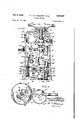
- Figure 1 is a side elevation of a machine embodying the invention.
- Figure 2 is a staggered vertical sectional view of the machine of Figure 1 with parts omitted;
- Figure 3 isa view of the illustrative machine, partly in top plan with the top cover plate removed and partly in horizontal section, certain parts being omitted;
- Figure 4 is a transverse vertical section taken along the broken line 4-4 of Figure 2;
- FIG. 5 is a detail view of the feed cups and related parts taken in horizontal section along line 5-5 of Figure 2;
- Figure 6 is a transverse sectional view taken along line 6-6 of Figure 3;
- the sewing machine 1 of this invention is illustrated in Figure 1 as being supported on a tubular cylindrical column H which carries a vertically adjustable bracket sleeve 12 that is provided with a lug l3 having a horizontalbore l4.
- Bracket sleeve I2 is vertically I slidable with respect to column H and may be adjustably secured thereto by set screws, not shown, or in any other manner known to the art.
- a supporting rod or bracket l5 extends through bore 14 in the lug and is secured thereto by means of a set screw 16.
- the housing of the sewing machine generally indicated by reference numeral I1, is provided with a lug is having a horizontal bore I9 extending therethrough for receiving supporting rod l5.
- a stop collar 20 is afilxed to supporting rod I 5 and serves to space housing I! from column H.
- a hand lever 22 is connected to and operates a locking device, the details of which are not shown, for securing lug Hi to rod l5.
- Sewing machine housing I! consists of an upstanding base 23 having a bottom wall 24 and side walls 25, which form an oil sump or reservoir in the bottom of the base, and a laterally projecting overhanging hollow arm or bracket 26.
- the housing is provided with a readily removable rear cover plate 21 anda top cover plate 28.
- a bearing support 29 is preferably formed integral with amass? overhanging bracket 26 at its outer end and projects downwardly therefrom.
- a substantially vertical main shaft 30 extends through the top of housing I1 and terminates at its upper end above said top and at its lower end within said housing.
- the lower end of shaft 36 is rotatable in a bearing sleeve or bushing 3
- a drive pulley 39 Attached to the upper end of shaft 30- by a set screw 38 is a drive pulley 39 which is secured to a hand wheel 40 by a screw 41 (Fig. 4).
- a V'-'loelt 42 (Fig. 1) cooperates with drive pulley 39 and delivers power thereto from an appropriate driving unit, not shown, for imparting rotation to main shaft 30.
- eccentric assembly 45 Mounted on shaft 30 and rotatable therewith is an eccentric assembly 45 that may be of the type disclosed in the patent to George Sauer, 2,189,656, granted February 6, 1940, and that includes an adjustable eccentric 46, a collar or eccentric operating or adjusting member 41, notched at 48, as best shown in Figure 3, and a spring pressed plunger 49.
- plunger 49 When it is desired to adjust eccentric 46, plunger 49 is pressed inwardly against the action of a compression spring 50 and hand wheel 46 is manually actuated to rotate shaft 3lluntil plunger 49 engages notch 48, whereupon further rotation of the hand wheel and shaft 30 will turn the latter with respect to eccentric 46.
- a connecting rod 5 I adjustable in length, carries at one end a strap 52 that embraces eccentric 46 and at its opposite end a second strap or split bearing 53 that surrounds a ball stud 54 connected to and rojecting upwardly from an arm 55 which extends laterally of a clutch mechanism generally designated by numeral 56.
- Clutch mechanism 56 is adapted to impart intermittent rotary movement in one direction to a vertical shaft 51 and may be of any type 'known to the art such as, for example, the type disclosed in the patent to W. B.
- ececntric 46 coacts with the strap of connecting rod 51 to impart oscillatory movement to arm 55, which oscillatory movement is translated into intermittent rotary movement of shaft 51 in one direction by clutch mechanism 56.
- a driving gear 58 having a hub 59 is secured to the upper end of shaft 51 by one or more set screws 60.
- meshing with driving gear 58 and having a corresponding hub 62 is secured by set screws 63 to the upper end :of a vertical shaft 64.
- Shaft 64 is rotatable in a pair of spaced bearings, namely, an upper sleeve or bushing 65 that is carried by a lug 66 projecting laterally within overhanging bracket 26, and a lower sleeve or hollow shaft 61 disposed within and extending below bearing support 29.
- Sleeve 61 is rotatable within bearing support'29 but is restrained from axial movement by a collar 68, secured thereto by set screws 69 and abuttingthe lower end of bearing support 29, and by a collar 10 clamped to ant-yea the upperend of sleeVeG'I and abutting the upper endof bearing support 29.
- Attached to the lower end of shaft 64 is a wheel II constituting the outer feed'wheel or feed cupof this invention and preferably'having its peripheral surface serrated or otherwise roughened.
- a split collar I2 is connected to the lower end of sleeve W by a clamp screw13,'asis best shown in Figures 5 and 10, and has a 'looper Ma'djusta'bly attached thereto by set screws I5;
- a radially adjustable needle guard I6 is also attached to collar I2 by a screw I I.
- An arm 89 projecting laterally from collar I9 and integral therewith is provided with an upwardly extending ball stud 8
- a connecting rod 82 adjustable in length, is provided at one end with a strap 83 that is'coupled to'ball stud BI and at its other end with a second strap 84 thatis “coupled to a ball stud 85'which is carried by a lever 89'.
- One end of 1ever8'9 pivotallyembraces a vertical hollow shaft 81 mounted in a pair of inwardly projecting lugs 98 and 99 integral with a wall of housin IT.
- a ball stud 99 projects upwardly from lever 99 intermediate its ends'and is coupled to a strap 9
- a bracket I92 (Figs. Zand 6) extending outwardly from the vertical portion of housing I! beneath bracket portion 28 is'p'rovided at its free end with a bore I93 that is coaxial with bore 98 in lug 99 and carriesa bearing sleeve-m4 within which the lower end 0f shaft 95 is "journ'aled.
- a swinging support'member generally denoted by numeral I95 is provided with a pair of parallel bores I99 and I9! and a flangeportion I98 forming the sidewall of a recess I 99'for housing meshin'g'g ears I-I9 and llI which are respectively attached to shaft 95 by setscrews H2, and a shaft H 3 by corresponding set screws 4; Bore I99 receives-aporti-on of the shaft 95 for rocking movement of the support about this shaft.
- the support is restrained against axial movement along'sh-aft 95 by bracket I92 and gear II9.
- a collar '5 is attached to shaft I I3 by set screws I Send cooperateswith gear I II to prevent axial movement of shaft II3 along bore I91.
- a wheel III constituting the second feed'wh'eel or feed cup of this invention is formed integral with'or otherwise attached to the lower end of shaft I I3 for rotation therewith and preferably has its-peri'pheral surfaceserrated-or otherwiseroughened. It will be noted that with the arrangement just described shafts 95 and H3 are both parallel to shaft 64.
- member I95 is rotatable about shaft 95' so thatinner feed wheelII'I may be swung toward or away from outer feedwheel- II, as desired; to permit the introduction amt-remover drwork snare-accommoda'te different thicknesses of wo'rkjthe various gears referred to' above remainingmmeshing'en g'agement, regardless of the relative position of feed wheel I I! with respect to feed wheel I I.
- This mechanism is best shown in Figure 2 and includes a stud head I29 that is screwed to one end of a horizontal pr esser bar I2I, slidable through a bearing sleeve I22 in the front wall of the housing and within an externally threaded regulating sleeve I23.
- Regulating sleeve I23 extends through a tapped lug I24 in the housing and is provided with a knurled adjusting head I25 at its outer end.
- Presser bar I2I has a collar I26 secured thereto by set'screws I21 and carries a concentric compression spring I28 that bears at one end against the collar'and at the other end against the inner end of regulating sleeve I23 for normally biasing stud head I29 toward the left as viewed in the drawings.
- the tension of spring I28 may be varied by'adjusting the sleeve I23.
- a stop screw I29 projects laterally of member I95 and cooperates with an adjustable stop screw I39 projecting laterally of bearing support 29 and having a lock-nut I3I.
- Feed wheel III may be manually moved away'from feed wheel II, against the action of stud head I29, presser bar I2I, and compression spring I28, by suitable means such as that shown in Figure 6.- This consists of a rod I92 threaded at one end I33 for connection with a tapped hole I39 in member I95 and-having a knob or handgrip I35 at its other end;
- a bell crank I39 having a vertical leg I31, formed with afoot I39 at its lower end bearing against an end surface of collar I29, and a horizontal leg I39 (Fig. '7)v Bell crank I36 is pivotally conneotedto a pin I99 that is maintained in a hollow lug I9! by a screw I92 (Fig.3).
- a connecting link I93 is pivoted to the free end of leg I39 by a screw Hi l-and is similarly connected by a screw M5 to apiston rod I49 of a reciprocating pump I47 that includes a casing I99 formed with a bracket M9 and that i'smounted on a side wall of the machine housing by screws I59 (Fig; 3).
- Pump I91 is positionedin thelowerportion of base 23'which, as was indicated earlier herein, constitutes a sumpor reservoir for lubricating oil.
- Bottom wall Z I'ofthe machine housing is provided witha threaded plug I5! which may be periodically removed for the purpose of draining the oilfrointhehousi'ng.
- the pump is provided with an inlet I54 having a check valve I55 and an outlet I56 having a check valve I51.
- pump inlet is preferably maintained below the 7 level of the lubricating oil inhousing I1 at all times and the pump is so constructed and arranged that upon upward movement of piston I52, in response to horizontal movement of presser bar I2I toward the right. as viewed in Figure 7, lubricating oil is admitted into the lower portion of the pump casing.
- lubricating oil previously admitted into the lower portion of the pump casing is discharged through outlet I56 and past discharge check valve I51 and into a discharge line I58.
- Lubricating oil so transmitted into discharge line 259 flows into a distribution conduit I59 that is provided with a plu- .such as a suitable synthetic rubber, and an external bearing ring 61 (Figs. 1, 4 and 8). Also communicating with dead end bore 63 is a sec- 0nd distribution conduit I68 that is provided with a removable plug I69at its left end and an overflow port I19, as viewed in Figures '1 and 8.
- Branch conduits I1I, I12, I13 and I14, communicating with and depending from distribution conduit I66, are also provided with wicking material I62 for transmitting oil to ball studs 96, 85, 54 and 8
- the stitch-forming devices of this invention include a needle I15 that is removably and adjustably secured to a reciprocatory tubular needle bar I16 by a set screw I11. Needle bar I15 is slidable through a, front bearing sleeve I18 that extends through a side wall of housing I1 and through a rear bearing sleeve I19 that is disposed in an upwardly projecting lug I86. A collar [BI is fastened to needle bar I15, intermediate the sleeves I18 and I19, by a plurality of set screws I82.
- Collar I8I is formed with a depending bifurcated member I83 which is slidable along parallel planar surfaces I94 of a guide bar I85 that is horizontally supported at opposite ends in the aforementioned lug I99 and a similar lug I86.
- FIG. 9 The modification of the machine of this invention illustrated in Figure 9 is generally similar to that shown in Figure 2, the difference residing in a slight alteration in the construction of housing I1 and in the elimination of lug I89.
- side wall I81 of Figure 9 i is bored at I88 to receive the rear bearing sleeve I19 for needle bar I16 and is also bored at 189 to receive and support an end of guide bar I85.
- a threaded cap I90 is screwed into bore I89 and is provided with a passage I 9
- Collar I8I is provided with a laterally projecting arm I94 that is coupled by a link I95 to one endof a lever I96 (Fig. 3) that is formed at its other end with an elongated collar I91 which is secured to a hollow shaft I98 by screws I99 (Fig.4).
- Shaft I98 is disposed substantially vertically and is mounted for rotation or rocking movement in a pair of bearing sleeves 269 and 2! that are retained in suitable openings in lugs 292 and 203, respectively, on the frame by corresponding set screws 294 and 205.
- a removable plug 296 in bottom wall 24 permits of ready access to shaft I99 and bearing 29L
- a pitman 201 is pivotally connected at one end to lever I96 by a pin 293, which extends through lever I96 and is aifixed thereto by a set screw 269, and at its otherend to a crank 2
- a bracket 2I5, secured to support 29 by screws 2I6, carries a throat plate 2I1 that is provided with an aperture 2I8 for the free passage of the end and shank portion of needle I15.
- a second bracket 2I9 is formed preferably integral with member I05, as shown, or, if desired, may be a separate unit rigidly attached to said member.
- a presser foot 22I Connected to bracket 2 I9 by screws 226 is a presser foot 22I having a needle-passage 222 (Fig. '1) that registers with aperture H8 in throat plate 2I1 (Fig. 10).
- Needle thread not shown, from a convenient source of supply, also not shown, is threaded through a guide 223, a thread tensioning device 224,9. second thread guide 225 (Figs. 1 and 8) and thence through the eye of the needle I15, in the order named.
- the machine of this invention is adapted to feed and form stitches in various materials for various purposes. It is particularly suited for the stitching of the closure portion 226 of abag 221 (Fig. 1).
- a housing comprising an upstanding base and a bracket extending laterally of said base, a feeding mechanism supported by said bracket and including a pair of substantially vertically arranged rotary shafts carried by and depending from said bracket, cooperating feed wheels attached to'the lower ends of said shfi fgtsandrneans ,for moving one of said shafts and the corresponding feed wheel about anaxis thatis substantially parallel to the axes of said sha t and a tua in m an o h me ine mechan sm n u n a ain haf an d c s, ope ated b s ma sha f im t rotation to the feed wheels.
- a usi om isin an u tandin base, and a b acket exte d nsl erally of said base, a feeding mechanism supportedbyv said bracket and including a pair of substantially vertically arranged rotary shafts. carried byand depending from said bracket, ,cooperating feedwheels attached to the lower ends of said shafts, and meansfor movingone ofsaid shafts and the corresponding feed wheel about an aXis that is substantiallyparallel to the axes of said; shafts,.and; actuating means for the feeding mechanism including a main shaft substantially parallel to said shafts. and havingat least a portion thereof disposed within said housing, and devices coupled to-and operated by. the portion of said mainshaft within. said housing for imparting .-rotation,to said feed wheels. 7
- a,housing comprising an upstandingbase and a-bracketextending lat.- erally of said base, a feeding mechanism, supported by said bracket and including apairof substantially vertically arranged rotary "shafts carried by-and depending from said bracket, cooperating feed wheels attached to thelower ends of said shafts,- andmeans fornormally and yieldingly urging oneof said shafts in a'directiontoward the other of said shafts about an axis-that is substantially parallel-to the axes of said shafts, and actuatingmeans for the feeding mechanism including a-main shaftand devices operated by said main shaft forimparting rotation to the feedwheels.
- a housing comprising an upstanding base and abracketextending laterally of saidba-se, a feeding mechanism supported by said bracket-and including a pair of substantially vertically arranged rotary shafts carried by and depending from said bracket, coopcrating-feed wheels attached tothe lower ends ofsaid shafts, and means for normallyand yieldingly urging one of said shafts in a-direction toward the other ,of said shafts about an axis that is substantially parallel to the axes-of said shafts, means for limiting movementof ,saidone of said shafts toward said othersof, said shafts to *rnaintain said feed wheels a predetermined minimum .distance apart, and actuating means for the feeding mechanism including a main shaftand-devices operated by said :main shaft for imparting rotation to the feed wheels.
- a housing comprising an upstanding base and a bracketextending laterally ,of said base, a feeding mechanism supportedby-said bracket and including a pair of substantially vertically arranged rotary shafts carried byand depending from said bracket, 00- operating feed-wheels attached to the lower ends of said shafts, andmeans for normally and yieldingly urging one of said shafts in a'direction toward theother of said shafts about an axis that is substantially parallel to the axes of said shafts, means for limitingmovement of'saidtone of said shafts toward said other vof said shafts to main- .tain said feed wheelsa predetermined minimum distance apart, means for moving said one.
- Paras d rec a s h .10 action of said first mentioned means, and actuating means including a'rotar-y main shaft substantially parallel to said shafts, a portion-of said main shaft extending through a wall of saidhcusing and terminating therein, and devices within said housing coupled to said main shaft and said feeding mechanism for imparting rotation to said feed wheels uponrotation of said-main-shaft.
- a housing comprising an upstanding base and abracket-extendingdaterally of said base, afeeding mechanism supported by said bracket and including substantiallyvertically, arranged rotary shafts carried by and depending from saidbracket and cooperating feed wheels attached to the -lower ends-- of said shafts and rotatabletherewith, saidsh-afts comprising a first shaft and a second shaft'intermediate said first shaft and saidbase and movable toward and away-from said firstshaf-t about an axis that is substantially parallelnto the axes of said shafts, cooperatingstitch forming devices located at one sidebf-saidbase and beneath said bracket and including a reciprocable needle and a looper adaptedwtoengagethe needle thread loop and oscillatable in an-arcuate path about the axis of one of said shafts, and actuating means including a main shaf-t' and'devices operated by said main shaft for imparting rotation to said feed wheels, reciprocatory movement
- a housing comprising an upstandin base and a bracket extendinglaterally of said base, a feedingv mechanism supported by said bracket and including a pair of substantially vertically arranged rotary shafts carried byanddepending from said bracket and cooperating feed wheels attached to the lower ends of said shafts, means for normally and yieldingly urging one of said shafts in a direction toward the other of said shafts about an.
- cooperating stitch-forming means including a reciprocatory needle and an oscillatory looper coaxial with one of said pair .of shafts adapted toengage the needle loop, and actuating means, including a main shaft and devices operated by said main haft for imparting rotation to said feed wheels, reciprocation to said needle, and oscillatory movement to said looper.
- a housing comprising an .lJpstanding base and a bracket extendingdaterally of said base, a feeding mechanism supis substantially parallel to the axes of said shafts.
- cooperating stitch-forming means including a reciprocatory needle and a looper adapted to engage the needle thread loop and oscillatable in an arcuate path and about an axis that is substantially normal to the path of reciprocation of said needle.
- actuating means including a main shaft and devices operated by said main shaft for imparting rotation to said feed wheels, reciprocation to said needle, and oscillatory movement to said looper.
- a housing comprisin an upstanding base and a bracket extending latorally of said base, a feeding mechanism supported 'by said bracket and including a pair of substantially vertically arranged rotary shafts carried by and depending from said bracket and cooperating feed wheels attached to the lower ends of said shafts, means for normally and yieldingly urging one of said shafts toward the other of said shafts about an axisthat is substantially parallel to the axes of said shafts, cooperating stitch-forming means including a re- 'ciprocatory needle and an oscillatory looper adapted to engage the needle loo and actuating means including a main shaft substantially parallel to said shafts and having at least a portion thereof disposed within the housing and devices coupled to and operated by the portion of said main shaft withinsaid housing for imparting rotation to said feed wheels, reciprocation to said needle, and oscillatory movement to said looper.
- a housing comprising an upstanding base and a bracket extending laterally of said base, a feeding mechanism supported by said bracket and including a pair of substantially vertically arranged rotary shafts carried by and depending from said bracket and. cooperating feed wheels attached to the lower ends of said shafts, means for normally and yieldingly urging one of said shafts in a direction toward the other of said shafts about an axis that is substantially parallel to the axes of said shafts, means for limiting movement of said one of said shafts towards said other of said shafts to maintain said feed wheels a predetermined minimum distance apart, cooperating titchforming means including a reciprocatory needle and a looper adapted to engage the needle thread loop and oscillatable in an arcuate path and about an axis that is substantially normal to the path of reciprocation of said needle, and actuating means including a main shaft substantially parallel to said shafts and having at least a portion thereof disposed within the housing and devices coupled to and operated by the portion of said main shaft within said housing for imparting rotation
- a housing comprising an upstanding base and a bracket extending latorally or said base, a feeding mechanism supported by said bracket and including a pair of substantially vertically arranged rotary shafts carried by and depending from said bracket and cooperating feed wheels attached to the lower ends of said shafts, one of said shafts being bodily movable toward and away from the other of said shafts, actuating means including a main shaft and devices operated by said main shaft for imparting rotation to said feed wheels, and means responsive to said bodily movement of said one of said shafts for supplying lubricant to said devices.
- a housing comprising an upstanding base and a bracket extending laterally of said base, a feeding mechanism supported by said bracket and including a pair of substantially vertically arranged rotary shafts carried by and depending from said bracket and cooperating feed wheels attached to the lower ends of said shafts, one of said shafts being bodily movable toward and away from the other of said shafts, actuating means including a main shaft substantially parallel to said shafts and having at least a portion thereof disposed within said housing and devices coupled to and operated by the portion of said main shaft within said housing for imparting rotation to said feed wheels, and means responsive to said bodily movement of said one of said shafts for supplying lubricant to said devices.
- a housing comprising an upstanding base and a bracket extending laterally of said base, a feeding mechanism supported by said bracket and including a pair of substantially vertically arranged rotary shafts carried by and depending from said bracket, cooperating feed wheels attached to the lower endsof said shafts, one of said shafts and its corresponding feed wheel being movable toward andaway from the other of said shafts and its corresponding feed wheel about an axis that is substantially parallel to the axes of said shafts, means normally and yieldingly urging said one of said shafts about said axis in a direction toward said other of said shafts, means for moving said one of said shafts in the opposite direction against the action of said means, actuating means including a main shaft and devices operated by said main shaft for imparting rotation to said feed wheels, and positive displacement pump means responsive to movement of said one of said shafts toward and away from said other of said shafts for supplying lubricant to said devices.
- a housing comprising an upstanding base and a bracket extending laterally of said base, a, feeding mechanism supported by said bracket and including a pair of substantially vertically arranged rotary shafts carried by and depending from said bracket and cooperating feed wheels attached to the lower ends of said shafts, one of said shafts being bodily movable toward and away from the other of said shafts, cooperating stitch-forming devices locatedat one side of the base and beneath the bracket and including a reciprocatory needle, and actuating means including a main shaft and devices operated by said main shaft for imparting rotation to said feed wheels and reciprocation to said needle, and pump means responsive to said bodily movement of said one of said shafts for supplyinglubricant to said devices.
- a housing comprising an upstanding base and a bracket extending laterally of said base, a feeding mechanism supported by said bracket and including apair of substantially vertically arranged rotary shafts carried by and depending from said bracket and cooperating feed wheels attached to the lower ends of said shafts, one of said shafts being bodily movable toward and away from the other of said shafts, cooperating stitch-forming devices located at one side of the base and beneath the bracket and including a reciprocatory needle and a looper adapted to engage the needle thread loop and oscillatable in an arcuate path about an axis that is substantially parallel to the axes of said shafts, and actuating means including a main shaft and devices operated by said main shaft for imparting rotation to said feed wheels, reciprocation to said needle and oscillation to said looper, and means responsive to said bodily movement of said one of said shafts for supplying lubricant to said devices.
- a housing comprising an upstanding base and a bracket extending laterally of said base, a feeding mechanism supported by said bracket and including a pair of substantially vertically arranged rotary shafts carried by and depending from said bracket and cooperating feed wheels attached to the lower ends of said shafts, means for moving one of said shafts and its corresponding feed wheel about an axis that is substantially parallel to the axes of said shafts, said means normally and yieldingly urging said one of said shafts in a direction toward said other of said shafts, means for moving said one of said shafts in the opposite direction against the action of said means, cooperating stitch-forming devices located at one side of the base and beneath the bracket and including a needle and a looper adapted to engage the needle thread loop and oscillatable in an arcuate path about an axis that is substantially parallel to the axes of said shafts, actuating means including a main shaft substantially parallel to said shafts and having at least a portion thereof disposed within said housing and devices within said housing and operated
- a hollow frame having a lubricant reservoir therein, stitch-forming devices and operating means therefor carried by said frame, work feeding means adapted to feed work in cooperative relation to said stitch-forming means, said work feeding means comprising a pair of feed wheels and operating means therefor, said feed wheels being relatively movable toward and from each other, a pump for distributing lubricant from said reservoir to said operating means, and means responsive to relative movement of said feed wheels toward and from each other for operating said pump.
- a housing comprising an upstanding base and a bracket extending laterally of said base, a feeding mechanism supported by said bracket and including a pair of substantially parallel vertically arranged rotary shafts carried by and depending from said bracket and cooperating feed wheels attached to the lower ends of said shafts and rotatable therewith, one of said shafts being movable toward and away from the other of said shafts about an axis parallel to the axes of said shafts, means for normally and yieldingly urging said one of said shafts toward the other of said shafts, means for moving said one of said shafts away from the other of said shafts against the action of said means, and actuating means for the feeding mechanism including a main shaft substantially parallel to said shafts, and devices coupled to said main shaft for imparting rotation to said feed Wheels.
- a housing comprising an upstanding base and a bracket extending laterally of said base, a feeding mechanism supported by said bracket and including a pair of substantially parallel vertically arranged rotary shafts carried by and depending from said bracket and cooperating feed wheels attached to the lower ends of said shafts and rotatable therewith, said pair of shafts consisting of a first shaft and a second shaft positioned between said first shaft and said base, means for effecting movement of said second shaft "and its corresponding feed wheel toward and away from said first shaft and its corresponding feed wheel while maintaining said shafts in parallel relationship, and actuating means including a rotary main shaft substantially parallel to said shafts, a portion of said main shaft extending through a wall of said housing and terminating therein, and devices within said housing coupled to said portion of said main shaft and said feeding mechanism for imparting rotation to said feed wheels upon rotation of said main shaft.
- a housing comprising an upstanding base and a bracket extending laterally of said base, a feeding mechanism supported by said bracket and including a pair of substantially parallel vertically arranged rotary shafts carried by and depending from said bracket and cooperating feed wheels attached to the lower ends of said shafts and rotatable therewith, said pair of shafts consisting of a first shaft and a second shaft positioned between said first shaft and said base, means for normally and yieldingly urging said second shaft in a direction toward said first shaft about an axis that is substantially parallel to the axes of said shafts, means for moving said second shaft in the opposite direction against the action of said means, cooperating stitch-forming devices located 'at one side of the base and beneath the bracket and including a needle reciprocatory in a plane substantially normal to the axes of said shafts, and actuating means including a main shaft substantially parallel to said shafts, and devices coupled to and operated by said main shaft for imparting rotation to said shafts and reciprocation to said needle.
Landscapes
- Engineering & Computer Science (AREA)
- Textile Engineering (AREA)
- Sewing Machines And Sewing (AREA)
Description
July 6, 194. H. J. LE VESCONTE ETAL 2,444,557
SEWING MACHINE '7 Sheets-Sheet 1 Filed Oct. 12, 1944 INVENTORS #420417 J1: l'sca/vr- ,H. J. LE VESCONTE ETAL July 6, 148;
SEWING MACHINE 7 Sheets-Sheet 2 Filed Oct. 12, 1944 Z WZ .y mm M WVS E m 1% J r w 25 A a x5 .mQ \w m% mu m\ MN \m Q mm ww N.
y 1948- r H. J. LEVESCONTE ETAL'" 2,444,657
SEWING MACHINE Filed Oct. 12,1944 7 Sheets-Sheet :s
PIE. /0
INVENTORS #9504012: kszs-co/vre' ATTqfA EY y 1943- H. J. LE VESCONTE ETAL. 2,444,657
SEWING MACHINE Filed Oct. 12, 1944' 7 Sheets-Sheet 5 BY JZBERT/ZSw/WEp/s' Arrays/Ex y 9 HJJ. LE VESCONTE ETAL 2,444,657 SEWING MACHINE Filed Oct. 12, 1944 7 Sheets-Sheet 7 11v VENTORS 61 9/9042? flsl-scawzz- A TIDE/YE Y Patented July 6 1948 UNITED STATES j; T ol ig.5-
SEWING MACHINE Harold J. Le Vesconte, Glendale, Calif., and Albert M. Schweda, Chicago, Ill., assignors to Union Special Machine Company, Chicago, Ill,
21 Claims.
This invention relates to a sewin machine and more particularly to an improved sewing machine of the type having feed wheels rotatable about substantially parallel axes for supporting and feeding fabrics to the stitch-forming mechanism and generally known as a cup-feed sewing machine.
An object of the invention is to provide amachine of the above type wherein the main drive shaft and the principal actuating mechanisms for the feed wheels are positioned above the feed wheels and are so arranged. as not to hinder or in any way obstruct the .operatorin the manipulation and handling of thefabric or fabrics being stitched.
Another object of the invention is to provide a cup-feed type of sewing machine with a suitable and simple actuating mechanism including a vertically disposed main shaft and enclosed devices coupled to andoperated by the main shaft for imparting rotational movement to the feed wheels. The disposition of the main drive shaft vertically or parallel with the axes of the feed cups serves to simplify the connection with a motor or other suitable source of power.
Another object of the invention is to provide a sewing machine of the character indicated above wherein the relative position of the outer feed wheel and the loop-taker of the stitch-forming mechanism is maintained under various operating conditions, such as different thicknesses of the work.
Another object of the invention is to provide a cup-feed type of sewing machine having feed wheels so constructed and arranged that their axes of rotation remain substantially parallel irrespective of variations in thickness of the work being sewn.
Another object of the invention is the provision of a cup-feed type of sewing machine having a reciprocating thread carrying needle that is adapted to cooperate with a complementary stitch-forming device mounted within oneof the wheels.
Another object of the invention is to provide a machine of the above type so constructed as to permit coaxial operation of a thread manipulating element with one of the feed wheels within which it is disposed.
A further object of the invention is the provision of a cup-feed sewing machine ofthe foregoing type whereinthe principal actuating devices are contained and supported'in a substana y oiht eh ho sin A stil u er biectoith nve t on side the provision of a lubricating system in which lubricant pumping or distributing means is responsive to movement of one of the feed wheels toward and away from the other for transmitting lubricant to the principal bearing .or relatively sliding surfaces of the actuating devices.
With the view of accomplishing the foregoing objects, the sewing machine of this invention comprises a housing consistin of an upstanding base having a laterally extending bracket. The housing may be adjustably suppOrt d 91, a vertical column by means of a suitable clamping and bracket arrangement,
A pair of feed wheels, constituting. an cuter feed wheel and an inner feed wheel, are atta'ehed toand rotatable with a pair of corresponding vertical shafts which are carried by and depend from the housing bracket. The axis of the shaft of the outer feed wheel is fixed, while th axis of the shaft of the inner feed wheel is movable about an axis that is substantially parallel to the .axes of both shafts, permitting movement of the inner feed wheel toward and away from the outer ieed wheel. Means are provided for normally and yieldingly moving the inner feed wheel toward the outer feed wheel, said feed wheels being maintained a predetermined minimum distance apart. Means, either manual or otherwise operable at will, are also provided for moving the inner feed wheel away from the outer feed wheel against the action of said yielding means. The feed wheels cooperate with a reciprocating thread carrying needle and a looper that is oscillatable aboutthe axis of the outer feed wheel for forming stitches in various fabrics.
The actuating mechanism of this invention includes a Vertical main shaft which is coupled to and operates various driving devices supported within the housing. Among the driving devices are suitable eccentrics, linkages, gearing, and a one-way clutch for operating the intermittent feed mechanism, all so constructed and arranged as to actuate the feed wheels, the reciprocating needle and the oscillatory looper in predetermined timed relation to the rotation of the main shaft.
One of the features of this invention resides in the provision of a pumping system responsive to movement of the inner feed wheel, toward and away from the outer feed wheel, for transmitting lubricant to various devices within the hensing. The preferred and recommended time of pumping system contemplates a positivedisplacement pump wholl contained within the heusing andhaving at least a portionthereof dispesed in a sump or reservoir formed in the base portion of the housing. Lubricating oil or the like is transmitted by the pump through a discharge conduit and appropriate branch conduits to various mechanical connections within the housing, as will be readily understood from an examination of the drawings.
The above enumerated objects and features, as well as others, together with the advantages attainable by the practice of this invention, will be readily apparent to persons skilled in the art upon reference to the following detailed description, taken in conjunction with the annexed drawings which respectively describe and illustrate a preferred embodiment of the invention and modifications thereof, and wherein:
Figure 1 is a side elevation of a machine embodying the invention; a
Figure 2 is a staggered vertical sectional view of the machine of Figure 1 with parts omitted;
Figure 3 isa view of the illustrative machine, partly in top plan with the top cover plate removed and partly in horizontal section, certain parts being omitted;
Figure 4 is a transverse vertical section taken along the broken line 4-4 of Figure 2;
Figure 5 is a detail view of the feed cups and related parts taken in horizontal section along line 5-5 of Figure 2;
Figure 6 is a transverse sectional view taken along line 6-6 of Figure 3;
"Figure 7 is a staggered vertical sectional view,
throughout the several views, the sewing machine 1 of this invention is illustrated in Figure 1 as being supported on a tubular cylindrical column H which carries a vertically adjustable bracket sleeve 12 that is provided with a lug l3 having a horizontalbore l4. Bracket sleeve I2 is vertically I slidable with respect to column H and may be adjustably secured thereto by set screws, not shown, or in any other manner known to the art.
A supporting rod or bracket l5 extends through bore 14 in the lug and is secured thereto by means of a set screw 16. The housing of the sewing machine, generally indicated by reference numeral I1, is provided with a lug is having a horizontal bore I9 extending therethrough for receiving supporting rod l5. A stop collar 20 is afilxed to supporting rod I 5 and serves to space housing I! from column H. A hand lever 22 is connected to and operates a locking device, the details of which are not shown, for securing lug Hi to rod l5.
Sewing machine housing I! consists of an upstanding base 23 having a bottom wall 24 and side walls 25, which form an oil sump or reservoir in the bottom of the base, and a laterally projecting overhanging hollow arm or bracket 26. The housing is provided with a readily removable rear cover plate 21 anda top cover plate 28. A bearing support 29 is preferably formed integral with amass? overhanging bracket 26 at its outer end and projects downwardly therefrom.
A substantially vertical main shaft 30 extends through the top of housing I1 and terminates at its upper end above said top and at its lower end within said housing. The lower end of shaft 36 is rotatable in a bearing sleeve or bushing 3| that is supported by a lug 32, while the upper Part of the shaft is rotatable in an upper bearing sleeve or bushing 33 that is carried by a removable plug 34 which is secured to the housing by screws 35 (Fig. 2). A pair of collars 36 and 31 secured to shaft .30 and abutting the upper end of sleeve bearing 3! and the lower end of sleeve bearing 33, respectively, restrain the shaft against axial movement. Attached to the upper end of shaft 30- by a set screw 38 is a drive pulley 39 which is secured to a hand wheel 40 by a screw 41 (Fig. 4). A V'-'loelt 42 (Fig. 1) cooperates with drive pulley 39 and delivers power thereto from an appropriate driving unit, not shown, for imparting rotation to main shaft 30.
Mounted on shaft 30 and rotatable therewith is an eccentric assembly 45 that may be of the type disclosed in the patent to George Sauer, 2,189,656, granted February 6, 1940, and that includes an adjustable eccentric 46, a collar or eccentric operating or adjusting member 41, notched at 48, as best shown in Figure 3, and a spring pressed plunger 49. When it is desired to adjust eccentric 46, plunger 49 is pressed inwardly against the action of a compression spring 50 and hand wheel 46 is manually actuated to rotate shaft 3lluntil plunger 49 engages notch 48, whereupon further rotation of the hand wheel and shaft 30 will turn the latter with respect to eccentric 46. This, due to the construction, will shift the eccentric diametrically one way or the other to increase or decrease its eccentricity with respect to the shaft as desired, and as is more fully explained in said Sauer patent. A connecting rod 5 I, adjustable in length, carries at one end a strap 52 that embraces eccentric 46 and at its opposite end a second strap or split bearing 53 that surrounds a ball stud 54 connected to and rojecting upwardly from an arm 55 which extends laterally of a clutch mechanism generally designated by numeral 56. Clutch mechanism 56 is adapted to impart intermittent rotary movement in one direction to a vertical shaft 51 and may be of any type 'known to the art such as, for example, the type disclosed in the patent to W. B. Long, et 211., 1,692,130, granted November 20, 1928. It is deemed sufficient for the purposes of this description to point out that upon rotation of main shaft 36, ececntric 46 coacts with the strap of connecting rod 51 to impart oscillatory movement to arm 55, which oscillatory movement is translated into intermittent rotary movement of shaft 51 in one direction by clutch mechanism 56. A driving gear 58 having a hub 59 is secured to the upper end of shaft 51 by one or more set screws 60.
A driven gear 6| meshing with driving gear 58 and having a corresponding hub 62 is secured by set screws 63 to the upper end :of a vertical shaft 64. Shaft 64 is rotatable in a pair of spaced bearings, namely, an upper sleeve or bushing 65 that is carried by a lug 66 projecting laterally within overhanging bracket 26, and a lower sleeve or hollow shaft 61 disposed within and extending below bearing support 29.
An arm 89 projecting laterally from collar I9 and integral therewith is provided with an upwardly extending ball stud 8| at its free end. A connecting rod 82, adjustable in length, is provided at one end with a strap 83 that is'coupled to'ball stud BI and at its other end with a second strap 84 thatis "coupled to a ball stud 85'which is carried by a lever 89'. One end of 1ever8'9 pivotallyembraces a vertical hollow shaft 81 mounted in a pair of inwardly projecting lugs 98 and 99 integral with a wall of housin IT. A ball stud 99 projects upwardly from lever 99 intermediate its ends'and is coupled to a strap 9| of a pitman 92that carries a second strap 93 which embraces an' eccentric 94' secured to shaft 39 and rotatable therewith.
From" the foregoing, taken in conjunction with Figures 2 and 3, it will be observed that upon rotation of shaft 39, oscillatory movement is imparted to sleeve 61 and thence to looper I l and needle guard I6 through the c-oaction of eccentric94; pitman 92, ball stud 99; lever 86; ball stud 85, connecting rod'82, ball stud 8|, arm 99, and collar I9, in the order named.
A shaft 95 parallel to shaft fi l'is mounted for rotation in a pair of spaced bearing sleeves 93 an'dQI'that are located in a bore 98 extending vertically through a lug 99 which projects upwardly from the bottom of frame bracket 29 (Fig. 6). A gear I99 that meshes with gear 58is attachedto the upper end of shaft 95 by set screws I9I. A bracket I92 (Figs. Zand 6) extending outwardly from the vertical portion of housing I! beneath bracket portion 28 is'p'rovided at its free end with a bore I93 that is coaxial with bore 98 in lug 99 and carriesa bearing sleeve-m4 within which the lower end 0f shaft 95 is "journ'aled.
I A swinging support'member generally denoted by numeral I95 is provided with a pair of parallel bores I99 and I9! and a flangeportion I98 forming the sidewall of a recess I 99'for housing meshin'g'g ears I-I9 and llI which are respectively attached to shaft 95 by setscrews H2, and a shaft H 3 by corresponding set screws 4; Bore I99 receives-aporti-on of the shaft 95 for rocking movement of the support about this shaft. The support is restrained against axial movement along'sh-aft 95 by bracket I92 and gear II9. A collar '5 is attached to shaft I I3 by set screws I Send cooperateswith gear I II to prevent axial movement of shaft II3 along bore I91. A wheel III constituting the second feed'wh'eel or feed cup of this invention is formed integral with'or otherwise attached to the lower end of shaft I I3 for rotation therewith and preferably has its-peri'pheral surfaceserrated-or otherwiseroughened. It will be noted that with the arrangement just described shafts 95 and H3 are both parallel to shaft 64. It will'be further noted that member I95 is rotatable about shaft 95' so thatinner feed wheelII'I may be swung toward or away from outer feedwheel- II, as desired; to permit the introduction amt-remover drwork snare-accommoda'te different thicknesses of wo'rkjthe various gears referred to' above remainingmmeshing'en g'agement, regardless of the relative position of feed wheel I I! with respect to feed wheel I I.
Member I is normally and yieldingly urged in a clockwise direction (Fig. 3) about the axis of shaft 95 so that feed wheel I I1 is yieldingly maintained in close proximity to feed wheel II (Figs. 2, 7 and 9) or in engagement with work between the two feed Wheels, by a mechanism that will now be described. This mechanism is best shown in Figure 2 and includes a stud head I29 that is screwed to one end of a horizontal pr esser bar I2I, slidable through a bearing sleeve I22 in the front wall of the housing and within an externally threaded regulating sleeve I23. Regulating sleeve I23 extends through a tapped lug I24 in the housing and is provided with a knurled adjusting head I25 at its outer end. Presser bar I2I has a collar I26 secured thereto by set'screws I21 and carries a concentric compression spring I28 that bears at one end against the collar'and at the other end against the inner end of regulating sleeve I23 for normally biasing stud head I29 toward the left as viewed in the drawings. The tension of spring I28 may be varied by'adjusting the sleeve I23. A stop screw I29 projects laterally of member I95 and cooperates with an adjustable stop screw I39 projecting laterally of bearing support 29 and having a lock-nut I3I. These stop screws serve to adjustably maintain the feed Wheels a predetermined minimum distance apart. Feed wheel III may be manually moved away'from feed wheel II, against the action of stud head I29, presser bar I2I, and compression spring I28, by suitable means such as that shown in Figure 6.- This consists of a rod I92 threaded at one end I33 for connection with a tapped hole I39 in member I95 and-having a knob or handgrip I35 at its other end;
It will be observed from an examination of the drawings, that fabrics are fedbetween and beyond feed wheels II and II! in the course of stitching the same, variations in thickness of-the work, due to seams and the like, will result in movement of feed wheel III toward and away from feed wheel 5 and corresponding movement of member I95 about the axis of shaft 95 to eiiect reciprocation of presser bar I2 I. Recip-rocation of presser bar I2! may also be attained, if desired, by manually actuating member I95 through the medium ofhandgrip I35'and rod I32; This reciprocation of bar I2! is utilized to actuate a pumping system for lubricating various devices contained within housing H. To thisend, we have provided a bell crank I39 having a vertical leg I31, formed with afoot I39 at its lower end bearing against an end surface of collar I29, and a horizontal leg I39 (Fig. '7)v Bell crank I36 is pivotally conneotedto a pin I99 that is maintained in a hollow lug I9! by a screw I92 (Fig.3). A connecting link I93 is pivoted to the free end of leg I39 by a screw Hi l-and is similarly connected by a screw M5 to apiston rod I49 of a reciprocating pump I47 that includes a casing I99 formed with a bracket M9 and that i'smounted on a side wall of the machine housing by screws I59 (Fig; 3). Pump I91 is positionedin thelowerportion of base 23'which, as was indicated earlier herein, constitutes a sumpor reservoir for lubricating oil.- Bottom wall Z I'ofthe machine housing is provided witha threaded plug I5! which may be periodically removed for the purpose of draining the oilfrointhehousi'ng. A
' piston 'l 523s Connected-lib the lowerenu'or pisten rod I46 and is normally biased in a downward direction by a compression spring I53 that is concentric with piston rod I46. The pump is provided with an inlet I54 having a check valve I55 and an outlet I56 having a check valve I51. The
pump inlet is preferably maintained below the 7 level of the lubricating oil inhousing I1 at all times and the pump is so constructed and arranged that upon upward movement of piston I52, in response to horizontal movement of presser bar I2I toward the right. as viewed in Figure 7, lubricating oil is admitted into the lower portion of the pump casing. Upon downward movement of piston I52 in response to horizontal movement of presser bar I2! toward the left, and due to the force of compression spring I53, lubricating oil previously admitted into the lower portion of the pump casing is discharged through outlet I56 and past discharge check valve I51 and into a discharge line I58. Lubricating oil so transmitted into discharge line 259 flows into a distribution conduit I59 that is provided with a plu- .such as a suitable synthetic rubber, and an external bearing ring 61 (Figs. 1, 4 and 8). Also communicating with dead end bore 63 is a sec- 0nd distribution conduit I68 that is provided with a removable plug I69at its left end and an overflow port I19, as viewed in Figures '1 and 8. Branch conduits I1I, I12, I13 and I14, communicating with and depending from distribution conduit I66, are also provided with wicking material I62 for transmitting oil to ball studs 96, 85, 54 and 8|, respectively, whereby these connections are properly lubricated. It will be apparent that distribution conduits I59 and I69 may be provided with additional branch conduits and wicking material for lubricating other connections within housing I1 as required.
The stitch-forming devices of this invention include a needle I15 that is removably and adjustably secured to a reciprocatory tubular needle bar I16 by a set screw I11. Needle bar I15 is slidable through a, front bearing sleeve I18 that extends through a side wall of housing I1 and through a rear bearing sleeve I19 that is disposed in an upwardly projecting lug I86. A collar [BI is fastened to needle bar I15, intermediate the sleeves I18 and I19, by a plurality of set screws I82. Collar I8I is formed with a depending bifurcated member I83 which is slidable along parallel planar surfaces I94 of a guide bar I85 that is horizontally supported at opposite ends in the aforementioned lug I99 and a similar lug I86.
The modification of the machine of this invention illustrated in Figure 9 is generally similar to that shown in Figure 2, the difference residing in a slight alteration in the construction of housing I1 and in the elimination of lug I89. It will be observed that side wall I81 of Figure 9 i is bored at I88 to receive the rear bearing sleeve I19 for needle bar I16 and is also bored at 189 to receive and support an end of guide bar I85. A threaded cap I90 is screwed into bore I89 and is provided with a passage I 9| that is coaxial with needle bar I16 to receive and protect the end thereof in the course of reciprocation during operation of the machine.
Reciprocation is imparted to collar I8I and therefore to needle bar I16 and needle I15 by devices which will now be described, with particular reference to Figures 2, 3 and 4. Collar I8I is provided with a laterally projecting arm I94 that is coupled by a link I95 to one endof a lever I96 (Fig. 3) that is formed at its other end with an elongated collar I91 which is secured to a hollow shaft I98 by screws I99 (Fig.4). Shaft I98 is disposed substantially vertically and is mounted for rotation or rocking movement in a pair of bearing sleeves 269 and 2! that are retained in suitable openings in lugs 292 and 203, respectively, on the frame by corresponding set screws 294 and 205. A removable plug 296 in bottom wall 24 permits of ready access to shaft I99 and bearing 29L A pitman 201 is pivotally connected at one end to lever I96 by a pin 293, which extends through lever I96 and is aifixed thereto by a set screw 269, and at its otherend to a crank 2| 9 which is secured to the lower end of drive shaft 39 by one or more set screws 2. With this arrangement rotation of main shaft 39 and crank 2H1 aotuates pitman 291 to eifect oscillation of lever I96 about hollow shaft I98 and reciprocation of collar I8I and needle bar I16 through the coaction of lever I96, link I95 and arm I94.
A bracket 2I5, secured to support 29 by screws 2I6, carries a throat plate 2I1 that is provided with an aperture 2I8 for the free passage of the end and shank portion of needle I15. A second bracket 2I9 is formed preferably integral with member I05, as shown, or, if desired, may be a separate unit rigidly attached to said member. Connected to bracket 2 I9 by screws 226 is a presser foot 22I having a needle-passage 222 (Fig. '1) that registers with aperture H8 in throat plate 2I1 (Fig. 10).
Needle thread, not shown, from a convenient source of supply, also not shown, is threaded through a guide 223, a thread tensioning device 224,9. second thread guide 225 (Figs. 1 and 8) and thence through the eye of the needle I15, in the order named. The machine of this invention is adapted to feed and form stitches in various materials for various purposes. It is particularly suited for the stitching of the closure portion 226 of abag 221 (Fig. 1).
From the foregoing it is believed that the construction, operation and advantages obtainable by the practice of our instant invention will be readily understood by persons skilled in the art.
. It is to be borne in mind, however, that various changes inthe apparatus herein illustrated and described may be resorted to without departing from the spirit of the invention or the scope of the subioined claims. For example, while a particularly simple and eiiective stitch-forming mechanism has been provided, in accordance with the invention, other types of such mechanism of known character, including one or more loop takers, might be substituted. A plurality of loopers, adapted to form an overedge type of stitch might be employed in conjunction with the other features of the invention.
We claim: 7
, L In a sewing machine, a housing comprising an upstanding base and a bracket extending laterally of said base, a feeding mechanism supported by said bracket and including a pair of substantially vertically arranged rotary shafts carried by and depending from said bracket, cooperating feed wheels attached to'the lower ends of said shfi fgtsandrneans ,for moving one of said shafts and the corresponding feed wheel about anaxis thatis substantially parallel to the axes of said sha t and a tua in m an o h me ine mechan sm n u n a ain haf an d c s, ope ated b s ma sha f im t rotation to the feed wheels.
2. In a ewine ma h n a usi om isin an u tandin base, and a b acket exte d nsl erally of said base, a feeding mechanism supportedbyv said bracket and including a pair of substantially vertically arranged rotary shafts. carried byand depending from said bracket, ,cooperating feedwheels attached to the lower ends of said shafts, and meansfor movingone ofsaid shafts and the corresponding feed wheel about an aXis that is substantiallyparallel to the axes of said; shafts,.and; actuating means for the feeding mechanism including a main shaft substantially parallel to said shafts. and havingat least a portion thereof disposed within said housing, and devices coupled to-and operated by. the portion of said mainshaft within. said housing for imparting .-rotation,to said feed wheels. 7
3. In asewing machine, a,housing comprising an upstandingbase and a-bracketextending lat.- erally of said base, a feeding mechanism, supported by said bracket and including apairof substantially vertically arranged rotary "shafts carried by-and depending from said bracket, cooperating feed wheels attached to thelower ends of said shafts,- andmeans fornormally and yieldingly urging oneof said shafts in a'directiontoward the other of said shafts about an axis-that is substantially parallel-to the axes of said shafts, and actuatingmeans for the feeding mechanism including a-main shaftand devices operated by said main shaft forimparting rotation to the feedwheels.
4, Ina -sewing-machine, .a housing comprising an upstanding base and abracketextending laterally of saidba-se, a feeding mechanism supported by said bracket-and including a pair of substantially vertically arranged rotary shafts carried by and depending from said bracket, coopcrating-feed wheels attached tothe lower ends ofsaid shafts, and means for normallyand yieldingly urging one of said shafts in a-direction toward the other ,of said shafts about an axis that is substantially parallel to the axes-of said shafts, means for limiting movementof ,saidone of said shafts toward said othersof, said shafts to *rnaintain said feed wheels a predetermined minimum .distance apart, and actuating means for the feeding mechanism including a main shaftand-devices operated by said :main shaft for imparting rotation to the feed wheels.
,5. In a sewingmachine, a housing comprising an upstanding base and a bracketextending laterally ,of said base,a feeding mechanism supportedby-said bracket and including a pair of substantially vertically arranged rotary shafts carried byand depending from said bracket, 00- operating feed-wheels attached to the lower ends of said shafts, andmeans for normally and yieldingly urging one of said shafts in a'direction toward theother of said shafts about an axis that is substantially parallel to the axes of said shafts, means for limitingmovement of'saidtone of said shafts toward said other vof said shafts to main- .tain said feed wheelsa predetermined minimum distance apart, means for moving said one. of sa d shaf the; Paras d rec a s h .10 action of said first mentioned means, and actuating means including a'rotar-y main shaft substantially parallel to said shafts, a portion-of said main shaft extending through a wall of saidhcusing and terminating therein, and devices within said housing coupled to said main shaft and said feeding mechanism for imparting rotation to said feed wheels uponrotation of said-main-shaft.
6. In a sewing machine, a housing comprising an upstanding base and abracket-extendingdaterally of said base, afeeding mechanism supported by said bracket and including substantiallyvertically, arranged rotary shafts carried by and depending from saidbracket and cooperating feed wheels attached to the -lower ends-- of said shafts and rotatabletherewith, saidsh-afts comprising a first shaft and a second shaft'intermediate said first shaft and saidbase and movable toward and away-from said firstshaf-t about an axis that is substantially parallelnto the axes of said shafts, cooperatingstitch forming devices located at one sidebf-saidbase and beneath said bracket and including a reciprocable needle and a looper adaptedwtoengagethe needle thread loop and oscillatable in an-arcuate path about the axis of one of said shafts, and actuating means including a main shaf-t' and'devices operated by said main shaft for imparting rotation to said feed wheels, reciprocatory movement to said needle and oscillatorymovement-to said looper.
7. In a sewing machine, a housing-comprising an upstandingbase and a bracket extending laterally of said base, afeeding mechanism-supported by said bracket and including substantially vertically arranged rotary shafts carried byv and depending from said bracket and cooperating feed wheels attached to the lower ends'of said shafts and rotatable therewith, said shafts comprising a first shaft and a second shaft intermediate said first shaft and said base, means for normally and yieldingly urging said second shaft in a:.direction toward said first shaft about an-axis that is substantially parallel to the'axes of said shafts, cooperating stitch-forming devices locatedto one side of said base and'beneath said-j bracket and including a reciprocatory needle and a looper adapted to engage the needle thread loop and oscillatable in an arc-uate path about the axis-of said first shaft, and actuating means-including a main shaft and devices operated by said main shaft for imparting rotation to said feed wheels, reciprocatory movement to said needle aud oscillatory movement to said looper.
8. In a sewing machine, a housing comprising an upstandin base and a bracket extendinglaterally of said base, a feedingv mechanism supported by said bracket and including a pair of substantially vertically arranged rotary shafts carried byanddepending from said bracket and cooperating feed wheels attached to the lower ends of said shafts, means for normally and yieldingly urging one of said shafts in a direction toward the other of said shafts about an. axis that is substantially parallel to the axesof said shafts, cooperating stitch-forming means including a reciprocatory needle and an oscillatory looper coaxial with one of said pair .of shafts adapted toengage the needle loop, and actuating means, including a main shaft and devices operated by said main haft for imparting rotation to said feed wheels, reciprocation to said needle, and oscillatory movement to said looper.
, 9,. In .a sewing machine, a housing comprising an .lJpstanding base and a bracket extendingdaterally of said base, a feeding mechanism supis substantially parallel to the axes of said shafts. 1
means forlimiting movement of said one of said shafts towards said other of said shafts to maintain said feed wheels a predetermined minimum distance apart, cooperating stitch-forming means including a reciprocatory needle and a looper adapted to engage the needle thread loop and oscillatable in an arcuate path and about an axis that is substantially normal to the path of reciprocation of said needle. and actuating means including a main shaft and devices operated by said main shaft for imparting rotation to said feed wheels, reciprocation to said needle, and oscillatory movement to said looper.
10. In a sewing machine. a housing comprisin an upstanding base and a bracket extending latorally of said base, a feeding mechanism supported 'by said bracket and including a pair of substantially vertically arranged rotary shafts carried by and depending from said bracket and cooperating feed wheels attached to the lower ends of said shafts, means for normally and yieldingly urging one of said shafts toward the other of said shafts about an axisthat is substantially parallel to the axes of said shafts, cooperating stitch-forming means including a re- 'ciprocatory needle and an oscillatory looper adapted to engage the needle loo and actuating means including a main shaft substantially parallel to said shafts and having at least a portion thereof disposed within the housing and devices coupled to and operated by the portion of said main shaft withinsaid housing for imparting rotation to said feed wheels, reciprocation to said needle, and oscillatory movement to said looper.
11. In a sewing machine, a housing comprising an upstanding base and a bracket extending laterally of said base, a feeding mechanism supported by said bracket and including a pair of substantially vertically arranged rotary shafts carried by and depending from said bracket and. cooperating feed wheels attached to the lower ends of said shafts, means for normally and yieldingly urging one of said shafts in a direction toward the other of said shafts about an axis that is substantially parallel to the axes of said shafts, means for limiting movement of said one of said shafts towards said other of said shafts to maintain said feed wheels a predetermined minimum distance apart, cooperating titchforming means including a reciprocatory needle and a looper adapted to engage the needle thread loop and oscillatable in an arcuate path and about an axis that is substantially normal to the path of reciprocation of said needle, and actuating means including a main shaft substantially parallel to said shafts and having at least a portion thereof disposed within the housing and devices coupled to and operated by the portion of said main shaft within said housing for imparting rotation to said feed wheels, reciprocation to said needle and oscillatory movement to said looper.
12. In a sewing machine, a housing comprising an upstanding base and a bracket extending latorally or said base, a feeding mechanism supported by said bracket and including a pair of substantially vertically arranged rotary shafts carried by and depending from said bracket and cooperating feed wheels attached to the lower ends of said shafts, one of said shafts being bodily movable toward and away from the other of said shafts, actuating means including a main shaft and devices operated by said main shaft for imparting rotation to said feed wheels, and means responsive to said bodily movement of said one of said shafts for supplying lubricant to said devices.
13. In a sewing machine, a housing comprising an upstanding base and a bracket extending laterally of said base, a feeding mechanism supported by said bracket and including a pair of substantially vertically arranged rotary shafts carried by and depending from said bracket and cooperating feed wheels attached to the lower ends of said shafts, one of said shafts being bodily movable toward and away from the other of said shafts, actuating means including a main shaft substantially parallel to said shafts and having at least a portion thereof disposed within said housing and devices coupled to and operated by the portion of said main shaft within said housing for imparting rotation to said feed wheels, and means responsive to said bodily movement of said one of said shafts for supplying lubricant to said devices.
14. In a sewing machine, a housing comprising an upstanding base and a bracket extending laterally of said base, a feeding mechanism supported by said bracket and including a pair of substantially vertically arranged rotary shafts carried by and depending from said bracket, cooperating feed wheels attached to the lower endsof said shafts, one of said shafts and its corresponding feed wheel being movable toward andaway from the other of said shafts and its corresponding feed wheel about an axis that is substantially parallel to the axes of said shafts, means normally and yieldingly urging said one of said shafts about said axis in a direction toward said other of said shafts, means for moving said one of said shafts in the opposite direction against the action of said means, actuating means including a main shaft and devices operated by said main shaft for imparting rotation to said feed wheels, and positive displacement pump means responsive to movement of said one of said shafts toward and away from said other of said shafts for supplying lubricant to said devices.
15. In a sewing machine, a housing comprising an upstanding base and a bracket extending laterally of said base, a, feeding mechanism supported by said bracket and including a pair of substantially vertically arranged rotary shafts carried by and depending from said bracket and cooperating feed wheels attached to the lower ends of said shafts, one of said shafts being bodily movable toward and away from the other of said shafts, cooperating stitch-forming devices locatedat one side of the base and beneath the bracket and including a reciprocatory needle, and actuating means including a main shaft and devices operated by said main shaft for imparting rotation to said feed wheels and reciprocation to said needle, and pump means responsive to said bodily movement of said one of said shafts for supplyinglubricant to said devices.
16. In a sewing machine, a housing comprising an upstanding base and a bracket extending laterally of said base, a feeding mechanism supported by said bracket and including apair of substantially vertically arranged rotary shafts carried by and depending from said bracket and cooperating feed wheels attached to the lower ends of said shafts, one of said shafts being bodily movable toward and away from the other of said shafts, cooperating stitch-forming devices located at one side of the base and beneath the bracket and including a reciprocatory needle and a looper adapted to engage the needle thread loop and oscillatable in an arcuate path about an axis that is substantially parallel to the axes of said shafts, and actuating means including a main shaft and devices operated by said main shaft for imparting rotation to said feed wheels, reciprocation to said needle and oscillation to said looper, and means responsive to said bodily movement of said one of said shafts for supplying lubricant to said devices.
1'7. In a sewing machine, a housing comprising an upstanding base and a bracket extending laterally of said base, a feeding mechanism supported by said bracket and including a pair of substantially vertically arranged rotary shafts carried by and depending from said bracket and cooperating feed wheels attached to the lower ends of said shafts, means for moving one of said shafts and its corresponding feed wheel about an axis that is substantially parallel to the axes of said shafts, said means normally and yieldingly urging said one of said shafts in a direction toward said other of said shafts, means for moving said one of said shafts in the opposite direction against the action of said means, cooperating stitch-forming devices located at one side of the base and beneath the bracket and including a needle and a looper adapted to engage the needle thread loop and oscillatable in an arcuate path about an axis that is substantially parallel to the axes of said shafts, actuating means including a main shaft substantially parallel to said shafts and having at least a portion thereof disposed within said housing and devices within said housing and operated by the portion of said main shaft within said housing for imparting rotation to said feed wheels and oscillation to said looper, and positive displacement pump means wholly within said housing and responsive to movement of said one of said shafts toward and away from said other of said shafts for supplying lubricant to said devices.
18. In a sewing machine a hollow frame having a lubricant reservoir therein, stitch-forming devices and operating means therefor carried by said frame, work feeding means adapted to feed work in cooperative relation to said stitch-forming means, said work feeding means comprising a pair of feed wheels and operating means therefor, said feed wheels being relatively movable toward and from each other, a pump for distributing lubricant from said reservoir to said operating means, and means responsive to relative movement of said feed wheels toward and from each other for operating said pump.
19. In a sewing machine, a housing comprising an upstanding base and a bracket extending laterally of said base, a feeding mechanism supported by said bracket and including a pair of substantially parallel vertically arranged rotary shafts carried by and depending from said bracket and cooperating feed wheels attached to the lower ends of said shafts and rotatable therewith, one of said shafts being movable toward and away from the other of said shafts about an axis parallel to the axes of said shafts, means for normally and yieldingly urging said one of said shafts toward the other of said shafts, means for moving said one of said shafts away from the other of said shafts against the action of said means, and actuating means for the feeding mechanism including a main shaft substantially parallel to said shafts, and devices coupled to said main shaft for imparting rotation to said feed Wheels.
20. In a sewing machine, a housing comprising an upstanding base and a bracket extending laterally of said base, a feeding mechanism supported by said bracket and including a pair of substantially parallel vertically arranged rotary shafts carried by and depending from said bracket and cooperating feed wheels attached to the lower ends of said shafts and rotatable therewith, said pair of shafts consisting of a first shaft and a second shaft positioned between said first shaft and said base, means for effecting movement of said second shaft "and its corresponding feed wheel toward and away from said first shaft and its corresponding feed wheel while maintaining said shafts in parallel relationship, and actuating means including a rotary main shaft substantially parallel to said shafts, a portion of said main shaft extending through a wall of said housing and terminating therein, and devices within said housing coupled to said portion of said main shaft and said feeding mechanism for imparting rotation to said feed wheels upon rotation of said main shaft.
21. In a sewing machine, a housing comprising an upstanding base and a bracket extending laterally of said base, a feeding mechanism supported by said bracket and including a pair of substantially parallel vertically arranged rotary shafts carried by and depending from said bracket and cooperating feed wheels attached to the lower ends of said shafts and rotatable therewith, said pair of shafts consisting of a first shaft and a second shaft positioned between said first shaft and said base, means for normally and yieldingly urging said second shaft in a direction toward said first shaft about an axis that is substantially parallel to the axes of said shafts, means for moving said second shaft in the opposite direction against the action of said means, cooperating stitch-forming devices located 'at one side of the base and beneath the bracket and including a needle reciprocatory in a plane substantially normal to the axes of said shafts, and actuating means including a main shaft substantially parallel to said shafts, and devices coupled to and operated by said main shaft for imparting rotation to said shafts and reciprocation to said needle.
HAROLD J. LE VESCONTE ALBERT M. SCHWEDA.
REFERENCES CITED The following references are of record in the file of this patent:
UNITED STATES PATENTS Number Name Date 180,225 Gullrandsen et al. July 25, 1876 I 2,043,737- Christensen June 9, 1936 FOREIGN PATENTS Number Country Date 58,991 Germany 1891
Priority Applications (1)
| Application Number | Priority Date | Filing Date | Title |
|---|---|---|---|
| US558322A US2444657A (en) | 1944-10-12 | 1944-10-12 | Sewing machine |
Applications Claiming Priority (1)
| Application Number | Priority Date | Filing Date | Title |
|---|---|---|---|
| US558322A US2444657A (en) | 1944-10-12 | 1944-10-12 | Sewing machine |
Publications (1)
| Publication Number | Publication Date |
|---|---|
| US2444657A true US2444657A (en) | 1948-07-06 |
Family
ID=24229094
Family Applications (1)
| Application Number | Title | Priority Date | Filing Date |
|---|---|---|---|
| US558322A Expired - Lifetime US2444657A (en) | 1944-10-12 | 1944-10-12 | Sewing machine |
Country Status (1)
| Country | Link |
|---|---|
| US (1) | US2444657A (en) |
Cited By (3)
| Publication number | Priority date | Publication date | Assignee | Title |
|---|---|---|---|---|
| US2518987A (en) * | 1945-07-09 | 1950-08-15 | Singer Mfg Co | Sewing machine |
| US2847955A (en) * | 1955-11-21 | 1958-08-19 | St Regis Paper Co | Bag closing apparatus |
| US4970977A (en) * | 1988-07-23 | 1990-11-20 | Union Special Gmbh | Portable, single-thread chain stitch, bag closing machine with a movable needle guiding device |
Citations (3)
| Publication number | Priority date | Publication date | Assignee | Title |
|---|---|---|---|---|
| DE58991C (en) * | E. WINCKELMANN in Berlin S., Grimmstr. 3 | Glove sewing machine | ||
| US180225A (en) * | 1876-07-25 | gullrandsen | ||
| US2043737A (en) * | 1935-12-18 | 1936-06-09 | Union Special Machine Co | Sewing machine |
-
1944
- 1944-10-12 US US558322A patent/US2444657A/en not_active Expired - Lifetime
Patent Citations (3)
| Publication number | Priority date | Publication date | Assignee | Title |
|---|---|---|---|---|
| DE58991C (en) * | E. WINCKELMANN in Berlin S., Grimmstr. 3 | Glove sewing machine | ||
| US180225A (en) * | 1876-07-25 | gullrandsen | ||
| US2043737A (en) * | 1935-12-18 | 1936-06-09 | Union Special Machine Co | Sewing machine |
Cited By (3)
| Publication number | Priority date | Publication date | Assignee | Title |
|---|---|---|---|---|
| US2518987A (en) * | 1945-07-09 | 1950-08-15 | Singer Mfg Co | Sewing machine |
| US2847955A (en) * | 1955-11-21 | 1958-08-19 | St Regis Paper Co | Bag closing apparatus |
| US4970977A (en) * | 1988-07-23 | 1990-11-20 | Union Special Gmbh | Portable, single-thread chain stitch, bag closing machine with a movable needle guiding device |
Similar Documents
| Publication | Publication Date | Title |
|---|---|---|
| US2266140A (en) | Chain-stitch sewing machine | |
| US2444657A (en) | Sewing machine | |
| US2238796A (en) | Overedge sewing machine | |
| US2636462A (en) | Overedge sewing machine | |
| GB998397A (en) | Improvements in or relating to chain-stitch sewing machines | |
| US2341448A (en) | Feeding mechanism for sewing machines | |
| USRE23224E (en) | Sewing machine | |
| US2329681A (en) | Needle-vibrating mechanism for sewing machines | |
| US2609770A (en) | Sewing machine | |
| GB1187725A (en) | Improvements in or relating to Sewing Machines | |
| US2312858A (en) | Chain-stitch sewing machine | |
| US2005673A (en) | Sewing machine | |
| GB1019727A (en) | Improvements in blindstitch sewing machines | |
| US3111918A (en) | Sewing machine for sewing hides and skins | |
| US2277971A (en) | Sewing machine | |
| GB448259A (en) | Improvements in sewing machines | |
| US2345327A (en) | Chain-stitch sewing machine | |
| US2973732A (en) | Sewing machines | |
| US2627829A (en) | Overedge sewing machine | |
| US3272164A (en) | Lubricating systems for sewing machines | |
| US2947270A (en) | Sewing machines | |
| US2145823A (en) | Peeding mechanism for sewing machines | |
| US2189656A (en) | Feed mechanism for sewing machines and the like | |
| US2670703A (en) | Sewing machine with puller drive | |
| US2851976A (en) | Sewing machines |