US2430529A - Manufacture of leaf springs - Google Patents
Manufacture of leaf springs Download PDFInfo
- Publication number
- US2430529A US2430529A US613776A US61377645A US2430529A US 2430529 A US2430529 A US 2430529A US 613776 A US613776 A US 613776A US 61377645 A US61377645 A US 61377645A US 2430529 A US2430529 A US 2430529A
- Authority
- US
- United States
- Prior art keywords
- workpiece
- vice
- anvil
- lug
- manufacture
- Prior art date
- Legal status (The legal status is an assumption and is not a legal conclusion. Google has not performed a legal analysis and makes no representation as to the accuracy of the status listed.)
- Expired - Lifetime
Links
- 238000004519 manufacturing process Methods 0.000 title description 7
- 210000003128 head Anatomy 0.000 description 7
- 238000005242 forging Methods 0.000 description 5
- 238000003825 pressing Methods 0.000 description 5
- 238000000034 method Methods 0.000 description 3
- 230000000694 effects Effects 0.000 description 2
- 238000010438 heat treatment Methods 0.000 description 2
- 239000002184 metal Substances 0.000 description 2
- 230000000717 retained effect Effects 0.000 description 2
- 241000600039 Chromis punctipinnis Species 0.000 description 1
- 206010011878 Deafness Diseases 0.000 description 1
- 229910000831 Steel Inorganic materials 0.000 description 1
- 238000005452 bending Methods 0.000 description 1
- 238000010276 construction Methods 0.000 description 1
- 210000000887 face Anatomy 0.000 description 1
- 238000003780 insertion Methods 0.000 description 1
- 230000037431 insertion Effects 0.000 description 1
- 229920000136 polysorbate Polymers 0.000 description 1
- 239000010959 steel Substances 0.000 description 1
- 230000008719 thickening Effects 0.000 description 1
Images


Classifications
-
- B—PERFORMING OPERATIONS; TRANSPORTING
- B21—MECHANICAL METAL-WORKING WITHOUT ESSENTIALLY REMOVING MATERIAL; PUNCHING METAL
- B21J—FORGING; HAMMERING; PRESSING METAL; RIVETING; FORGE FURNACES
- B21J9/00—Forging presses
- B21J9/02—Special design or construction
- B21J9/06—Swaging presses; Upsetting presses
- B21J9/08—Swaging presses; Upsetting presses equipped with devices for heating the work-piece
Definitions
- Leaf springs are frequently madewith a main oreupper leaf which, has forged eyes, at the end to receive ,a shackle; pin and the present inven-,
- tion relates to, the forging ;of 'theendsflof such;
- aprocess offorging.-.a leafspr-ingwith lugs atthe ends *of the leaiw for-shackle -pins-- comprises-the steps of gripping the deaf between-thejaws-pf a'vice electrode- S0 -that one end -of the leaf projectsz from the Jaws," causing this end'to abut against an anvil-electrode and 'thereby heating the'pcn tion between-the electrodes electrically, upsetting the heated end by endwise-pressureexertedbe:
- the vice jaws are formed so that-one of them is hollowed out where it would otherwise bear along the 'centreotthe-workpiece and has a bearing surface only, upon the side mar-- gins ,ofythe face while the other is shapedrto bear upon a central zone only,
- the hollowedout vvice jaw is the lower .one andrthep one which bears on the central, zone onlyis.-.,th,e:
- a further feature of the invention lies inpro-' viding theend'of -the-ram which engages the workpiece with a-hollowed"out portion shaped to fitthe whole outline-of the lug closely,- so
- Figure Z shows a workpiece onwhich the proc essis to .be carried out,
- Figure:3 is;an end. elevation of aviceincor porated-in-the apparatus and is to alarger scale;
- Figures-4 andrS'are views :of two insertsinth'e jaws vof the; vice,
- Figure G-is a section.- showing ithe :jaws of the vice :grippingthe.workpiece
- Figurel'l is: anj;oend.;elevation of. a support iorthe workpiecaz Figure '8 is, a side eleyationpf the support shown in Figure '7;
- Figure. 101 is 'a ,plan ofythe device shown in Figure 9, and-7
- Figure- 11 is-asectiongonzthe line i I,r
- the machine comprises aebe'dplate 20 0!; oneend of; which .-,is.; an. hydraulic ram 2 Iv and on the other end am insulated mounting '22 for an anvil 23.;
- The..mounting 22 is carried lay rods extendingabetween:pillars 25 011 the bedplate.
- step-down transformer not shown.
- Each vice jaw is formed with a semi-cylindrical recess to receive inserts and 3
- Each jaw is formed with a longitudinal groove 32 of a width corresponding to the width of the workpiece 33 which is to be forged and of a depth equal to less than half the thickness of the workpiece. The workpiece will thus be received between the inserts in the grooves 32 and guided thereby.
- the lower insert 30 is further grooved at 34 along a central zone beneath the workpiece so that it only engages the workpiece on the underside along two broad side margins and not in the centre.
- the upper insert 3! is formed with two deeper grooves 35 so that it will not engage the said margins of the workpiece but will only engage it over a central zone.
- the workpiece 33 is mounted in the apparatus with one end abutting the piston 36 of the ram and the other end clamped between the vice jaws 27 and 29. It is supported between the ram and the vice by a support shown in Figures 7 and 8 comprising a frame 31 which is mounted on the bars 24 and is formed with a bent portion 38 which is grooved at 39 to receive and guide the workpiece 33.
- the workpiece is retained in the groove 39 by a part 40 which is pivoted at 41 and engaged under a hook 42.
- the part 40 can be swung about its pivot clear of the workpiece to allow of its removal.
- the ram 21 forces the workpiece further towards the anvil so that its end is upset into a hollowed out part 43 of the anvil so as to form the required head 44.
- the ends of the workpiece are tapered off in a horizontal plane so as to reduce the width of th workpiece at each end.
- the effeet is two fold: in the first place the reduced width at the end of the workpiece ensures that that end bears on the anvil with less unevenness than would be likely were the full width of the end of the workpiece to be engaging the anvil at this stage. Therefore the heat is not led towards one only of the two side margins of the bar as would otherwise be likely.
- the head After upsetting the head at one end of the workpiece, the head is formed into a lug of the desired finished shape in a die-press.
- the bar is then reversed in the machine and a head upset at the other end or this operation may be conducted in a second machine of similar construction.
- the device ShOWn in Figures 9, l0 and 11 is fitted to the end of the ram piston 36 and serves to hold the lug already formed on the workpiece.
- the device comprises an extension 45 having a part 46 by which it can be fitted on to the end of the ram piston 35 and hollowed out at 47 to fit the lug 48 on the end of the workpiece.
- the lug 48 is held down into the recess by a part 49 which is pivoted at 50 on a swivel 5
- the part 49 is engaged under a hook 53 which retains it against the top of the workpiece so as to hold the lug 48 in the recess 41.
- the part 43 is swung in a horizontal plane about the spindle 52 till it is clear of the hook 53 and is then swung up about its pivot 52 so that th workpiece can be lifted off the extension 45.
- the second upsetting operation is performed in the manner already described but it will be understood that the lug 48 previously formed is supported in the extension 45 of the ram 2! so that it cannot be deformed by the end pressure during the second upsetting operation.
- the head formed in the second upsetting operation is also formed to the desired finished shape in a diepress.
- the spring is bent to the desired curve, should a curved spring be required, and the lugs are drilled out for the shackle pins. Finally the spring is tempered.
- Apparatus for electrical upsetting of flat bars comprising in combination a frame, an anvil, pressing means opposed to the anvil to exert endwise pressure on a fiat bar to be upset, means to bring the pressing means and the anvil nearer together to effect upsetting, a pair of vice-jaw electrodes, located between the pressing means and the anvil, adapted to bear on the fiat faces of the bar to be upset, one of said vice-jaws having a central bearing portion narrower than the width of the bar and the other having two lateral bearing portions spaced so that they are wider apart than the said central bearing portion, and means to supply current to the bar through both said vice-jaws of the anvil.
- said pressing means having a work-engaging portion shaped to lit the outline of a lug previously formed on the work-piece, and releasable means for retaining said lug in engagement with said work-engaging portion.
Landscapes
- Engineering & Computer Science (AREA)
- Mechanical Engineering (AREA)
- Forging (AREA)
Description
Nov. 11, .1947.
G. MORA MANUFACTURE OF LEAF SPRINGS Filed' Au 51, 1945 4 Sheets-Sheet 1 I v a N7 0 R Amos/um walla-QM, (161, W
Nov. 11, 1947.
G. MORA MANUFACTURE OF LEAF SPRINGS INve NTO R 8 (4)412, M M (u-22 4 Sheets-Sheet 3 IN veNToR G. MORA MANUFACTURE OF LEAF SPRINGS Filed Aug. 51, 1945 Nov. 11, 1947.
YClJa-M G. MORA MANUFACTURE OF LEAF SPRINGS Filed Aug. 31, 1945 4 Sheets-Sheet 4 'I/vve/vToR Patented Nov. 11, 1947 PATENT OFF-ICE MANUFACTURE OF LEAF,SPRINGS- Grate ,Mora; Barnes, :LondomxEngland; ,assig'nor to comes Limited; London; England a liritish 1 ompany 3 Application Augushfll, 1945;.Seria'l No.v613,776-'-. InuGteat. Britain May 5, .1944 I2 This invention comprises improvements, in or,
relating to'the manufacture of 'leaf springs.
Leaf springs are frequently madewith a main oreupper leaf which, has forged eyes, at the end to receive ,a shackle; pin and the present inven-,
tion relates to, the forging ;of 'theendsflof such;
leaves; Hitherto forging offthe eyeshas ,been
performed byhand; Ordinarilythe eye ,ends of; the-spring are flush-with one face of the spring surface-and the thickening of, the metalwhiohaccommodates -the--eye-hole forthe passage or the shackle pin is all located-tonne side of the leaf, This can beefifected either by upsetting the 'end and forging bythe methods usually adopted '-by- 'a blacksmith or' by curling 'over the end of-the-leaf-toiormythe1 If the endis upset 'it needs to be drilled" usually the upper side.
ey through to receive the shackle pin.
According to the present invention aprocess offorging.-.a leafspr-ingwith lugs atthe ends *of the leaiw for-shackle -pins-- comprises-the steps of gripping the deaf between-thejaws-pf a'vice electrode- S0 -that one end -of the leaf projectsz from the Jaws," causing this end'to abut against an anvil-electrode and 'thereby heating the'pcn tion between-the electrodes electrically, upsetting the heated end by endwise-pressureexertedbe:
tween the. spring and-the anvil-electrode "so-as i to form an: upset lug =and -siinilarly forming "an upset lug on='the--other end-of thespring:
One of the difficulties which-arises gin-carrying 1 out the processes just describedis that-it'ls difficult to convey electric currentinto the flat bar;
which is to constitute the-workpiece;- by -means of-vice jaws, in such manner that :the. current.
is.evenly-distributed throughout the section of,
the bar. Although the bar-is describedas a-fla't section its surface-is commonlynot'strictly fiat therefore the vice jaws are formed so that-one of them is hollowed out where it would otherwise bear along the 'centreotthe-workpiece and has a bearing surface only, upon the side mar-- gins ,ofythe face while the other is shapedrto bear upon a central zone only, Preferably the hollowedout vvice jaw is the lower .one andrthep one which bears on the central, zone onlyis.-.,th,e:
upper one. In this way the oneayice jaw conveys:
current evenly into the two side margins 0f; the. workpiece and the other vice jaw into the central zone and consequently the. whole width of the bar receives a substantialflow of heating;
current;v
Thisarrangementis" of great importance because if the workpie'ceis unevenly'heated across its width itwill not. upset evenly when:end-pres= sure is appliedand folds are producedin the metal.-
Another difficulty which arises is that. in -upset ting the second "lug end-pressure -on the workpiece has to beexerted-by pressing on the lug first formed; which isordinarily non-symmetrical in relation to the cross-section of the workpiece --and "thus -the ram exerting pressure tends tobend the workpiece, or at all events the-lug=onthe end of the workpiece, out of true.
A further feature of the invention'lies inpro-' viding theend'of -the-ram which engages the workpiece with a-hollowed"out portion shaped to fitthe whole outline-of the lug closely,- so
as toobviate-the aforesaid bending; In order to permit of ready insertion and removal of the lugs inthe-hollowed out port-ion on the end of therarn one side' of the same is made hinged or otherwise movable.
An apparatus inwhich the process according to thisinyentionucan-be carried into effect and the processvasqcarried out therein will now be descri'hed, .by way :of, example only, with refer-' ence to :the accompanying drawings, in which:
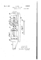
Fi'gurel iswasicle elevationof theapparatus,
Figure Zshows a workpiece onwhich the proc essis to .be carried out,,
Figure:3;is;an end. elevation of aviceincor porated-in-the apparatus and is to alarger scale;
Figures-4 :andrS'are views :of two insertsinth'e jaws vof the; vice,
Figure G-is a=section.- showing ithe :jaws of the vice :grippingthe.workpiece,
Figurel'l is: anj;oend.;elevation of. a support iorthe workpiecaz Figure '8 is, a side eleyationpf the support shown in Figure '7;
Fig-ure'9.-,is--a sideelevation of a device for. en gagingone :end of: the workpiece,
Figure. 101 is 'a ,plan ofythe device shown in Figure 9, and-7 Figure- 11 is-asectiongonzthe line i I,r| I of Fig-- ure 10.
The machine comprises aebe'dplate 20 0!; oneend of; which .-,is.; an. hydraulic ram 2 Iv and on the other end am insulated mounting '22 for an anvil 23.; The..mounting 22 is carried lay rods extendingabetween:pillars 25 011 the bedplate. A,
step-down transformer not shown.
Each vice jaw is formed with a semi-cylindrical recess to receive inserts and 3| which are retained therein by suitable means. Each jaw is formed with a longitudinal groove 32 of a width corresponding to the width of the workpiece 33 which is to be forged and of a depth equal to less than half the thickness of the workpiece. The workpiece will thus be received between the inserts in the grooves 32 and guided thereby. The lower insert 30 is further grooved at 34 along a central zone beneath the workpiece so that it only engages the workpiece on the underside along two broad side margins and not in the centre. The upper insert 3! is formed with two deeper grooves 35 so that it will not engage the said margins of the workpiece but will only engage it over a central zone.
The workpiece 33 is mounted in the apparatus with one end abutting the piston 36 of the ram and the other end clamped between the vice jaws 27 and 29. It is supported between the ram and the vice by a support shown in Figures 7 and 8 comprising a frame 31 which is mounted on the bars 24 and is formed with a bent portion 38 which is grooved at 39 to receive and guide the workpiece 33. The workpiece is retained in the groove 39 by a part 40 which is pivoted at 41 and engaged under a hook 42. The part 40 can be swung about its pivot clear of the workpiece to allow of its removal.
In producing leaves for laminated springs on this machine, a fiat steel bar to constitute the workpiece is taken which contains enough metal to produce an upset head of the desired size at each end and to leave the resulting forging of the required length, The workpiece is placed in the vice and the support and hydraulic pressure is applied simultaneously to the hydraulic rams 2i and 28. The workpiece is thus clamped in the vice and forced to slide through the vice towards the anvil so as to bear firmly against the latter. In this position current flows through the end of the workpiece between the vice and the anvil and this end is rapidly raised to forging temperature.
As soon as this stage is reached the ram 21 forces the workpiece further towards the anvil so that its end is upset into a hollowed out part 43 of the anvil so as to form the required head 44. As shown in Figure 2 the ends of the workpiece are tapered off in a horizontal plane so as to reduce the width of th workpiece at each end. The effeet is two fold: in the first place the reduced width at the end of the workpiece ensures that that end bears on the anvil with less unevenness than would be likely were the full width of the end of the workpiece to be engaging the anvil at this stage. Therefore the heat is not led towards one only of the two side margins of the bar as would otherwise be likely. In the second place, when the upsetting operation proceeds, the natural tendency of the workpiece to spread sideways as well as to swell up into the recess 43 of the anvil is counteracted and at the end of the upsetting operation the forged head will be approximately of the right dimensions laterally.
After upsetting the head at one end of the workpiece, the head is formed into a lug of the desired finished shape in a die-press. The bar is then reversed in the machine and a head upset at the other end or this operation may be conducted in a second machine of similar construction. During the second upsetting operation, the device ShOWn in Figures 9, l0 and 11 is fitted to the end of the ram piston 36 and serves to hold the lug already formed on the workpiece. The device comprises an extension 45 having a part 46 by which it can be fitted on to the end of the ram piston 35 and hollowed out at 47 to fit the lug 48 on the end of the workpiece. The lug 48 is held down into the recess by a part 49 which is pivoted at 50 on a swivel 5| and the swivel has a spindle 52 that is rotatable in the extension 45. The part 49 is engaged under a hook 53 which retains it against the top of the workpiece so as to hold the lug 48 in the recess 41. To remove the workpiece, the part 43 is swung in a horizontal plane about the spindle 52 till it is clear of the hook 53 and is then swung up about its pivot 52 so that th workpiece can be lifted off the extension 45.
The second upsetting operation is performed in the manner already described but it will be understood that the lug 48 previously formed is supported in the extension 45 of the ram 2! so that it cannot be deformed by the end pressure during the second upsetting operation. The head formed in the second upsetting operation is also formed to the desired finished shape in a diepress.
After the two upsetting operations, the spring is bent to the desired curve, should a curved spring be required, and the lugs are drilled out for the shackle pins. Finally the spring is tempered.
I claim:
1. Apparatus for electrical upsetting of flat bars comprising in combination a frame, an anvil, pressing means opposed to the anvil to exert endwise pressure on a fiat bar to be upset, means to bring the pressing means and the anvil nearer together to effect upsetting, a pair of vice-jaw electrodes, located between the pressing means and the anvil, adapted to bear on the fiat faces of the bar to be upset, one of said vice-jaws having a central bearing portion narrower than the width of the bar and the other having two lateral bearing portions spaced so that they are wider apart than the said central bearing portion, and means to supply current to the bar through both said vice-jaws of the anvil.
2. Apparatus according to claim 1, the said vice-jaw having a central bearing portion being the upper jaw of said pair.
3. Apparatus according to claim 1, said pressing means having a work-engaging portion shaped to lit the outline of a lug previously formed on the work-piece, and releasable means for retaining said lug in engagement with said work-engaging portion.
GRATO MORA.
REFERENCES CITED The following references are of record in the le of this patent:
UNITED STATES PATENTS Number Name Date 437,654 Lauder et a1 Sept. 30, 1890 483,424 Coffin Sept. 27, 1892 2,009,206 Rosner July 23, 1935 2,044,504 Kobert June 16, 1936 2,374,794 Westin May 1, 1945 1,653,056 Phelps Feb. 7, 1928 FOREIGN PATENTS Number Country Date 831,972 France June 20, 1938
Applications Claiming Priority (1)
| Application Number | Priority Date | Filing Date | Title |
|---|---|---|---|
| GB2430529X | 1944-05-05 |
Publications (1)
| Publication Number | Publication Date |
|---|---|
| US2430529A true US2430529A (en) | 1947-11-11 |
Family
ID=10906727
Family Applications (1)
| Application Number | Title | Priority Date | Filing Date |
|---|---|---|---|
| US613776A Expired - Lifetime US2430529A (en) | 1944-05-05 | 1945-08-31 | Manufacture of leaf springs |
Country Status (1)
| Country | Link |
|---|---|
| US (1) | US2430529A (en) |
Cited By (2)
| Publication number | Priority date | Publication date | Assignee | Title |
|---|---|---|---|---|
| US3090456A (en) * | 1961-04-04 | 1963-05-21 | Fairchild Stratos Corp | Electrically powered wheel |
| US3827275A (en) * | 1971-12-07 | 1974-08-06 | Hasenclever Gmbh Maschf | Method of and apparatus for the upsetting of bars and similar workpieces |
Citations (7)
| Publication number | Priority date | Publication date | Assignee | Title |
|---|---|---|---|---|
| US437654A (en) * | 1890-09-30 | laudee | ||
| US483424A (en) * | 1892-09-27 | Electric metal-working device | ||
| US1658056A (en) * | 1923-04-20 | 1928-02-07 | Murray | Electric pressing or forging machine |
| US2009206A (en) * | 1929-03-18 | 1935-07-23 | Bendix Brake Co | Metal working process |
| US2044504A (en) * | 1933-08-14 | 1936-06-16 | Kathryn Kobert | Muffle device |
| FR831972A (en) * | 1937-02-22 | 1938-09-16 | Manufacturing process for metal tie rods whose ends are shaped by electrical upsetting | |
| US2374794A (en) * | 1942-10-30 | 1945-05-01 | Smith Corp A O | Method and apparatus for electrically forming pipe |
-
1945
- 1945-08-31 US US613776A patent/US2430529A/en not_active Expired - Lifetime
Patent Citations (7)
| Publication number | Priority date | Publication date | Assignee | Title |
|---|---|---|---|---|
| US437654A (en) * | 1890-09-30 | laudee | ||
| US483424A (en) * | 1892-09-27 | Electric metal-working device | ||
| US1658056A (en) * | 1923-04-20 | 1928-02-07 | Murray | Electric pressing or forging machine |
| US2009206A (en) * | 1929-03-18 | 1935-07-23 | Bendix Brake Co | Metal working process |
| US2044504A (en) * | 1933-08-14 | 1936-06-16 | Kathryn Kobert | Muffle device |
| FR831972A (en) * | 1937-02-22 | 1938-09-16 | Manufacturing process for metal tie rods whose ends are shaped by electrical upsetting | |
| US2374794A (en) * | 1942-10-30 | 1945-05-01 | Smith Corp A O | Method and apparatus for electrically forming pipe |
Cited By (2)
| Publication number | Priority date | Publication date | Assignee | Title |
|---|---|---|---|---|
| US3090456A (en) * | 1961-04-04 | 1963-05-21 | Fairchild Stratos Corp | Electrically powered wheel |
| US3827275A (en) * | 1971-12-07 | 1974-08-06 | Hasenclever Gmbh Maschf | Method of and apparatus for the upsetting of bars and similar workpieces |
Similar Documents
| Publication | Publication Date | Title |
|---|---|---|
| US2953794A (en) | Process of forging pre-warmed metal stock within relatively low temperature limits | |
| US2473245A (en) | Forging or upsetting of metal rods or bars using electric resistance heating | |
| US2515841A (en) | Tube closing apparatus | |
| US2430529A (en) | Manufacture of leaf springs | |
| US3396567A (en) | Apparatus for the heading of conductive workpieces | |
| CN114700455A (en) | A kind of fork joint forging die forging die and its die forging method | |
| US2737224A (en) | Apparatus for forming sheet metal | |
| US2133874A (en) | Method and apparatus for extruding metal strips | |
| US3828601A (en) | Method and apparatus for producing a finished joint between ends of wires, rods and the like | |
| US2393155A (en) | Forging pointed articles | |
| US1417806A (en) | Method and apparatus for forming headed articles | |
| US2069980A (en) | Method of making chain links | |
| CN208083318U (en) | A kind of efficient pawl pole hot forging equipment | |
| CN109773095A (en) | It is a kind of for forging the technique of the hollow forging of high-carbon high-alloy cold work die steel | |
| US2058698A (en) | Method of and apparatus for forging and shaping metal articles | |
| US2305961A (en) | Electric forging apparatus | |
| US438409A (en) | dewey | |
| US2795976A (en) | Manufacture of cutlery | |
| US1857708A (en) | Forging | |
| US1867935A (en) | Electric upsetting apparatus | |
| US432630A (en) | Forming or shaping metals by electricity | |
| US2499281A (en) | Flash butt welding apparatus | |
| GB585825A (en) | Improvements in or relating to the manufacture of leaf springs | |
| US1313345A (en) | A cokpob-ation of | |
| CN205200420U (en) | A roll up and put chuck for spring make -up machine |