US2425797A - Heating system - Google Patents
Heating system Download PDFInfo
- Publication number
- US2425797A US2425797A US638250A US63825045A US2425797A US 2425797 A US2425797 A US 2425797A US 638250 A US638250 A US 638250A US 63825045 A US63825045 A US 63825045A US 2425797 A US2425797 A US 2425797A
- Authority
- US
- United States
- Prior art keywords
- air
- window
- space
- building
- heat exchange
- Prior art date
- Legal status (The legal status is an assumption and is not a legal conclusion. Google has not performed a legal analysis and makes no representation as to the accuracy of the status listed.)
- Expired - Lifetime
Links
- 238000010438 heat treatment Methods 0.000 title description 8
- 239000000543 intermediate Substances 0.000 description 3
- 238000010276 construction Methods 0.000 description 1
- 238000001816 cooling Methods 0.000 description 1
- 238000009434 installation Methods 0.000 description 1
- 238000005192 partition Methods 0.000 description 1
- XXPDBLUZJRXNNZ-UHFFFAOYSA-N promethazine hydrochloride Chemical compound Cl.C1=CC=C2N(CC(C)N(C)C)C3=CC=CC=C3SC2=C1 XXPDBLUZJRXNNZ-UHFFFAOYSA-N 0.000 description 1
- 230000005855 radiation Effects 0.000 description 1
- 238000003303 reheating Methods 0.000 description 1
Images

Classifications
-
- F—MECHANICAL ENGINEERING; LIGHTING; HEATING; WEAPONS; BLASTING
- F24—HEATING; RANGES; VENTILATING
- F24D—DOMESTIC- OR SPACE-HEATING SYSTEMS, e.g. CENTRAL HEATING SYSTEMS; DOMESTIC HOT-WATER SUPPLY SYSTEMS; ELEMENTS OR COMPONENTS THEREFOR
- F24D5/00—Hot-air central heating systems; Exhaust gas central heating systems
- F24D5/06—Hot-air central heating systems; Exhaust gas central heating systems operating without discharge of hot air into the space or area to be heated
- F24D5/08—Hot-air central heating systems; Exhaust gas central heating systems operating without discharge of hot air into the space or area to be heated with hot air led through radiators
Definitions
- This invention relates to a heating system and more particularly to a heating system for buildings such as dwellings, orifice-buildings andthe like.
- the primary object of the-invention is theefllcient heating of a -given -space without-the use of visible air ducts.
- Another object is to utilize the wall of a building as a heated air duct and to employ the window space normally provided in a building as the heat radiating area.
- this invention which embodies among its features a heat exchange unit connected to discharge heated air into an air duct built into the wall of 'a building, which air duct opens into the lower end of a window space into which the heated air is discharged for radiation into the space to be heated, a double glazed sash closing the outer side of the window space to conserve the heat, a single glazed sash closing the inner side of the window space, a return duct leading from the window space back to the heat exchange unit and circulating means in the system for creating a sub-atmospheric pressure in the return duct behind the heat exchange unit.
- a building block so constructed as to form an air space between an inter mediate wall and the outside face of the block, and an air duct between the intermediate wall and the inner face of the block by the use of which block concealed air ducts may be built into a wall.
- Figure 1 is a sectional view through a building showing this improved heating system installed therein
- Figure 2 is an enlarged sectional view through the walls of building showing in detail the window space and the manner in which it is glazed,
- Figure 3 is a perspective View of a building block employed in building a wall suitable for the installation of this heating system
- Figure 4 is a vertical sectional view taken substantially on the line 44 of Figure 1.
- a building designated generally H3 is provided with the usual footings l l upon which my improved building unit designated generally I2 are laid one upon the other to form a wall having a window opening 13 intermediate its upper and lower ends.
- the building unit 12 above comprises a hollow rectangular body l4 between opposite ends of which extends a longitudinal partition wall I5 dividing the block 14 into twoseparate chambers l6 and H respectively.
- the chamlbers l6 are arranged adjacent the outer face of the block to .form in the wall an insulating air spaceclosed at its upper end by. a window sill l8 arranged at thelower end of the window space l3 andthe lower end of the upper insulating spaceiabove theuwindow space l 3.is closed by. the window lintel IS.
- the gchamb ers l"l-in the blocks [4 align to form a"verticallyfextendingair duct the upper end of'which'opens into the window space l3 for the introduction of heated air into the Window space as will be more fully hereinafter explained.
- the blocks above the window space have their chambers ll aligned and communicate through a suitable opening in the lintel 19 with the window space l3 and form a part of the return duct as will be more fully hereinafter explained.
- the portion of the window opening l3 which faces the exterior of the building is closed by a double glazed sash l9 and the back portion of the window space l3 opening toward the interior of the building is closed by a single glazed sash 2H and the duct formed by the chamber ll of the blocks I2 opens into the chamber thus formed between the sash as will be readily understood as upon reference to the drawings.
- a warm air duct 22 connected to the discharge end of a suitable heat exchange unit 23.
- a return duct 24 leads from the duct formed by the chambers H in the blocks above the lintel of the window face 13 and thence leads downwardly to enter the heat exchange unit 23 at its intake side.
- a suitable suction fan 25 is interposed in the return duct 24 between the end connected to the duct formed by the blocks l4 above the window and the intake opening of the heat exchange unit 23, preferably adjacent the heat exchange unit as illustrated.
- the heat exchange unit 23 receives cooled air through the return duct 24 and suction fan 25 and through the contact of the air with the heat exchange unit warm air is discharged through the pipe 22 into the duct formed in the walls of the building by the chambers 11 in the blocks from whence it flows upwardly into the space between the double glazed sash and single glazed sash of the Window opening [3 the heat is then radiated through the single glazed sash 20 into the space to be heated and the cool air is drawn upwardly through the return duct 24 and back to the suction fan 25 where it is discharged again into the heat exchange unit 23 for reheating.
- the heat exchange unit 23 may take the form of a cooling unit in which event cooled air will be circulated through the system for the purpose of absorbing heat from the space in which the temperature is to be controlled. Due to the dead air space contained within the double glazed sash l9 heat loss through the window to the exterior of the building will be avoided.
- a closed heating system in combination with a heat exchange unit a building wall having a window space and an air duct therein opening into the bottom and. top of the window space, a double glazed sash closing the window space facing the outside of the Wall, a single glazed sash closin the window space adjacent the inside of the wall, said sash forming a chamber between them into the lower end of which warm air is fed through said air duct from said heat exchange unit, and a conduit establishin connection between the air duct opening into the upper end of the chamber and the cold air intake side of the heat exchange unit and a suction fan in the system adjacent the heat exchange unit to maintain a forced circulation of air at sub-atmospheric pressure through the system.
Landscapes
- Engineering & Computer Science (AREA)
- Physics & Mathematics (AREA)
- Thermal Sciences (AREA)
- Chemical & Material Sciences (AREA)
- Combustion & Propulsion (AREA)
- Mechanical Engineering (AREA)
- General Engineering & Computer Science (AREA)
- Specific Sealing Or Ventilating Devices For Doors And Windows (AREA)
- Building Environments (AREA)
Description
Aug. 19, 1947.- 1;. 1%? GILLESPIEI I HEATING SYSTEM Filed Dec. 29., 1945 2 Sheets-Sheet 1 I m/entor s o/ie Attorneys Patented Aug. 19, 1941 UNITED STATES IOF FIC'E .1 Claim.
This invention relates to a heating system and more particularly to a heating system for buildings such as dwellings, orifice-buildings andthe like.
The primary obiect of the-invention is theefllcient heating of a -given -space without-the use of visible air ducts.
Another object is to utilize the wall of a building as a heated air duct and to employ the window space normally provided in a building as the heat radiating area.
The above and other objects may be attained by employing this invention which embodies among its features a heat exchange unit connected to discharge heated air into an air duct built into the wall of 'a building, which air duct opens into the lower end of a window space into which the heated air is discharged for radiation into the space to be heated, a double glazed sash closing the outer side of the window space to conserve the heat, a single glazed sash closing the inner side of the window space, a return duct leading from the window space back to the heat exchange unit and circulating means in the system for creating a sub-atmospheric pressure in the return duct behind the heat exchange unit.
Other features include a building block so constructed as to form an air space between an inter mediate wall and the outside face of the block, and an air duct between the intermediate wall and the inner face of the block by the use of which block concealed air ducts may be built into a wall.
In the drawings:
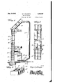
Figure 1 is a sectional view through a building showing this improved heating system installed therein,
Figure 2 is an enlarged sectional view through the walls of building showing in detail the window space and the manner in which it is glazed,
Figure 3 is a perspective View of a building block employed in building a wall suitable for the installation of this heating system, and
Figure 4 is a vertical sectional view taken substantially on the line 44 of Figure 1.
Referring to the drawings in detail a building designated generally H3 is provided with the usual footings l l upon which my improved building unit designated generally I2 are laid one upon the other to form a wall having a window opening 13 intermediate its upper and lower ends.
The building unit 12 above comprises a hollow rectangular body l4 between opposite ends of which extends a longitudinal partition wall I5 dividing the block 14 into twoseparate chambers l6 and H respectively. The chamlbers l6 are arranged adjacent the outer face of the block to .form in the wall an insulating air spaceclosed at its upper end by. a window sill l8 arranged at thelower end of the window space l3 andthe lower end of the upper insulating spaceiabove theuwindow space l 3.is closed by. the window lintel IS. The gchamb ers l"l-in the blocks [4 align to form a"verticallyfextendingair duct the upper end of'which'opens into the window space l3 for the introduction of heated air into the Window space as will be more fully hereinafter explained. The blocks above the window space have their chambers ll aligned and communicate through a suitable opening in the lintel 19 with the window space l3 and form a part of the return duct as will be more fully hereinafter explained.
The portion of the window opening l3 which faces the exterior of the building is closed by a double glazed sash l9 and the back portion of the window space l3 opening toward the interior of the building is closed by a single glazed sash 2H and the duct formed by the chamber ll of the blocks I2 opens into the chamber thus formed between the sash as will be readily understood as upon reference to the drawings.
Connected through a suitable port 2| formed in one of the lower blocks in the wall opening into the chamber I! in said block is a warm air duct 22 connected to the discharge end of a suitable heat exchange unit 23. A return duct 24 leads from the duct formed by the chambers H in the blocks above the lintel of the window face 13 and thence leads downwardly to enter the heat exchange unit 23 at its intake side. In order to establish circulation through the system a suitable suction fan 25 is interposed in the return duct 24 between the end connected to the duct formed by the blocks l4 above the window and the intake opening of the heat exchange unit 23, preferably adjacent the heat exchange unit as illustrated.
In operation it will 'be understood that the heat exchange unit 23 receives cooled air through the return duct 24 and suction fan 25 and through the contact of the air with the heat exchange unit warm air is discharged through the pipe 22 into the duct formed in the walls of the building by the chambers 11 in the blocks from whence it flows upwardly into the space between the double glazed sash and single glazed sash of the Window opening [3 the heat is then radiated through the single glazed sash 20 into the space to be heated and the cool air is drawn upwardly through the return duct 24 and back to the suction fan 25 where it is discharged again into the heat exchange unit 23 for reheating.
By the use of a closed system of this nature the air employed for carrying the heat to the desired points of distribution is in no way effected by changes of temperature or humidity of the surrounding atmosphere and a negative pressure is maintained through the greaterpart of the system by the use of the suction fan 25.
Obviously the heat exchange unit 23 may take the form of a cooling unit in which event cooled air will be circulated through the system for the purpose of absorbing heat from the space in which the temperature is to be controlled. Due to the dead air space contained within the double glazed sash l9 heat loss through the window to the exterior of the building will be avoided.
While in the foregoin there has been shown and described the preferred embodiment of this invention it is to be understood that minor changes in the details of construction, combination and arrangement of parts may be resorted to without departin from the spirit and scope of the invention as claimed.
I claim:
In a closed heating system in combination with a heat exchange unit a building wall having a window space and an air duct therein opening into the bottom and. top of the window space, a double glazed sash closing the window space facing the outside of the Wall, a single glazed sash closin the window space adjacent the inside of the wall, said sash forming a chamber between them into the lower end of which warm air is fed through said air duct from said heat exchange unit, and a conduit establishin connection between the air duct opening into the upper end of the chamber and the cold air intake side of the heat exchange unit and a suction fan in the system adjacent the heat exchange unit to maintain a forced circulation of air at sub-atmospheric pressure through the system.
ELWYN R. GILLESPIE.
REFERENCES CITED The following references are of record in the file of this patent:
UNITED STATES PATENTS Number Name Date 2,240,951 I-Iamjy May 6, 1941 1,467,005 Lawrence Sept. 4, 1923 676,296 Allison June 11, 1901 2,107,523 Coe Feb. 8, 1938
Priority Applications (1)
| Application Number | Priority Date | Filing Date | Title |
|---|---|---|---|
| US638250A US2425797A (en) | 1945-12-29 | 1945-12-29 | Heating system |
Applications Claiming Priority (1)
| Application Number | Priority Date | Filing Date | Title |
|---|---|---|---|
| US638250A US2425797A (en) | 1945-12-29 | 1945-12-29 | Heating system |
Publications (1)
| Publication Number | Publication Date |
|---|---|
| US2425797A true US2425797A (en) | 1947-08-19 |
Family
ID=24559250
Family Applications (1)
| Application Number | Title | Priority Date | Filing Date |
|---|---|---|---|
| US638250A Expired - Lifetime US2425797A (en) | 1945-12-29 | 1945-12-29 | Heating system |
Country Status (1)
| Country | Link |
|---|---|
| US (1) | US2425797A (en) |
Cited By (8)
| Publication number | Priority date | Publication date | Assignee | Title |
|---|---|---|---|---|
| US2557906A (en) * | 1948-03-20 | 1951-06-19 | Budd Co | System of modulated room and window heating |
| US2693939A (en) * | 1949-05-06 | 1954-11-09 | Marchant Lewis | Heating and cooling system |
| US3107052A (en) * | 1959-05-08 | 1963-10-15 | Joel F Garrison | Radiation collectors |
| US3742837A (en) * | 1971-07-14 | 1973-07-03 | Svenska Flaektfabriken Ab | Arrangement at ventilation installations in rooms provided with exhaust air windows and lighted by a number of fittings |
| US4069809A (en) * | 1976-07-19 | 1978-01-24 | Strand Lyle L | Solar heat collecting porous building blocks |
| US4111183A (en) * | 1976-07-01 | 1978-09-05 | Haberthier Wilbert L | Solar heating unit |
| US4296733A (en) * | 1976-08-05 | 1981-10-27 | Saunders Norman B | Heating, lighting and ventilation systems |
| US20160038255A1 (en) * | 2013-03-14 | 2016-02-11 | Daniel R. Llop | Bone foundation guide system and method |
Citations (4)
| Publication number | Priority date | Publication date | Assignee | Title |
|---|---|---|---|---|
| US676296A (en) * | 1901-03-19 | 1901-06-11 | Robert Emil Allison | Device for preventing the formation of frost on window-panes. |
| US1467005A (en) * | 1921-09-22 | 1923-09-04 | Lawrence John | Ventilating, heating, cooling, and shade apparatus for rooms |
| US2107523A (en) * | 1935-11-15 | 1938-02-08 | Elbert H Coe | Building structure |
| US2240951A (en) * | 1939-10-26 | 1941-05-06 | Internat Heater Company | Heating system for buildings |
-
1945
- 1945-12-29 US US638250A patent/US2425797A/en not_active Expired - Lifetime
Patent Citations (4)
| Publication number | Priority date | Publication date | Assignee | Title |
|---|---|---|---|---|
| US676296A (en) * | 1901-03-19 | 1901-06-11 | Robert Emil Allison | Device for preventing the formation of frost on window-panes. |
| US1467005A (en) * | 1921-09-22 | 1923-09-04 | Lawrence John | Ventilating, heating, cooling, and shade apparatus for rooms |
| US2107523A (en) * | 1935-11-15 | 1938-02-08 | Elbert H Coe | Building structure |
| US2240951A (en) * | 1939-10-26 | 1941-05-06 | Internat Heater Company | Heating system for buildings |
Cited By (8)
| Publication number | Priority date | Publication date | Assignee | Title |
|---|---|---|---|---|
| US2557906A (en) * | 1948-03-20 | 1951-06-19 | Budd Co | System of modulated room and window heating |
| US2693939A (en) * | 1949-05-06 | 1954-11-09 | Marchant Lewis | Heating and cooling system |
| US3107052A (en) * | 1959-05-08 | 1963-10-15 | Joel F Garrison | Radiation collectors |
| US3742837A (en) * | 1971-07-14 | 1973-07-03 | Svenska Flaektfabriken Ab | Arrangement at ventilation installations in rooms provided with exhaust air windows and lighted by a number of fittings |
| US4111183A (en) * | 1976-07-01 | 1978-09-05 | Haberthier Wilbert L | Solar heating unit |
| US4069809A (en) * | 1976-07-19 | 1978-01-24 | Strand Lyle L | Solar heat collecting porous building blocks |
| US4296733A (en) * | 1976-08-05 | 1981-10-27 | Saunders Norman B | Heating, lighting and ventilation systems |
| US20160038255A1 (en) * | 2013-03-14 | 2016-02-11 | Daniel R. Llop | Bone foundation guide system and method |
Similar Documents
| Publication | Publication Date | Title |
|---|---|---|
| US2210960A (en) | Air conditioning system | |
| US2559871A (en) | House structure and heating system therefor | |
| US2559870A (en) | House heating system | |
| US3343474A (en) | Building with a vent device | |
| US4462459A (en) | Device for air control of an energy facade wall | |
| US2206119A (en) | Building heating and cooling system | |
| US2364220A (en) | Building | |
| US2425797A (en) | Heating system | |
| US2962218A (en) | Hot air heating system | |
| US2355495A (en) | Heating and air conditioning system | |
| US4741391A (en) | Method and apparatus for recovering of transmitted heat | |
| US2986904A (en) | Heat pump space heating system | |
| US2587871A (en) | House trailer heating system | |
| US1539611A (en) | Air-ventilated construction and building unit used in connection therewith | |
| JPH0293228A (en) | Ventilating device for building | |
| US2561290A (en) | Heating apparatus | |
| US1798892A (en) | Heater | |
| US2074370A (en) | Air conditioning and ventilation of houses | |
| US982721A (en) | Apparatus for heating, cooling, and ventilating buildings. | |
| US2224878A (en) | Air cooling and circulating device | |
| US445486A (en) | andeews | |
| US1830099A (en) | Heating and cooling system | |
| JP6114564B2 (en) | Air conditioning system and building | |
| SE442132B (en) | DEVICE FOR WINDOWS TO BRING THE INSIDE BOX A CRAFT COMFORTABLE APPROPRIATE EXTERNAL TEMPERATURE | |
| JP2934159B2 (en) | Ventilated structures |