US242567A - smith - Google Patents
smith Download PDFInfo
- Publication number
- US242567A US242567A US242567DA US242567A US 242567 A US242567 A US 242567A US 242567D A US242567D A US 242567DA US 242567 A US242567 A US 242567A
- Authority
- US
- United States
- Prior art keywords
- piston
- cylinder
- valve
- ports
- propeller
- Prior art date
- Legal status (The legal status is an assumption and is not a legal conclusion. Google has not performed a legal analysis and makes no representation as to the accuracy of the status listed.)
- Expired - Lifetime
Links
- XLYOFNOQVPJJNP-UHFFFAOYSA-N water Substances O XLYOFNOQVPJJNP-UHFFFAOYSA-N 0.000 description 8
- 238000005192 partition Methods 0.000 description 4
- 238000010276 construction Methods 0.000 description 2
- 210000003414 extremity Anatomy 0.000 description 2
- 241000345822 Cylindera <genus> Species 0.000 description 1
- 230000009286 beneficial effect Effects 0.000 description 1
- 238000005242 forging Methods 0.000 description 1
- 230000007935 neutral effect Effects 0.000 description 1
- 229920000136 polysorbate Polymers 0.000 description 1
- 238000009877 rendering Methods 0.000 description 1
- 239000000126 substance Substances 0.000 description 1
- 210000001364 upper extremity Anatomy 0.000 description 1
Images
Classifications
-
- B—PERFORMING OPERATIONS; TRANSPORTING
- B63—SHIPS OR OTHER WATERBORNE VESSELS; RELATED EQUIPMENT
- B63H—MARINE PROPULSION OR STEERING
- B63H1/00—Propulsive elements directly acting on water
- B63H1/30—Propulsive elements directly acting on water of non-rotary type
- B63H1/32—Flaps, pistons, or the like, reciprocating in propulsive direction
Definitions
- This invention relates to propellers having hinged blades; and it consists, chiefly, in a pair of longitudinally-reciprocating shafts having a pin-and-slot connection with each other, and connected,respectively,with the pintle and with the sides of said blades, for the purpose hereinafter set forth.
- FIG. 1 a horizontal section
- Fig. 2 a sectional side elevation of a part of my mechanism
- Fig. 3 a similar view of another part
- Fig. 4 a vertical crosssection of a device ormechanism containing my invention, taken through the cylinder-valves
- Fig. 5 is a plan of the valve and valveseats
- Fig. 6 of the drawings is a cross-section of the cylinders and valve-chest
- Fig. 7 a plan of the lower chamber of said chest.
- Fig. 8 represents the propeller as applied to a vessel.
- Fig. 9 represents a plan or the cylinder-valves.
- a B represent two horizontal steam-cylinders, preferably of equal length and capacity, arranged side by side, and containing each a piston, G or H, and pistonrod K or L, while upon the top of the combined cylinders is a closed steam chest, D, which is divided horizontally by a partition, I, into two chambers, D and J, the first and upper one,
- I constituting an intermediate chamber be tween the valve-chest and cylinders.
- I create .two ports or sets of ports, E 'E E E leading to the chamber J below, and operating with these ports I dispose, within the valvechamber D, a flat valve, 0, of sufficient area to cover one opening or set of openings, the valve beingprovided with a lever, S, fulcrumed to the adj acentpart of the steam-chest, by which such valve may be moved laterally upon its seat and changed in position from one opening to the other, at the will of theengineer.
- the chamber J of the steam-chest is divided longitudinally by av vertical partition, J, into two inclosures, U U, one inclosure, U, communicating with the cylinder A, and the other, U, with the cylinder B.
- I create a live-steam port,W W or Y Y the ports W W leading to opposite ends of the interior of the cylinder A, and the ports Y Y to the corresponding parts of the cylinder B.
- valve-chamber D being always open to entrance of live steam by its inlet-port B it follows that when the valveO is over and coveringoncport or set ot'ports-say E E, as shown in Fig. 5 of the drawings-steam is excluded from the inclosure U and cylinder B, with which these ports communicate, while the ports E E are open and permitting live steam to pass to the inclosure U and the cylinder A, and vice versa.
- the port W has a seat, 0 the port W has a seat, 0 the port Y has a seat, (P, and the port Y has a seat, d
- the port W has a valve, 0 the port W has a valve, 6 the port Y has a valve h, and the port Y a valve, h.
- the stems of the valves taken in order with the numerical arrangement of the valves, as above, are shown-those valves of the livesteam port-s W W at 5 41 of the livesteam ports Y Y at j 9' those of the exhaust-ports W V at k k, and of the exhaust-ports Y Y at l i
- the stems of the live-steam valves are each connected at their upper ends to the extremity of the lower and horizontal arm, m of a bell-crank lever, 01/ n or 0 0 these cranks being of like size and shape, and the two of each set being piv'oted at their angles or corners to ahorizontal rod, 1) or 1)", these rods being supported at each end in posts or standards q (1 or 0" T2, erected upon the outside of the cylinder.
- each bell-crank lever is formed with a vertical arm, v and the upper extremity of the arms of one set of levers are connected to those of the opposite set by horizontal rods t &c., in such manner that as the valves at one end of the cylinder rise and open their ports those of the other end close upon their seats, each pair of valves thus connected being independentof the others, and their bellcrank levers turning freely upon their respective supports.
- the exhaust-valve e now closes and the opposite exhaust-valve, 0 opens, while the valve to closes, and a opens and permits of entrance of live steam to this end of the cylinder, thus driving the piston G, with its adjuncts, in the opposite or return direction a distance equal to the length of the slot 00, (minus the thickness of the yoke P,) thereby closing the blades 2 z.
- the piston G, with its adjuncts, now completes its stroke and returns to the starting-point, the piston H and its connections following, the folded propeller being in the act drawn inward to its full extent in readiness for a second advance.
- the cylinderA and piston G are for driving the vessel ahead, and I have explained above how they exert this function in connection with the propeller.
- valve 0 is moved laterally upon its seat in the steamchest D,by means of its lever, from over the ports E E of the cylinder B, and so as to expose these ports, while the ports E E of the cylinder A are closed, thereby rendering the said cylinder A passive by excluding steam from it.
- a cross-head serving to carry, guide, and brace the said blades, said cross-head bearin g against the backs of said blades when they are forced against the water.
- a pair of engines and devices for shifting the power from one to the other substantially as de scribed, whereby only one engine is operated at a time as the motor, though either engine may be so operated, according to the desired forward or backward direction of motion.
- the rod K with its outer tubular portion or propeller-shaft M, crosshead (I, and the wings z z, hinged at their bases to such cross-head, the rod L, bent and entering the tubular shaft M and provided with the stop or yoke P, to regulate the slip between the two rods, and bearin g the arm T, connected by links with the outer edges of the Wings 22, the whole being substantially as stated.
Landscapes
- Chemical & Material Sciences (AREA)
- Engineering & Computer Science (AREA)
- Combustion & Propulsion (AREA)
- Mechanical Engineering (AREA)
- Ocean & Marine Engineering (AREA)
- Control Of Turbines (AREA)
Description
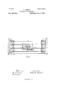
(No Model.) 4 Sheets-Sheet 1. B. SMITH. Vibrating Propeller. No. 242,567. Patented June 7,1881.
QNLJM (No Model.) 4 Sheets-Sheet 3.
B. SMITH Vibrating Propeller. 7 No. 242,567. Patented June 7,1881. fig;
\ GyZificZerfl/zorierzzd. 3
Witnesses. [7217mm]? k N. FEIERS; Fholo-Ulhngrapher. Wnshinginn, D. C.
(No Model.) 4 Sheets-Sheet 4. R. -S MITH;
I Vibrating Propeller. No. 242,567. Pater lied June 7,1881.
N PEI'ERS. mwumo ra nur. \vmm m. o. c.
UNITED STATES PATENT OFFICE.
RICHARD SMITH, on SHERBROOKE, QUEBEC, cannon, ASSIGNOR To JOHN ROAOH, TRUSTEE, on NEW YORK, N. v.
VIBRATING PROPELLER.
SPECIFICATION forming part of Letters Patent No. 242,567, dated June '7, 1881.
Application filed October 29, 1880.
To all whom it may concern Be it known that I, RICHARD SMITH, a citizen of the Dominion of Canada, residing at Sherbrooke, in the Province of Quebec, have invented certain new and useful Improvements in Reciprocating Propellers for Vessels; and I do hereby declare the following to be a full, clear, and exact description of the invention, such as will enable others skilled in the art to which it appertains to make and use the same, reference being had to the aecompan yin g drawings, and to letters or figures of reference marked thereon, which form a part of this specification.
This invention relates to propellers having hinged blades; and it consists, chiefly, in a pair of longitudinally-reciprocating shafts having a pin-and-slot connection with each other, and connected,respectively,with the pintle and with the sides of said blades, for the purpose hereinafter set forth.
It also consists in the combination, with the above, of two independent engines and ports and valves for shifting power from one shaft to the other.
Italso consists in certain minor though valuable improvements, which will hereinafter be set forth and claimed.
The drawings accompanying this specificationrepresent, in Figure 1, a horizontal section; in Fig. 2 a sectional side elevation of a part of my mechanism; in Fig. 3 a similar view of another part; and in Fig. 4 a vertical crosssection of a device ormechanism containing my invention, taken through the cylinder-valves; while Fig. 5 is a plan of the valve and valveseats. Fig. 6 of the drawings is a cross-section of the cylinders and valve-chest, and Fig. 7 a plan of the lower chamber of said chest. Fig. 8 represents the propeller as applied to a vessel. Fig. 9 represents a plan or the cylinder-valves.
In the drawings, A B represent two horizontal steam-cylinders, preferably of equal length and capacity, arranged side by side, and containing each a piston, G or H, and pistonrod K or L, while upon the top of the combined cylinders is a closed steam chest, D, which is divided horizontally by a partition, I, into two chambers, D and J, the first and upper one,
(No model.)
D, being the valve-chest, and the lower one,
J, constituting an intermediate chamber be tween the valve-chest and cylinders. In opposite sides of the partition or valve-seat I, I create .two ports or sets of ports, E 'E E E leading to the chamber J below, and operating with these ports I dispose, within the valvechamber D, a flat valve, 0, of sufficient area to cover one opening or set of openings, the valve beingprovided with a lever, S, fulcrumed to the adj acentpart of the steam-chest, by which such valve may be moved laterally upon its seat and changed in position from one opening to the other, at the will of theengineer.
The chamber J of the steam-chest is divided longitudinally by av vertical partition, J, into two inclosures, U U, one inclosure, U, communicating with the cylinder A, and the other, U, with the cylinder B. In opposite corners, upon one side of each inclosure U U, I create a live-steam port,W W or Y Y the ports W W leading to opposite ends of the interior of the cylinder A, and the ports Y Y to the corresponding parts of the cylinder B.
The valve-chamber D being always open to entrance of live steam by its inlet-port B it follows that when the valveO is over and coveringoncport or set ot'ports-say E E, as shown in Fig. 5 of the drawings-steam is excluded from the inclosure U and cylinder B, with which these ports communicate, while the ports E E are open and permitting live steam to pass to the inclosure U and the cylinder A, and vice versa.
1n lieu of governing the ports which control admission of steam to the cylinder directly by the primary valve 0, as is usual in steamengines, I proceed as follows: At the point where each live-steam port V W or Y Y enters its respective cylinder I form a valve-seat, 0 ff and g g, and upon this seat I place a puppet-valve, a, a, a or a (See Figs. 4 and 7.) Furthermore, I create in the substance of each end of the cylinders, or in abox, b placed on the cylinders and alongside the valve-seats f 5 f of the cylinder A and g g of the cylinder B, ports WV W and Y Y these latter ports being exhaust-ports and leading to the atmosphere and separated from the others by partitions Z The port W has a seat, 0 the port W has a seat, 0 the port Y has a seat, (P, and the port Y has a seat, d The port W has a valve, 0 the port W has a valve, 6 the port Y has a valve h, and the port Y a valve, h.
The stems of the valves, taken in order with the numerical arrangement of the valves, as above, are shown-those valves of the livesteam port-s W W at 5 41 of the livesteam ports Y Y at j 9' those of the exhaust-ports W V at k k, and of the exhaust-ports Y Y at l i The stems of the live-steam valves are each connected at their upper ends to the extremity of the lower and horizontal arm, m of a bell-crank lever, 01/ n or 0 0 these cranks being of like size and shape, and the two of each set being piv'oted at their angles or corners to ahorizontal rod, 1) or 1)", these rods being supported at each end in posts or standards q (1 or 0" T2, erected upon the outside of the cylinder. The stems of the exhaust-valves are also each secured at its upper end to the extremity of the lower arm, m of a bell-crank lever, it, these cranks being of like size and shape as the first, and the two of each setlikewise being pivoted to or upon the rods 11' 12 Furthermore, each bell-crank lever is formed with a vertical arm, v and the upper extremity of the arms of one set of levers are connected to those of the opposite set by horizontal rods t &c., in such manner that as the valves at one end of the cylinder rise and open their ports those of the other end close upon their seats, each pair of valves thus connected being independentof the others, and their bellcrank levers turning freely upon their respective supports.
To operate the bellcrank levers and the valves at'eaeh traverse of the piston in the respective cylinders I erect upon each pistonrod, outside of the cylinder, arms, which are to be so situated as to intercept the levers.
I do not in any sense limit myself to the abo ve-described means of operatin g the piston s G H, as various mechanical devices may be employed for the purpose. My object in representing and describing them is to illustrate one means of accomplishing the result.
The essential feature of my invention is the construction and operation of the folding propeller, and these I will now describe.
To the outer end of the piston-rod K, I secure a tubular hub or shaft, M, which I term the "propeller-shaft, since it drives the propeller rearward to force the vessel forward, and to the outer end of this shaft, and at right angles to its axis, I affix a vertical cross-head, d, which slides at top, and bottom in ways or guides in the stern of the vessel. (See Fig. 8 of the drawings.)
To the center of the cross-head d, and in axial alignment with the axis of the shaft M, I hinge or pivotthe inner edges of two flat wings or blades, 2 2, which together constitute the body of the folding propeller, the length and width of these blades being governed by the character and capacity of the vessel to which they are applied.
As the piston-rod K and propeller-shaft M extend in a straight line from the cylinder A it becomes necessary, under the present construction, to divert the piston-rod L of the backing-cylinder from a straight line, in order that its outer end may enter the shaft M, and to this end I bend the said rod L by securing to its outer end a lateral yoke, P, and to the opposite end of this yoke I secure the inner end of a secondary rod or extension, R, while the end of the yoke enters and slides within the bore of the shaft M, a slot, as, being created in one side of said shaft to permit ofshort longitudinal play of the end of the yoke within such bore, and by and with the piston-rod L R. The yoke P serves not only as a bend to the piston'rod, but as means of compelling the pistons and piston-rods of the two cylinders to move together, as hereinafter explained.
To the outer end of the rod R, I atfix a crossarm, T, and I slot opposite sides of the adjacent part of the shaft M, as shown at s s, to permit of play of this arm by and with the rod, while to each end of such arm I pivot one end of one of two twin links, 17 1;, the other ends of such links being pivoted, respectively, to the outer edges of the blades 2, as shown in Figs. 1 and 2 of the drawings.
The operation of the above-described mechanism is as follows, promising that the parts stand in the relative positions as shown in Figs. 1 and 2 ofthe drawings, in which the two pistons G H stand at the extreme outer ends of their respective cylinders-the propeller-blades being closed in the position in which they were left on the retreat of the propeller, and in readiness to expand on the outgoing of the pistons, and the yoke P and arm T standing at their extreme outward positions with respect to the tubular shaft M and its slots 00 s s, and finally with the valve 0 over and closing the ports E E of the valve-chamber D-the ports E E open and the live-steam valves a a" being open and a (6 closed: Steam being let on enters chamber U, thence passes by the open portW into the adjacent end of the cylinder A and drives its piston G and its rod K, and the shaft M, with its cross-head d, outward, or in the direction of the arrow 2, the piston [I and its rod L, with the rod R and arm T, remaining for the time stationary, the result being that the wings z z are opened by the advance of the shaft M and its cross-head, and when the shaft has advanced over and about the rod R a sufficient distance to open the wings to a flat plane, the inner boundary of the slot a: lying up against the yoke P, while at the same time the inner boundaries of the slots 8 8 lie up against the arm T, and the piston H, with its rods L and R and arm T, keep company with the piston G and its adjuncts until the traverse of the latter is completed, the piston G being in advance of the piston H a distance equal to the length of the slot :12, minus the IIO thickness of the yoke P, and the exhaust-steam escaping by the port Y As the piston Gr completes its stroke (followed by the piston H a short distance in rear, as stated) the valve 6 remains open and permits steam to exhaust from the cylinder. The exhaust-valve e now closes and the opposite exhaust-valve, 0 opens, while the valve to closes, and a opens and permits of entrance of live steam to this end of the cylinder, thus driving the piston G, with its adjuncts, in the opposite or return direction a distance equal to the length of the slot 00, (minus the thickness of the yoke P,) thereby closing the blades 2 z. The piston G, with its adjuncts, now completes its stroke and returns to the starting-point, the piston H and its connections following, the folded propeller being in the act drawn inward to its full extent in readiness for a second advance.
The-action of the propeller in retreating, as last explained, is not altogether a neutral one. As the blades close they tend, as a natural consequence, to crowd the water from between them. Hence they exert a certain amount of IESlStttlHG against the Water, which aids in forging the vessel ahead; while, as the remainder of the retreat movement of the propeller is accomplished very rapidly, owing to the slight resistance to the water, the vessel loses little headway if but a single propeller be employed. I propose, however, to employ upon vessels of considerable size duplicate propellers operating alternately.
It will be seen that as the blades of the propeller open prior to the latter starting on its outward traverse the outer edges of the blades remain stationary, while the inner edges or hinge are pushed outward; consequently a pushing action is by this movement exerted upon the water, which tends to drive the vessel ahead.
It is important that the ends of the links be pivoted to the extreme outer edges of the blades, for the reason that by so doing the whole surface of the bladeswings outward and exerts a pushing action upon the water. It the ends of the links were pivoted at a distance from the edges of the blades, the portions ofsuch blades outside of thepivots would exert a drawing action upon the water, and neutralize the beneficial action of the portions inside of such pivots.
As I have stated, the cylinderA and piston G are for driving the vessel ahead, and I have explained above how they exert this function in connection with the propeller.
I have also stated that the cylinder B and piston H are to be employed for reversing or backing the vessel, and I will now explain how this is accomplished. The valve 0 is moved laterally upon its seat in the steamchest D,by means of its lever, from over the ports E E of the cylinder B, and so as to expose these ports, while the ports E E of the cylinder A are closed, thereby rendering the said cylinder A passive by excluding steam from it. Steam being admitted into cylinder B behind its piston H, in manner as described with cylinder A, said piston H is forced outward or forward (the yoke P standing at the outer boundary of the slot at, and the propellerblade being already closed) until the tubular shaft M, piston-rod K, piston G, and the folded propeller are driven the full length of the stroke, when the live steam is admitted into the opposite end of the cylinder B, forcing the piston H in the reverse direction until the yoke P brings up against the inner boundary of the slot 00 and actuates the shaft M and its connections, when the piston H and its adjuncts complete their stroke, followed by the piston G and its connections, the result being that the open propeller is drawn inward and exerts its action upon the water to back the vessel, the direct and exhaust valves of the cylinder B operating precisely as those of the cylinder A, before described.
Having thus explained the nature and operation of my invention, I claim and desire to secure by Letters Patent the following:
1. In reciprocating propellers for navigable vessels, two steam-cylinders, pistons, and rods, in combination with the two propeller-blades hinged together at their inner edges, one piston-rod being connected with the hinge of the blades and the other with the outer edges of such blades, and the whole operating substantially as explained.
2. In combination with the hinged blades, a cross-head serving to carry, guide, and brace the said blades, said cross-head bearin g against the backs of said blades when they are forced against the water.
3. In combination with the hinged blades and two interlocking reciprocating shafts, a pair of engines and devices for shifting the power from one to the other, substantially as de scribed, whereby only one engine is operated at a time as the motor, though either engine may be so operated, according to the desired forward or backward direction of motion.
4. In combination, the rod K, with its outer tubular portion or propeller-shaft M, crosshead (I, and the wings z z, hinged at their bases to such cross-head, the rod L, bent and entering the tubular shaft M and provided with the stop or yoke P, to regulate the slip between the two rods, and bearin g the arm T, connected by links with the outer edges of the Wings 22, the whole being substantially as stated.
In testimony whereof I aflix my signature in presence of two witnesses.
RICHARD SMITH. Witnesses:
F. G. SIMPSON, H. E. LODGE.
Publications (1)
| Publication Number | Publication Date |
|---|---|
| US242567A true US242567A (en) | 1881-06-07 |
Family
ID=2311901
Family Applications (1)
| Application Number | Title | Priority Date | Filing Date |
|---|---|---|---|
| US242567D Expired - Lifetime US242567A (en) | smith |
Country Status (1)
| Country | Link |
|---|---|
| US (1) | US242567A (en) |
-
0
- US US242567D patent/US242567A/en not_active Expired - Lifetime
Similar Documents
| Publication | Publication Date | Title |
|---|---|---|
| US242567A (en) | smith | |
| US719222A (en) | Balanced rotary engine. | |
| US215314A (en) | Improvement in rotary steam-engines | |
| US1084512A (en) | Multiple-power engine. | |
| US313366A (en) | Compound steam engine | |
| US670867A (en) | Engine. | |
| US889622A (en) | Steam-engine. | |
| US401167A (en) | Compound steam-engine | |
| US285998A (en) | Oscillating steam-engine | |
| US324222A (en) | Half to a | |
| US679229A (en) | Rotary engine. | |
| US213726A (en) | Improvement in rotary engines | |
| US288787A (en) | Reversing and expansion valve gear | |
| USRE9857E (en) | guild | |
| US212019A (en) | Improvement in valve-gears for steam-engines | |
| US645122A (en) | Automatic cut-off for engines. | |
| US656963A (en) | Valve. | |
| US548812A (en) | Rotary engine | |
| US264507A (en) | Botary engin | |
| US743615A (en) | Reversing-valve gear. | |
| US167509A (en) | Improvement in steasvi-engines | |
| US327335A (en) | Propellers | |
| US321325A (en) | hodges | |
| US430288A (en) | Compound vibrating-piston engine | |
| US1221085A (en) | Water-driven engine. |