US2425451A - Front feed mechanism for writing machines - Google Patents
Front feed mechanism for writing machines Download PDFInfo
- Publication number
- US2425451A US2425451A US675956A US67595646A US2425451A US 2425451 A US2425451 A US 2425451A US 675956 A US675956 A US 675956A US 67595646 A US67595646 A US 67595646A US 2425451 A US2425451 A US 2425451A
- Authority
- US
- United States
- Prior art keywords
- sheet
- work
- gage
- gaging
- bar
- Prior art date
- Legal status (The legal status is an assumption and is not a legal conclusion. Google has not performed a legal analysis and makes no representation as to the accuracy of the status listed.)
- Expired - Lifetime
Links
- 230000007246 mechanism Effects 0.000 title description 5
- 230000015572 biosynthetic process Effects 0.000 description 2
- 238000005755 formation reaction Methods 0.000 description 2
- 239000002184 metal Substances 0.000 description 2
- 230000009471 action Effects 0.000 description 1
- 230000008859 change Effects 0.000 description 1
- 239000002131 composite material Substances 0.000 description 1
- 230000006835 compression Effects 0.000 description 1
- 238000007906 compression Methods 0.000 description 1
- 230000001143 conditioned effect Effects 0.000 description 1
- 238000010276 construction Methods 0.000 description 1
- 238000007598 dipping method Methods 0.000 description 1
- 210000005069 ears Anatomy 0.000 description 1
- 238000000034 method Methods 0.000 description 1
- 230000004048 modification Effects 0.000 description 1
- 238000012986 modification Methods 0.000 description 1
- 230000008520 organization Effects 0.000 description 1
- 230000008569 process Effects 0.000 description 1
- 230000000630 rising effect Effects 0.000 description 1
Images

Classifications
-
- B—PERFORMING OPERATIONS; TRANSPORTING
- B41—PRINTING; LINING MACHINES; TYPEWRITERS; STAMPS
- B41J—TYPEWRITERS; SELECTIVE PRINTING MECHANISMS, i.e. MECHANISMS PRINTING OTHERWISE THAN FROM A FORME; CORRECTION OF TYPOGRAPHICAL ERRORS
- B41J11/00—Devices or arrangements of selective printing mechanisms, e.g. ink-jet printers or thermal printers, for supporting or handling copy material in sheet or web form
- B41J11/48—Apparatus for condensed record, tally strip, or like work using two or more papers, or sets of papers, e.g. devices for switching over from handling of copy material in sheet form to handling of copy material in continuous form and vice versa or point-of-sale printers comprising means for printing on continuous copy material, e.g. journal for tills, and on single sheets, e.g. cheques or receipts
- B41J11/54—Apparatus for condensed record, tally strip, or like work using two or more papers, or sets of papers, e.g. devices for switching over from handling of copy material in sheet form to handling of copy material in continuous form and vice versa or point-of-sale printers comprising means for printing on continuous copy material, e.g. journal for tills, and on single sheets, e.g. cheques or receipts in which one paper or set is fed towards printing position from the front of the apparatus
Definitions
- This invention relates to record-preparing machines in general, and more particularly to means in such machines to facilitate introduction of work-sheets to predetermined record receiving positions.
- Another object is to provide efliciently and con veniently adjustable sheet-gaging means for pcsitioning a work-sheet variably at different record-receiving positions.
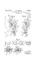
- Figure 1 is a right-hand perspective View of a Sundstrand accounting machine carriage embodying the features of the invention.
- Figure 2 is a, right hand side View of a worksheet guide together with supporting. means therefor.
- Figures 3 and 4 are left hand sectional side elevations taken between two top-edge gages through the carriage, the figures showing the carriage respectively conditioned for 1 typing and frontJeeding.
- Figure 5 is a diagrammatic plan view of topedge gaging means in novel association with worksheet guides.
- Figures 6 and? are sectional planviews of an adjustable top-edge gage respectively being in the process of adjustment and in locked adjustment on a bar.
- a general reference numeral I0 designates the carriage of such machine with the present improvements embodied therein.
- Said carriage comprises two end-walls I I, wherebetween there extends a platen cylinder I2 which by means of a shaft I3 is journaled therein.
- the end-walls II of'the carriage are fast on a usual track member, not shown, for movement of the carriage on a main frame of; the machine to present different writing portions of the platen opposite a set of typebars I4, one of the latter being indicated in Figure 3 in dot-and-dash lines in a raised, printing position.
- a front-feed structure generally designated by the reference numeral I6, and including two widely spaced arms I! which have pivotal support about the center of half pintles I8 that reach inwardly from the opposite carriage walls I I.
- Pins 20 are cooperative with said arms I1 along faces that are concentric with said pintles, in a manner to keep said arms I! in pivotal association with thepintles.
- the entire front-feed structure I6 is normally in an out-of-way position with regard to the operating range of the type-bars I 4, see Figure 3 and also Figure 1.
- the aforesaid front-feed structure I6 includes connecting means between the two arms I 1, comprising, a frame 22 struck up from sheet-metal, having a right hand flange 23 fastened to the right hand arm IT, as at 24, by meansof rivets or otherwise, and having also a left hand flange 26.
- the latter flange is connected by means of several tie-rods 28 with a plate 30 that is rigid with the left hand arm I! of the front-feed structure.
- the two flanges 23 and 26 are integral with a connecting web 32 of angular cross-sec- I tion, together with which they constitute said 1 guide numbered 34.
- Said paper guides 34 are in the form of generally upright channel members 36which are splined for ready adjustment along the rod in a manner that is conventional, and against moderate frictionalresistance.
- brackets 36 there ar two other brackets 38 on the rod 3 3 which have upreaching extensions 40 whereto there ar fastened, as by screws 4
- -Said flatstock bars 42 carry each a top-edge gage-block 44 which is adjustable to different elevations therealong.
- the brackets 38 are adjustable along the rod33 against frictional resistance, "the same as the brackets 36.
- Each gaging block has opposite'walls 45 flanking and extending well to the "rear of the side-edges of the bar-4 2,-a rearface 4'6 ofthe block being normally contacting the front of the bar.
- each bar 42 is provided with a slot '41 extending longitudinally therein. Extending through this slot and fastened to'the gage-block is a shouldered screw 48 having an enlarged head 49. On this screw, between the head 49 and the rear of the bar 42 there is contained a compression spring 50 and a washer said spring providing tension to draw the gageblock 44 resiliently against the front of the bar 42.
- Each gage-block also carries two pins 52 which project'rear-wardly therefrom to provide protuberances for toothed engagement in perforations 53 provided in the bar '42 along both slides of the slot 41. It will thus be seen that the gage-'- blocks 44 are adjustable to different definite locations or elevations along the "bar 42, it being merely required to pull the gage-blocks forwardly,
- gage-blocks 44 project Well forwardly across the plane in which the marginal portions of work-sheets are adapted to be guided by said paper guides 34, They afford underneath thereof a top-edge gaging face '54 which extends forwardly from the supporting bar 42, an which ends in a pronounced downward dip 55 at the front for a purpose to be brought out later,
- the top of the gage-block 44 is downwardly and forwardly sloping as at '5l', for a purpose also yet to be brought out.
- the illustrated chute comprised by the paperguides 34 accommodates a relatively narrow work-sheet, and it will be seen that the supporting sheet-metal frame 22 need only extend partly along the carriage.
- the section of the carriage to the left thereof may accommodate another work-sheet, such as a rear-fed sheet; and in some instances may not be required.
- the frontfeed structure is normally in an eut-of-way position' of the type-bars.
- said front-feed structure is preferably tilted forwardly about the said pintles 18 to said Figure 4'position.
- a detenting link For detenting the front-feed structure in its said two positions, there is connected to the righthand arm I! of said structure a detenting link.
- a work-sheet W to be introduced is'moved downwardly into the channel 7 guides 34 and as the lower portion thereof en-
- the Work-sheet assumes below the gage blocks gradually again a transversely straight condition and finally enters a front-feed throat intermediate a front-feed lip 65 and the platen.
- Figure 4. 'Said front-feed lip pivoted 'inithe opposite carriage endsras at Stand, as shown in Figure..4,'is capableto :direct the vpaper in a flat curve rearwardly underneath the platen.
- the work-sheet is pushed down until its top edge has passed the gaginghlocks. It will 'be noted from the full-line representation of the worksheet W in Figure 5 that the work-sheet'fis contacted by the rear-faces of the forward walls .of the channel guides 34 while. the work-sheet intermediate the plane of said faces is bowed forwardly by the gage blocks; The instant the upper sheet-edge passes the 1 front-apexes .of'jthe gaging blocks, is apparent 11017118 operatorinasmuch as the sheet will then flex'rearwa'rdly to the position indicated in ' Figuredby dot-anddash lines, The work-sheet is then pu'lled up against the gaging faces 54 in close proximity to the bars 52.
- the downward dip 55' of the gaging face '54 thereupon keeps the upper. end of the work-sheet in astraight condition between the two guides 34, in opposition "toa tendency of the work-sheet to flex forward, particularly, when the front-feed structure 316 is restored.
- This lip moving "mechanism comprises a member Blextendihg intermediate the twocarriage ends I l and having pivotal support thereon. From said member 61 there reaches upwardly at'eac'h end of the carriage an arm 68 :to the front of a pin which projects laterally from the adjacent arm I!
- the downward dipping extension 55 of the gaging face 54 is instrumental to keep the work sheet substantially in a straight plane between the two side guides 34, and bent rearwardly of the type-bars I4.
- the described organization of elements is simple, conveniently adjustable for different width forms and line positions, and facilitates introduction and withdrawal of forms at great speed and with utmost accuracy.
- the paper guides 34 and the top-edge gages 44 be part of a displaceable front-feed structure, although its displaceability in certain machines or work is of added value.
- Use of two top-edge gages 44 is advantageous in that it facilitates proper squaring of the work-sheet, but, obviously one gage 44 may be satisfactory in many instances.
- a work-sheet guiding means to facilitate movement of a worksheet to a desired position on the machine, said guiding means comprising guiding surfaces in a common plane, for contacting one face of a worksheet at two laterally spaced locations, worksheet gaging means located intermediate the two laterally spaced guiding surfaces and projecting a short distance across said plane from the side of the plane opposite to that from which the guiding surfaces are contacting said work-sheet, and deflecting means to bow the work-sheet over the projecting gaging means while the work-sheet is being moved toward said desired position with the said guiding surfaces active in guiding the Work-sheet, said gaging means including a face whereagainst to gage the work-sheet in the desired position after moving it past the gaging means.
- means including two spaced channel formations to guide a work-sheet along two lateral, spaced ends in a common plane for movement to a desired position on the machine, work-sheet gaging means located intermediate the two spaced channel formations and projecting from one side across the said common plane, and deflecting means to bow a work-sheet past said projecting gaging means while the work-sheet is being moved toward said desired position with the lateral ends guided in said channels, said gaging means including a face whereagainst to back up and gage the work-sheet in the desired position after moving it past the gaging means.
- a platen In a record preparing machine, a platen, guiding means to present a work-sheet down the front of the platen and in a rearward sweep thereunder, comprising widely spaced members for guiding contact by the front-face of the work-sheet along its side margins, top-edge worksheet gaging means intermediate said guidemembers having support to the rear of said members and having a gaging face projecting forwardly thereof, and a downwardly and forwardly sloping sheet-deflecting face associated with said gaging means to cam or bow the work-sheet intermediate said members forwardly of said topedge gage as it is being presented and guided down the front of the platen, said work-sheet being drawn upwardly against said gaging face after deflecting passage down past the front of said gaging means.
- a platen guiding means to present a work-sheet down the front of the platen and in a rearward sweep thereunder, comprising widely spaced members for guiding contact by the front-face of the work-sheet along its side margins, top-edgeworksheet gaging means intermediate said guidemembers having support to the rear of said members and having a gaging face projecting forwardly thereof and ending in a pronounced downward dip, and a downwardly and forwardly sloping sheet-deflecting face associated with said gaging means to cam or bow the work-sheet intermediate said members forwardly of said topedge gage as it is being presented and guided down the front of the platen, said work-sheet being drawn upwardly against the rear of said gaging face after deflected passage down past the front of said gaging means, and forward I fiexure of the sheet intermediate said guiding members being prevented by the downward dip of the gaging face.
- a platen means to present a work-sheet down the front of the platen and in a rearward sweep thereunder, comprising a front-feed structure displaceable from an out-of-way position above and to the rear of the front-face of the platen to a forward position facilitating front-feeding of the work-sheet, said structure including, two widely spaced means for guiding the work-sheet along its margins, and a top-edge Work-sheet gage intermediate said guiding means, having support to the rear of said guiding means, and having underneath a gaging face projecting forwardly and ending in a pronounced downward dip at the front, said gage including a downwardly and forwardly sloping sheet-deflecting face to bow the work-sheet forwardly as such is front-fed to the platen, the work-sheet being front-fed past said top-edge gage and being backed up against said gaging face, said downward dip being instrumental to move and bend the work-sheet rearwardly as the front-feed structure is restored from forward
- a platen, front-feed means including two spaced means to guide a work-sheet along its margins in a defined plane, a flat-stock bar intermediate said two spaced means, rising contiguous to the rear of said plane above the platen, the bar being provided with a slot extending therealong, a top-edge gage supported on said bar to project forwardly across said plane and having walls facing the front and the two sides of the bar, an element reaching from the gage freely through the said slot in the bar and having an enlargement therebehind spaced from the bar, said element permitting the gage to be raised limitedly off the front of the bar, means to afford a toothed, releasable engagement of said gage with said bar in different locations therealong, and spring means having anchorage on said element and bearing on the back of said bar to press said gage resiliently, but releasably against the front side of the bar, providing thus for adjustment of the gage to different positions along said bar, said gage having a sheet
Landscapes
- Registering Or Overturning Sheets (AREA)
Description
Aug. 12, 1947.
w. A, ANDERSON FRONT FEED MECHANISM FOR WRITING MACHINES Filed June ll, 1946 3 Sheets-Shet 1 INVENTOR v mum A. ANDERSON ATTORNEY Aug. 12, 1947. w. A. ANDERSON 2,425,451
' FRONT FEED MECHANI SM 1 0R WRITING MACHINES 2 Sheets-Sheet 2 Filed Juna 11, 1946 INVENTOR WALTER A. ANDERSON v ATTORNEY Patented Aug. 12, 1947 FRONT FEED MECHANISM FOR WRITING MACHINES Walter A. Anderson, Bridgeport, Conn, assignor to Underwood Corporation, New York, N. Y., a
corporation of Delaware Application June 11, 1946, Serial No. 675,956
This invention relates to record-preparing machines in general, and more particularly to means in such machines to facilitate introduction of work-sheets to predetermined record receiving positions.
In certain accounting systems. it is the practice to prepare at specific time intervals, a single-line account record in'a predetermined line position on a record sheet, such account record giving a summary of the business transacted during the concluded time interval.
After each of said intervals, a new line-entry is made on the recordsheet, upon a succeeding, predetermined line position.
Because record sheets of this nature require repeated handling, they are usually made of relatively firm paper.
It is an object of the instant invention to provide in a record preparing machine, such as an accounting machine, efficient, economical means to facilitate placement of work-sheets for reception thereon of recordings at predetermined positions, for example, to satisfy efficiently the record-making practice outlined hereinabove.
It is another object of the invention to provide in conjunction with means for guiding or feeding work-sheets to a recording station on a machine, eflicient means whereby to locatelthe worksheets at a desired, predetermined record-receiving position.
It is a further object of the invention to provide top-edge sheet-gaging means for work-sheets in eificient cooperative association with guiding means for front-feeding work-sheets to a recordmaking machine, particularly to facilitate expeditious and convenient work-sheet handling.
Another object .is to provide efliciently and con veniently adjustable sheet-gaging means for pcsitioning a work-sheet variably at different record-receiving positions.
With these objects in view, the invention includes certain novel features of construction and combination of elements, the elements of which are set forth in the appended claims, and a preferred form or embodiment of which is hereinafter described with reference to the drawings which accompany and form part of this specification.
Referring now to the drawings:
Figure 1 is a right-hand perspective View of a Sundstrand accounting machine carriage embodying the features of the invention.
Figure 2 is a, right hand side View of a worksheet guide together with supporting. means therefor.
Figures 3 and 4 are left hand sectional side elevations taken between two top-edge gages through the carriage, the figures showing the carriage respectively conditioned for 1 typing and frontJeeding.
6'Claims. (Cl. 197-127) Figure 5 is a diagrammatic plan view of topedge gaging means in novel association with worksheet guides.
Finally, Figures 6 and? are sectional planviews of an adjustable top-edge gage respectively being in the process of adjustment and in locked adjustment on a bar.
The invention has been embodied in the conventionalSundstrand accounting machine, and, directing now attention to the drawings, a general reference numeral I0 designates the carriage of such machine with the present improvements embodied therein. Said carriage comprises two end-walls I I, wherebetween there extends a platen cylinder I2 which by means of a shaft I3 is journaled therein. The end-walls II of'the carriage are fast on a usual track member, not shown, for movement of the carriage on a main frame of; the machine to present different writing portions of the platen opposite a set of typebars I4, one of the latter being indicated in Figure 3 in dot-and-dash lines in a raised, printing position. 1
Upon the end-walls II of the carriage there is mounted a front-feed structure, generally designated by the reference numeral I6, and including two widely spaced arms I! which have pivotal support about the center of half pintles I8 that reach inwardly from the opposite carriage walls I I. Pins 20 are cooperative with said arms I1 along faces that are concentric with said pintles, in a manner to keep said arms I! in pivotal association with thepintles.
The entire front-feed structure I6 is normally in an out-of-way position with regard to the operating range of the type-bars I 4, see Figure 3 and also Figure 1.
The aforesaid front-feed structure I6 includes connecting means between the two arms I 1, comprising, a frame 22 struck up from sheet-metal, having a right hand flange 23 fastened to the right hand arm IT, as at 24, by meansof rivets or otherwise, and having also a left hand flange 26. The latter flange is connected by means of several tie-rods 28 with a plate 30 that is rigid with the left hand arm I! of the front-feed structure. The two flanges 23 and 26 are integral with a connecting web 32 of angular cross-sec- I tion, together with which they constitute said 1 guide numbered 34. Said paper guides 34 are in the form of generally upright channel members 36which are splined for ready adjustment along the rod in a manner that is conventional, and against moderate frictionalresistance.
Intermediate the brackets 36 there ar two other brackets 38 on the rod 3 3 which have upreaching extensions 40 whereto there ar fastened, as by screws 4|, fiat-stock bars '42 torise upwardly therefrom and to double downwardly from points 43 with considerable clearance from the brackets .38, and behind'the work-sheet guiding plane in which the guides 34 lie. -Said flatstock bars 42 carry each a top-edge gage-block 44 which is adjustable to different elevations therealong.
The brackets 38 are adjustable along the rod33 against frictional resistance, "the same as the brackets 36. Each gaging block has opposite'walls 45 flanking and extending well to the "rear of the side-edges of the bar-4 2,-a rearface 4'6 ofthe block being normally contacting the front of the bar. As
clearly seen in Figure 1, each bar 42 is provided with a slot '41 extending longitudinally therein. Extending through this slot and fastened to'the gage-block is a shouldered screw 48 having an enlarged head 49. On this screw, between the head 49 and the rear of the bar 42 there is contained a compression spring 50 and a washer said spring providing tension to draw the gageblock 44 resiliently against the front of the bar 42. Each gage-block also carries two pins 52 which project'rear-wardly therefrom to provide protuberances for toothed engagement in perforations 53 provided in the bar '42 along both slides of the slot 41. It will thus be seen that the gage-'- blocks 44 are adjustable to different definite locations or elevations along the "bar 42, it being merely required to pull the gage-blocks forwardly,
to slide them along the bar, and to allow them.
to locate with reference to-desired pairs of perforations. Th said gage-blocks 44 project Well forwardly across the plane in which the marginal portions of work-sheets are adapted to be guided by said paper guides 34, They afford underneath thereof a top-edge gaging face '54 which extends forwardly from the supporting bar 42, an which ends in a pronounced downward dip 55 at the front for a purpose to be brought out later, The top of the gage-block 44 is downwardly and forwardly sloping as at '5l', for a purpose also yet to be brought out. a i
The illustrated chute comprised by the paperguides 34 accommodates a relatively narrow work-sheet, and it will be seen that the supporting sheet-metal frame 22 need only extend partly along the carriage. The section of the carriage to the left thereof may accommodate another work-sheet, such as a rear-fed sheet; and in some instances may not be required.
As has been stated hereinbefore, the frontfeed structure is normally in an eut-of-way position' of the type-bars. When it is desired to introduce a work-sheet W down the chute comprised by the two paper guides 34, said front-feed structure is preferably tilted forwardly about the said pintles 18 to said Figure 4'position. For detenting the front-feed structure in its said two positions, there is connected to the righthand arm I! of said structure a detenting link.
4 60 having notches 6| for alternate engagement with a roller 62 .on the adjacent end-wall of the carriage, Said detenting dink is under constant downward pressure of a spring 63 to give it yielding detenting action.
Referring to Figure 4, a work-sheet W to be introduced is'moved downwardly into the channel 7 guides 34 and as the lower portion thereof en- The Work-sheet assumes below the gage blocks gradually again a transversely straight condition and finally enters a front-feed throat intermediate a front-feed lip 65 and the platen. See
Figure 4. 'Said front-feed lip pivoted 'inithe opposite carriage endsras at Stand, as shown in Figure..4,'is capableto :direct the vpaper in a flat curve rearwardly underneath the platen.
The work-sheet is pushed down until its top edge has passed the gaginghlocks. It will 'be noted from the full-line representation of the worksheet W in Figure 5 that the work-sheet'fis contacted by the rear-faces of the forward walls .of the channel guides 34 while. the work-sheet intermediate the plane of said faces is bowed forwardly by the gage blocks; The instant the upper sheet-edge passes the 1 front-apexes .of'jthe gaging blocks, is apparent 11017118 operatorinasmuch as the sheet will then flex'rearwa'rdly to the position indicated in 'Figuredby dot-anddash lines, The work-sheet is then pu'lled up against the gaging faces 54 in close proximity to the bars 52. The downward dip 55' of the gaging face '54 thereupon keeps the upper. end of the work-sheet in astraight condition between the two guides 34, in opposition "toa tendency of the work-sheet to flex forward, particularly, when the front-feed structure 316 is restored.
Conventional mechanism is provided to move the front-feed'lip 65 to a closed and open throat position, respectively as the front-feed structure it is moved to its normal out-of-way position of Figure 3, and as it is moved to its front-feed position of Figure 4. This lip moving "mechanism comprises a member Blextendihg intermediate the twocarriage ends I l and having pivotal support thereon. From said member 61 there reaches upwardly at'eac'h end of the carriage an arm 68 :to the front of a pin which projects laterally from the adjacent arm I! of the frontfeed structure; Springs Tl pullin rearwardly on said arms .68, cause the composite structure fil -68, controlled by the pins 10, to swing forwardly and backwardly respectively as the frontfeed structure H5 is moved to the Figure 4 and to the Figure Spositihns. a I
The front-feed lip' 65, under the tension of a spring 'H is constantly urged to assumethe openthroat position seen in Figure 4. However, ears 12, having rigid connection with'the lip 65, are
in controlling'contact with the rear of the arms 68, so that the front-feed, lip will move to the opened and closed throat positions illustrated be bent and bound to the platen around the frontside of the latter.
In the execution of this operation, the downward dipping extension 55 of the gaging face 54 is instrumental to keep the work sheet substantially in a straight plane between the two side guides 34, and bent rearwardly of the type-bars I4.
The described organization of elements is simple, conveniently adjustable for different width forms and line positions, and facilitates introduction and withdrawal of forms at great speed and with utmost accuracy.
It is not essential to the invention that the paper guides 34 and the top-edge gages 44, be part of a displaceable front-feed structure, although its displaceability in certain machines or work is of added value. Use of two top-edge gages 44 is advantageous in that it facilitates proper squaring of the work-sheet, but, obviously one gage 44 may be satisfactory in many instances.
It is to be understood that the invention is susceptible of modification and change without departing from the general purposes and objects of the invention brought out hereinabove.
What is claimed is:
1. In a record preparing machine, a work-sheet guiding means to facilitate movement of a worksheet to a desired position on the machine, said guiding means comprising guiding surfaces in a common plane, for contacting one face of a worksheet at two laterally spaced locations, worksheet gaging means located intermediate the two laterally spaced guiding surfaces and projecting a short distance across said plane from the side of the plane opposite to that from which the guiding surfaces are contacting said work-sheet, and deflecting means to bow the work-sheet over the projecting gaging means while the work-sheet is being moved toward said desired position with the said guiding surfaces active in guiding the Work-sheet, said gaging means including a face whereagainst to gage the work-sheet in the desired position after moving it past the gaging means.
2. In a record preparing machine, means including two spaced channel formations to guide a work-sheet along two lateral, spaced ends in a common plane for movement to a desired position on the machine, work-sheet gaging means located intermediate the two spaced channel formations and projecting from one side across the said common plane, and deflecting means to bow a work-sheet past said projecting gaging means while the work-sheet is being moved toward said desired position with the lateral ends guided in said channels, said gaging means including a face whereagainst to back up and gage the work-sheet in the desired position after moving it past the gaging means.
3. In a record preparing machine, a platen, guiding means to present a work-sheet down the front of the platen and in a rearward sweep thereunder, comprising widely spaced members for guiding contact by the front-face of the work-sheet along its side margins, top-edge worksheet gaging means intermediate said guidemembers having support to the rear of said members and having a gaging face projecting forwardly thereof, and a downwardly and forwardly sloping sheet-deflecting face associated with said gaging means to cam or bow the work-sheet intermediate said members forwardly of said topedge gage as it is being presented and guided down the front of the platen, said work-sheet being drawn upwardly against said gaging face after deflecting passage down past the front of said gaging means.
4. In a record preparing machine, a platen, guiding means to present a work-sheet down the front of the platen and in a rearward sweep thereunder, comprising widely spaced members for guiding contact by the front-face of the work-sheet along its side margins, top-edgeworksheet gaging means intermediate said guidemembers having support to the rear of said members and having a gaging face projecting forwardly thereof and ending in a pronounced downward dip, and a downwardly and forwardly sloping sheet-deflecting face associated with said gaging means to cam or bow the work-sheet intermediate said members forwardly of said topedge gage as it is being presented and guided down the front of the platen, said work-sheet being drawn upwardly against the rear of said gaging face after deflected passage down past the front of said gaging means, and forward I fiexure of the sheet intermediate said guiding members being prevented by the downward dip of the gaging face.
5. In a record preparing machine, a platen, means to present a work-sheet down the front of the platen and in a rearward sweep thereunder, comprising a front-feed structure displaceable from an out-of-way position above and to the rear of the front-face of the platen to a forward position facilitating front-feeding of the work-sheet, said structure including, two widely spaced means for guiding the work-sheet along its margins, and a top-edge Work-sheet gage intermediate said guiding means, having support to the rear of said guiding means, and having underneath a gaging face projecting forwardly and ending in a pronounced downward dip at the front, said gage including a downwardly and forwardly sloping sheet-deflecting face to bow the work-sheet forwardly as such is front-fed to the platen, the work-sheet being front-fed past said top-edge gage and being backed up against said gaging face, said downward dip being instrumental to move and bend the work-sheet rearwardly as the front-feed structure is restored from forward position to its out-of-way position.
6. In a record preparing machine, a platen, front-feed means including two spaced means to guide a work-sheet along its margins in a defined plane, a flat-stock bar intermediate said two spaced means, rising contiguous to the rear of said plane above the platen, the bar being provided with a slot extending therealong, a top-edge gage supported on said bar to project forwardly across said plane and having walls facing the front and the two sides of the bar, an element reaching from the gage freely through the said slot in the bar and having an enlargement therebehind spaced from the bar, said element permitting the gage to be raised limitedly off the front of the bar, means to afford a toothed, releasable engagement of said gage with said bar in different locations therealong, and spring means having anchorage on said element and bearing on the back of said bar to press said gage resiliently, but releasably against the front side of the bar, providing thus for adjustment of the gage to different positions along said bar, said gage having a sheet-deflecting face sloping downwardly from the rear of said plane to the forward extremity of the gage.
WALTER A. ANDERSON.
Priority Applications (1)
| Application Number | Priority Date | Filing Date | Title |
|---|---|---|---|
| US675956A US2425451A (en) | 1946-06-11 | 1946-06-11 | Front feed mechanism for writing machines |
Applications Claiming Priority (1)
| Application Number | Priority Date | Filing Date | Title |
|---|---|---|---|
| US675956A US2425451A (en) | 1946-06-11 | 1946-06-11 | Front feed mechanism for writing machines |
Publications (1)
| Publication Number | Publication Date |
|---|---|
| US2425451A true US2425451A (en) | 1947-08-12 |
Family
ID=24712622
Family Applications (1)
| Application Number | Title | Priority Date | Filing Date |
|---|---|---|---|
| US675956A Expired - Lifetime US2425451A (en) | 1946-06-11 | 1946-06-11 | Front feed mechanism for writing machines |
Country Status (1)
| Country | Link |
|---|---|
| US (1) | US2425451A (en) |
Cited By (3)
| Publication number | Priority date | Publication date | Assignee | Title |
|---|---|---|---|---|
| US2626696A (en) * | 1950-03-10 | 1953-01-27 | Underwood Corp | Front feed paper gauge |
| US2650688A (en) * | 1951-11-02 | 1953-09-01 | Underwood Corp | Paper guide for accounting machines |
| DE3208279A1 (en) * | 1982-03-08 | 1983-04-07 | Josef Dr.med. 8023 Pullach Hammerschmid | Form drawing-in device for electronic printers |
-
1946
- 1946-06-11 US US675956A patent/US2425451A/en not_active Expired - Lifetime
Non-Patent Citations (1)
| Title |
|---|
| None * |
Cited By (3)
| Publication number | Priority date | Publication date | Assignee | Title |
|---|---|---|---|---|
| US2626696A (en) * | 1950-03-10 | 1953-01-27 | Underwood Corp | Front feed paper gauge |
| US2650688A (en) * | 1951-11-02 | 1953-09-01 | Underwood Corp | Paper guide for accounting machines |
| DE3208279A1 (en) * | 1982-03-08 | 1983-04-07 | Josef Dr.med. 8023 Pullach Hammerschmid | Form drawing-in device for electronic printers |
Similar Documents
| Publication | Publication Date | Title |
|---|---|---|
| US2425451A (en) | Front feed mechanism for writing machines | |
| US2563149A (en) | Carbon sheet supporting device | |
| US1874823A (en) | Typewriting machine | |
| US2226151A (en) | Paper carriage for accounting machines | |
| US2131149A (en) | Typewriting machine | |
| US2349693A (en) | Carbon paper support for accounting machines | |
| US1546137A (en) | Typewriting machine | |
| US1501910A (en) | Typewriting machine | |
| US1152856A (en) | Type-writing machine. | |
| US1665285A (en) | Typewriting machine | |
| US2152892A (en) | Typewriting machine | |
| US1853303A (en) | Manifolding device | |
| US1698426A (en) | Typewriting machine | |
| US1668175A (en) | Typewriting machine | |
| US1623445A (en) | Typewriting machine | |
| GB1235549A (en) | Improvements in calculating or business machines | |
| US1487168A (en) | Typewriting machine | |
| US1508810A (en) | Typewriting machine | |
| US712607A (en) | Type-writing machine. | |
| US2537747A (en) | Sheet feeding device | |
| US1497654A (en) | Typewriting machine | |
| US1565936A (en) | Typewriting machine | |
| US1595591A (en) | Typewriting machine | |
| US1586343A (en) | Typewriting machine | |
| US1537455A (en) | Typewriting machine |