US242539A - Brace for vehicle-springs - Google Patents
Brace for vehicle-springs Download PDFInfo
- Publication number
- US242539A US242539A US242539DA US242539A US 242539 A US242539 A US 242539A US 242539D A US242539D A US 242539DA US 242539 A US242539 A US 242539A
- Authority
- US
- United States
- Prior art keywords
- spring
- knuckle
- springs
- brace
- braces
- Prior art date
- Legal status (The legal status is an assumption and is not a legal conclusion. Google has not performed a legal analysis and makes no representation as to the accuracy of the status listed.)
- Expired - Lifetime
Links
Images
Classifications
-
- B—PERFORMING OPERATIONS; TRANSPORTING
- B60—VEHICLES IN GENERAL
- B60G—VEHICLE SUSPENSION ARRANGEMENTS
- B60G11/00—Resilient suspensions characterised by arrangement, location or kind of springs
- B60G11/02—Resilient suspensions characterised by arrangement, location or kind of springs having leaf springs only
- B60G11/08—Resilient suspensions characterised by arrangement, location or kind of springs having leaf springs only arranged substantially transverse to the longitudinal axis of the vehicle
Definitions
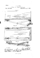
- FIG. is a view of the under side ot' the wagon-box. showing a set of braces, with their adjuncts, asapplied to the springs and running-gear, and Fig. 3 is a perspective view of one of the braces for the hind axle and springs detached.
- My invention contemplates certain improvements in the runnin g-gear of spring wagons or vehicles; and it consists in the combination, with the wagon box or body and its springs, of a system of jointed stays or braces, of which one brace is used for the fifth-wheel and its spring, while two braces are employed (one on each side of the box) for the hind axle and its spring, substantially in the manner and for the purpose hereinafter more fully set forth.
- A represents the wagon box or body, which may be of any desired pattern or construction
- D is the fifth-wheel, which is suitably clipped to the front axle. (Not shown.) Eis thefront spring.
- the jointed stay or brace is composed, essentially, of two parts-viz., a long arm, F, and a short arm, G, which are jointed at H.
- Hinged to the free end of the short 4arm is a knuckle, I, having a projecting lip, i, which is bolted to the under side of the middle top part of the front spring, E.
- rPhe long arm has at one end a knuckle, K, which is bolted to the fth-wheel below the upper knuckle, I, and at the other end of arni F is pivoted a knuckle, L, which is cast with a sleeve, L', in the same longitudinal axis as arm F.
- M is a plate, which is bolted to the under side of box A, and has two downward-projecting lugs, m, between which a rod or pin, N, is iixed-th at is, inserted through the sleeve L- and which is ot' such a length that the sleeve, with its knuckle, can play freely forward and back between the lugs or stops m m.
- Thejoint or knuckle L at the upper end o'f F is in a line with the knuckle I at the upper end ot' G, as shown in Fig. 1.
- rlhe two braces for the hind axle and its spring are constructed and arranged in substantially the same way, with the exception that a knuckle, O, of the shape shown in Fig.3 is substitutedfor the knuckle K.
- rlhe knuckle O has two projections, a b, at right angles to one another, and is clipped to the axle through holes made in said projections or lips.
- TheV constructed with a sliding knuckle, L L', and
- the hind axle may be further braced by rods extending ⁇ from the central knuckle or joint, H, of each ofthe side braces, F G,out to opposite ends of the axle, to which they are secured close to the hubs, in which case these rods would answer the same purpose as the hounds or vbraces on a perch.
- the plate M is bolted to the under side of the box and the short arm G is bolted to the under side of the top part of the spring byits knuckle, which may be made to suit the elevation of the box.
- the lower end of arm F is bolted by its knuckle to the top side of the under part of the spring.
- the knuckles to be shaped in all cases to suit the elevation of the wagon-box.
- jointed brace F G having at one end of its long arm F the tfth-wheel D, and at the opposite or upper end of said arm the longitudinallyperforated hinged sleeve L and knuckle L, as shown and specified, for the purpose set forth.
Landscapes
- Engineering & Computer Science (AREA)
- Mechanical Engineering (AREA)
- Springs (AREA)
Description
(Model.)
J. R. HULL. Brace for Vehicle Springs. No.. 242,539. Paented J-une 7, i881.
/ Tum .u
Qrllll] .l 1 l 7. um
N. PETERS, Pnulwumgnplm. whingm. D. c.
liTieD STATES PATENT OFFICEa JOHN R. HULL, OF SPRING HOPE, PENNSYLVANIA.
BRACE FOR VEHICLE-SPRINGS.
SPECIFICATION forming part of Letters Patent No. 242,539, dated June 7, 1881.
Application filed April 4, 188]. (Model.) I
lowing is a full, clear, and exact description 1 oftheinventiomwhich will enableothers skilled in the art to which it appertains to make and use the same, reference being had to the accompanying drawings, which form a part of this specification, and in which- Figure lis alongitudinal vertical section of the front part of the box and part ot' th e running-gear ot' a spring-\vagon, showing my iinproved brace as applied to the fifth-wheel. Fig. is a view of the under side ot' the wagon-box. showing a set of braces, with their adjuncts, asapplied to the springs and running-gear, and Fig. 3 is a perspective view of one of the braces for the hind axle and springs detached.
Similar letters of reference indicate corresponding parts in all the tigures.
My invention contemplates certain improvements in the runnin g-gear of spring wagons or vehicles; and it consists in the combination, with the wagon box or body and its springs, of a system of jointed stays or braces, of which one brace is used for the fifth-wheel and its spring, while two braces are employed (one on each side of the box) for the hind axle and its spring, substantially in the manner and for the purpose hereinafter more fully set forth.
In the annexed drawings, A represents the wagon box or body, which may be of any desired pattern or construction, and D is the fifth-wheel, which is suitably clipped to the front axle. (Not shown.) Eis thefront spring.
The jointed stay or brace is composed, essentially, of two parts-viz., a long arm, F, and a short arm, G, which are jointed at H. Hinged to the free end of the short 4arm is a knuckle, I, having a projecting lip, i, which is bolted to the under side of the middle top part of the front spring, E. rPhe long arm has at one end a knuckle, K, which is bolted to the fth-wheel below the upper knuckle, I, and at the other end of arni F is pivoted a knuckle, L, which is cast with a sleeve, L', in the same longitudinal axis as arm F.
M is a plate, which is bolted to the under side of box A, and has two downward-projecting lugs, m, between which a rod or pin, N, is iixed-th at is, inserted through the sleeve L- and which is ot' such a length that the sleeve, with its knuckle, can play freely forward and back between the lugs or stops m m.
Thejoint or knuckle L at the upper end o'f F is in a line with the knuckle I at the upper end ot' G, as shown in Fig. 1.
rlhe two braces for the hind axle and its spring are constructed and arranged in substantially the same way, with the exception that a knuckle, O, of the shape shown in Fig.3 is substitutedfor the knuckle K. rlhe knuckle O has two projections, a b, at right angles to one another, and is clipped to the axle through holes made in said projections or lips. TheV constructed with a sliding knuckle, L L', and
plate M, precisely as the front brace. There are two hind braces, one at each end of spring P, as shown in Fig. 2, and their plates M are, ofcourse, bolted to opposite sides ofthe wagon-box, in a line with the middle plate. If desired, the hind axle may be further braced by rods extending` from the central knuckle or joint, H, of each ofthe side braces, F G,out to opposite ends of the axle, to which they are secured close to the hubs, in which case these rods would answer the same purpose as the hounds or vbraces on a perch.
Where a perch is used, as 011 a spring-buggy, the plate M is bolted to the under side of the box and the short arm G is bolted to the under side of the top part of the spring byits knuckle, which may be made to suit the elevation of the box. rIhe lower end of arm F is bolted by its knuckle to the top side of the under part of the spring.
structed of malleable strap-iron, wrought-iron,
-cast-iron, or any other suitable material, and
of any desired dimensions, the knuckles to be shaped in all cases to suit the elevation of the wagon-box.
IOO
From the foregoing description, taken in connection with the drawings, it will readily be seen that these jointed. stays or braces prevent tipping or tilting ot' the springs E and P for. ward or back, so that each spring will work in a true vertical plane. It will further be seen that the play of the spring up and down is limited by the play of the sliding sleeve L Ll upon piu N between its stops m m, thus avoiding breakage by too great au upward strain on the springs. Again, it gives pliability and elasticity to the whole running-gear, reduces the cost of ironing a buggy or other springvehicle, and cau be easily applied and again removed when desired. All joints or knuckles should be so constructed as to exclude dirt and dust, so that they may work smoothly and easily at all times.
Having thus described my invention, I do not claim, broadly, the combination, with a spring-supported wa gon-bed and its springs, of jointed stays or braces adapted to slide in bearings atixed to the under side of the bed; but
I claim as my improvement and desire to secure by Letters Patentof the United States- Thecombination of the wagon-bedA, having the fixed plate M, provided with the stops m m and their connecting-pin N, springE, and
jointed brace F G, having at one end of its long arm F the tfth-wheel D, and at the opposite or upper end of said arm the longitudinallyperforated hinged sleeve L and knuckle L, as shown and specified, for the purpose set forth.
2. The combination, with the wagon-bed A, provided with a front spring, E, and hind spring, P, of a jointed front brace, F G, the long arm F ot' which is connected at one end by its knuckle K to the fifth-wheel D, and at its opposite or upper end to the knuckle L and sleeve L and two jointed hind braces arranged at opposite ends of the hind Spring, P, the inner ends ot' the said three sets of jointed braces sliding by their hinged sleeves L upon their respective bearings M N between the stops m m, one ot' said bearings or bearing-plates being in the middle line of the wagon-bed and the other two on opposite sides of the sanne, substantially as and for the purpose herein shown and described.
In testimony that I claim the foregoing as my own I have hereto aflixed my signature in presence of two witnesses.
JOHN R. HULL. Witnesses:
J EREMIAH GORDON, JAMES L. NORTON.
Publications (1)
| Publication Number | Publication Date |
|---|---|
| US242539A true US242539A (en) | 1881-06-07 |
Family
ID=2311873
Family Applications (1)
| Application Number | Title | Priority Date | Filing Date |
|---|---|---|---|
| US242539D Expired - Lifetime US242539A (en) | Brace for vehicle-springs |
Country Status (1)
| Country | Link |
|---|---|
| US (1) | US242539A (en) |
-
0
- US US242539D patent/US242539A/en not_active Expired - Lifetime
Similar Documents
| Publication | Publication Date | Title |
|---|---|---|
| US242539A (en) | Brace for vehicle-springs | |
| US243436A (en) | Oscillating vehicle-gear | |
| US471007A (en) | Vehicle running-gear | |
| US304155A (en) | Chaeles wesley allen | |
| US155023A (en) | Improvement in running-gears for vehicles | |
| US239452A (en) | Spring-brace for vehicles | |
| US300254A (en) | Peteb hebeet | |
| US226540A (en) | Vehicle-spring | |
| US144323A (en) | Improvement in king-bolts for vehicles | |
| US465992A (en) | Vehicle-spring | |
| US197689A (en) | Improvement in carriage-springs | |
| US346341A (en) | Road-wagon | |
| US939158A (en) | Trackless power-driven vehicle. | |
| US148118A (en) | Improvement in running-gears | |
| US273599A (en) | Geae for wagois | |
| US376079A (en) | Paul emeey | |
| US1094492A (en) | Running-gear. | |
| US660608A (en) | Low-down short-turn gear for vehicles. | |
| US200712A (en) | Improvement in fifth-wheels for carriages | |
| US726146A (en) | Vehicle-coupling. | |
| US740051A (en) | Vehicle. | |
| US187694A (en) | Improvement in vehicle-gearing | |
| US451029A (en) | Two-wheeled vehicle | |
| US413888A (en) | Wag on-gear | |
| US502609A (en) | Running-gear for wagons |