US2425366A - Pointer return device - Google Patents
Pointer return device Download PDFInfo
- Publication number
- US2425366A US2425366A US681796A US68179646A US2425366A US 2425366 A US2425366 A US 2425366A US 681796 A US681796 A US 681796A US 68179646 A US68179646 A US 68179646A US 2425366 A US2425366 A US 2425366A
- Authority
- US
- United States
- Prior art keywords
- rotor
- coil
- magnet
- return
- balancing
- Prior art date
- Legal status (The legal status is an assumption and is not a legal conclusion. Google has not performed a legal analysis and makes no representation as to the accuracy of the status listed.)
- Expired - Lifetime
Links
Images

Classifications
-
- G—PHYSICS
- G08—SIGNALLING
- G08C—TRANSMISSION SYSTEMS FOR MEASURED VALUES, CONTROL OR SIMILAR SIGNALS
- G08C19/00—Electric signal transmission systems
- G08C19/38—Electric signal transmission systems using dynamo-electric devices
- G08C19/40—Electric signal transmission systems using dynamo-electric devices of which only the rotor or the stator carries a winding to which a signal is applied, e.g. using step motor
- G08C19/42—Electric signal transmission systems using dynamo-electric devices of which only the rotor or the stator carries a winding to which a signal is applied, e.g. using step motor having three stator poles
-
- G—PHYSICS
- G01—MEASURING; TESTING
- G01R—MEASURING ELECTRIC VARIABLES; MEASURING MAGNETIC VARIABLES
- G01R27/00—Arrangements for measuring resistance, reactance, impedance, or electric characteristics derived therefrom
- G01R27/02—Measuring real or complex resistance, reactance, impedance, or other two-pole characteristics derived therefrom, e.g. time constant
- G01R27/08—Measuring resistance by measuring both voltage and current
- G01R27/10—Measuring resistance by measuring both voltage and current using two-coil or crossed-coil instruments forming quotient
- G01R27/12—Measuring resistance by measuring both voltage and current using two-coil or crossed-coil instruments forming quotient using hand generators, e.g. meggers
Definitions
- This invention relates to measuring and/or control devices of the type comprising a magnet rotor, the position of which is controlled by control means which in turn are controlled by any suitable means such as a variable physical magnitude.
- the control means controlling the rotor position may be constituted by a plurality of deflecting coils positioned about the rotor and connected to be dif Schl-tially energized, the differential energization of the deflecting coils being controlled by the variable physical magnitude to be supervised.
- the coactlon between the rotor including an iron rotor which is magnetized temporarily by a coil during each cycle of the alternating current.
- Such rotor return devices generally consist oi/a stationary permanent magnet placed closely adjacent to the rotor assembly.
- the magnetic fields of the return magnet and of the rotor then coact in such manner that the pole of the return magnet close to the rotor will attract the pole of the rotor having opposite polarity.
- the rotor will be turned into a definite position relative to the position of the return magnet.
- the position of the stationary return magnet is selected so that the angular position in which the rotor is placed thereby, is the desired off-scale position of the rotor.
- the return magnet being a permanent magnet
- the return magnet will exert its influence upon the rotor position not only when the instrument is not in operation and when it is desirable to return the rotor into the zero position but also when the instrument is energized for indication or control.
- the rotor position during the operation of the instrument is a function not only of the control means but also of the field of the return magnet. Consequently, the rotor position does not correctly reflect the variable physical magnitude or other force controlling the said control means. In other words, the indications or control actions of the instrument will be not quite accurate.
- One object of the invention is a novel and improved rotor return device which will place the rotor in a predetermined neutral position when the instrument is not operating.
- Another object of the invention is a novel and improved return device which will return the rotor into a predetermined neutral or zero position when the instrument is not in operation but will not afiect the rotor position to any appreciable extent when the instrument is in operation so that the rotor position is always a true function of the magnitude controlling the rotor position.
- Another object of the invention is a novel and improved return device which is insensitive to voltage changes of the electrical supply feeding the circuit of the measuring and control device.
- a balancing coil energized by a constant current supply ior setting up a field which substantially balances the magnetic field of the return magnet during the operation of the measuring and control device.
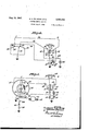
- Fig. 1 is a diagrammatic plan view of an instrument of the ratiometer type equipped with a rotor return device according to the invention.
- Fig. 2 shows a modification of the rotor return device in conjunction with the same ratiometer as ha been illustrated in Fig. 1.
- Fig.3 is a circuit diagram showing a voltage regulator for a rotor return device the invention.
- Fig. 4 shows a typical circuit diagram of a ratiometer equipped with a rotor return device according to the invention and of a transmitter according to controlling the ratiometer, and
- a pointer is also supported on shaft II or on the rotor body itself and cooperates with a stationary scale 7 .l3 to indicate the angular position of the rotor.
- the scale may be calibrated in units of a variable physical magnitude to be supervised, for instance, in gallons or pounds of fuel.
- Three deflecting coils ll, I5 and i6 are stationarily mounted about the rotor assembly, uniformly spaced. The deflecting coils are connected to be differentially energized and are employed for turning the rotor assembly and hence the pointer into the desired position, the differential energization of the coils being controlled by the variable physical magnitude to be supervised as will be more fully'explained hereinafter.
- a permanent stationary magnet I1 is mounted in a suitable position relative to the rotor, preferably concentric with the rotor axis opposite to the top or bottomside of the rotor. The poles of magnet I!
- This coil is shown'in Fig. l as being structurally combined with coil l6. However, it should be understood that the coil can also be mounted in any other suitable position; It is only essential that the balancing coil-is positioned-in relation to the return magnet in such. a manner that it interacts with the magnet rotor similarly --as the retu'rn'm'agnet interacts with the'magnet rotor but opposite in direction. Then, if a steady current'ofproper polarity and magnitude is passed, through the balancing coil the flux therefrom will substantially balance the flux from the pointer return magnet insofar as the influence of the latter upon the magnet rotor is con- Fig.
- Fig. 2 shows a balancing coil 18' which is mounted separately from coil l6. As will be seen from above and below the top and the bottom of the rotor. Practical tests have shown that under certain conditions such enlarged coil is advantageous.
- FIG. 3 shows a typical circuit diagram to which the invention is applicable.
- a source of electricity 20 supplies a measuring and control device such as shown in Figs. 1 and 2 and the control there;
- the device and its control circuit are indicated by a rectangle generally designated 2
- the circuit may be a circuit well known as D.-C. Selsyn circui or any other type of ratiometer circuit.
- the balancing coil l8 (or I8) is connected to the circuit through a voltage regulator network generally designated 22.
- This voltage regulator may be of any suitable type.
- Fig. 3 shows a regulator comprising two non-linear resistance elements 23, 23' such as selenium rectifier discs and two linear variable-resistance elements 24, 24 connected into a bridge with like elements opposite each other. The bridge is supplied with direct current at opposite terminals 25, 25', preferably through a series resistor 26.
- the remaining two terminals 21, 21 of the bridge supply direct current to the balancing coil ID.
- the bridge is operated with a range of voltages so selected that it will regulate its outputthroughout the entire range of voltages.
- balancing coil 18 receives substantially constant current throughout the entire range of voltages received by the bridge at terminals 25, 25.
- the voltage supplied to the bridge may come directly from the source of current 20 or from any available part .of the ratiometer circuit generally designated 2
- the current supplied to balancing coil i8 is adjusted, preferably by varying the resistance elements 24, Zluntil the flux from coil 18 Just balances the flux from the permanent return magnet i
- a Voltage'regulator has the advantage that in spite of voltage variations of the supply 20 aconstant current is s plied to balancing coil l8 so that this coil willcontinuous 1y balance the influence ofthe return magnet on the rotorposition, as long as coil 18 is energized.
- the employment of a, voltage regulator permits also deriving current for the balancing coil from a portion of the ratiometer circuit in which the available currentmay vary with the variations of the magnitude. to be supervised.
- Fig. 4 shows a circuit diagram of this type.
- a transmitter generally designated T controls a ratiometer generally designated R.
- the transmitter may be of any suitable type.
- a conventional transmitter of the so-called "resistance type comprising a resistance element 30 which is engaged by a grounded slider contact 3
- the position of the slider contact relative to resistance element 30 is controlled by any suitable means, for instance,
- Theend taps and theintermediate taps are connected by wires 36.31 and Fig'. 2 the axis of the coil coincides with a radial the poles of the return magnet.
- the diameter of the coil is so selected that the coil extends 38 respectively, to one terminal of the ratiometer" coils M, 1-5 and l6,-the.. other terminals. of the ratiometer coils being-joined by. a: common, wire 39.
- the terminals of the ratiometercoilsconnected to wires 36, 31 and 38 are also connected to one terminal of resistors 40, 41, 42.
- the other 5 terminals or the resistors are Joined at point-43 and connected through a switch 44 to the plus terminal of a battery 45, theother terminal of the battery being grounded thereby closing the circuit to slide contact 3 I.
- on resistance element 30 controls the distribution of current through the ratiometer coils and hence the angular position of rotor l and with it the position of pointer 12. Consequently, the positionof pointer I2 will be a function of the position of slider 3
- the ratiometer is not measur ing, that is, when switch 44 is open, return magnet will return pointer [.2 into its off-scale position.
- the balancing coil 3 (or iii) serving to balance the influence of return magnet i'i during operation is shunted by an adjustable resistor 50 which serves to adjust the fiux from coil I8 until it just balances the flux from return magnet H.
- resistor '50 corresponds to resistance element 24, 24 of Fig. 3.
- Coil l8 and resistor 50 are grounded at one end and connected at the other end by a wire -5land a resistor 52 to point 43.
- Resistor 52 is a resistor of a type compensating for voltage variations, thereby maintaining a constant current to coil l8.
- resistor 52 may consist of a constantcurrent filament made of ironwire in an atmosphere of hydrogen, whereby temperature and resistance of the filament change with the applied voltage.
- coil i8 is energized, thereby balancing the influence of return magnet i! when switch 44 is closed and the system is in operation, and will be deenergized when switch system of Fig.
- the transmitter comprises an annular resistance element 55 tapped at three equi-distant points 55, 51 and 58. These taps are connected to the outer terminals or rat'iometer coils i4, i5 and. I5. Resistance element '55 is slidably engaged by two diametrically opposite sliders. '59 and 59' supported on a rotatably mounted insulation disc 60.
- sliders 58, 59 is controlled by the variable physical magnitude to 'be supervised.
- the disc position is controlled by meansof a float 6
- Slider 59 is grounded by a wire 53 and slider 59' is connected by a wire'M, switch 44 and a resistor 55 to the plus terminal oi! battery 45.
- the position of sliders '59, 59' relative to resistance element 55 will control the differential energization of the ratiometer coils and hence also the positions of the rotor i0 and pointer i2.
- the circuit of the balancing coil la is the same as has been described in connection with Fig. 5 with the exception that wire 5! now connects the one terminalof resistor 52 to wire 39 joining the ratiometer coils.
- coil ill will balance the influence of return magnet II as long asv switch 44 is closed and the system is in operation.
- a magnet rotor in combination a magnet rotor, control means for controlling the angular position of saidrotor, indicating and control means controlled by the rotor position, magnetic means constructed and positioned to urge the rotor into a predetermined angular position, a coil included in a circuit with a source of current and positioned to produce a field balancing the influence of the magnetic means on the rotor position, volt- ,age regulating means connected with said circuit for supplying constant current to the balancing-coil independently of voltage variations of the source of current, and means for deenergizing the balancing coil.
- said control means is rendered inoperative for the purposes aforesaid, thereby controlling the rotor position by the magnetic means only.
- a magnetic rotor a plurality of deflecting coils magnetically coacting with the rotor and connectedto'be differentially energized
- a transmitter controlled by a change of a variable physical magnitude to be supervised'included in acircuit with the deflecting coils and a source of current for controlling the differential energization of the deflecting coils
- indicating and'control means controlled by the rotor position a stationary permanent magnet positioned to urge the rotor into a predetermined angular position
- a balancing coil included in a second circuit connected to the first circuit and positioned to produce a field balancing the influence of the permanent magnet on the rotor position
- voltage regulating means included'ln the second circuit for supplying constant current to' the balancing coil independently of voltage variations of said source of current, and means for deenergizing said balancing coil and said deflecting coils, thereby controlling the-rotor position by the magnetic field of the permanent
- a measuring and controldevice in combination a rotatably supported magnet rotor, electric control means for controlling the angular position of said rotor, indicating and control means controlled by the rotor position, permanent magnet means constructed and positioned to urge the rotor into a predetermined angular position, a coil included in an impulsing circuit for producing a field balancing the influence.
- the axis of said coil being positioned to substantially coincide with a radial line perpendicularly' extended from the rotor axis and substantially, Parallel to the line connecting the poles of the magnet means, and means for de 7 energizing said coil, when said control means is rendered inoperative for the purposes aforesaid, thereby controlling the rotor position by the magnet means only.
- a magnet rotor a plurality of deflecting coils magnetically coacting with the rotor and connected to be difl'erentially energized
- a transmitter controlled by a change of a variable physical magnitude to be supervised included in a circuit with the deflecting coils and a source of current for controlling the diflerential energization of the deflecting coils
- indicating and control means controlled by the rotor position
- a stationary permanent magnet positioned to urge the rotor into a predetermined angular position
- a balancing coil included in a second circuit connected to the first circuit and'positioned to produce a field balancing the influence of the permanent magnet on the rotor position, the axis oi!
- the said coil being positioned to substantially coincide with a radial line perpendicularly extended from the rotor axis and substantially parble physical magnitude to be supervised included in a circuit with the deflecting coils and a source of current for controlling the differential energization of the deflecting coils, indicating and control means controlled by the rotor position, a stationary permanent ma net positioned to urge the rotor into a predetermined angular position, a balancing coil included in a second circuit connected to the first circuit, and positioned to produce a field balancing the influence of the permanent magnet on the rotor position, the'axis of the said coil being positioned to substantially coincide with a radial line perpendicularly extended from the rotor axis and substantially parallel to the line connecting the poles of the permanent magnet, said balancing coil being structurally combined with one of the deflecting coils, and means for deenergizing said balancing coil and said deflecting coils, thereby controlling the rotor position by the
- the axis of the said coil being positioned to substantially coincide with a radial line perpendicularly ex- -tended from the rotor axis and substantiall par.
- said balancing coil being mounted closely adjacent to one 01' the deflecting coils and having a diameter extending above and below the top and the bottom of said rotor, and means for deenergizing said balancing coil and said deflecting coils, thereby controlling the rotor position by the magnetic field of the permanent magnet only.
- the axis of the said coil being positioned to substantially coincide with a radial line perpendicularly extended from the rotor axis and substantially parallel to the line connecting the poles of the permanent magnet, voltage regulating means included in the second circuit for supplying constant current to the balancing coil independently of voltage variations of said source of current,
Landscapes
- Physics & Mathematics (AREA)
- General Physics & Mathematics (AREA)
- Measurement Of Length, Angles, Or The Like Using Electric Or Magnetic Means (AREA)
- Brushless Motors (AREA)
Priority Applications (3)
| Application Number | Priority Date | Filing Date | Title |
|---|---|---|---|
| US681796A US2425366A (en) | 1946-07-08 | 1946-07-08 | Pointer return device |
| GB31197/46A GB628834A (en) | 1946-07-08 | 1946-10-21 | Improvements in or relating to electrical measuring and control devices |
| FR935566D FR935566A (fr) | 1946-07-08 | 1946-11-04 | Perfectionnements aux dispositifs électriques de mesure et de commande |
Applications Claiming Priority (1)
| Application Number | Priority Date | Filing Date | Title |
|---|---|---|---|
| US681796A US2425366A (en) | 1946-07-08 | 1946-07-08 | Pointer return device |
Publications (1)
| Publication Number | Publication Date |
|---|---|
| US2425366A true US2425366A (en) | 1947-08-12 |
Family
ID=24736853
Family Applications (1)
| Application Number | Title | Priority Date | Filing Date |
|---|---|---|---|
| US681796A Expired - Lifetime US2425366A (en) | 1946-07-08 | 1946-07-08 | Pointer return device |
Country Status (3)
| Country | Link |
|---|---|
| US (1) | US2425366A (fr) |
| FR (1) | FR935566A (fr) |
| GB (1) | GB628834A (fr) |
Cited By (3)
| Publication number | Priority date | Publication date | Assignee | Title |
|---|---|---|---|---|
| US2798200A (en) * | 1953-04-03 | 1957-07-02 | Gen Electric | Long-scale ratio instrument |
| US3302191A (en) * | 1964-05-04 | 1967-01-31 | Gen Motors Corp | Gauge circuit |
| US4758784A (en) * | 1985-11-15 | 1988-07-19 | Stewart Warner Corporation | Air core gauge with zero pointer return related application |
Families Citing this family (1)
| Publication number | Priority date | Publication date | Assignee | Title |
|---|---|---|---|---|
| USRE32604E (en) * | 1981-06-22 | 1988-02-16 | Beede Electrical Instrument Co., Inc. | Electric indicator with return-to-zero feature and compensating coil to cancel the return-to-zero feature during measurement |
-
1946
- 1946-07-08 US US681796A patent/US2425366A/en not_active Expired - Lifetime
- 1946-10-21 GB GB31197/46A patent/GB628834A/en not_active Expired
- 1946-11-04 FR FR935566D patent/FR935566A/fr not_active Expired
Non-Patent Citations (1)
| Title |
|---|
| None * |
Cited By (3)
| Publication number | Priority date | Publication date | Assignee | Title |
|---|---|---|---|---|
| US2798200A (en) * | 1953-04-03 | 1957-07-02 | Gen Electric | Long-scale ratio instrument |
| US3302191A (en) * | 1964-05-04 | 1967-01-31 | Gen Motors Corp | Gauge circuit |
| US4758784A (en) * | 1985-11-15 | 1988-07-19 | Stewart Warner Corporation | Air core gauge with zero pointer return related application |
Also Published As
| Publication number | Publication date |
|---|---|
| FR935566A (fr) | 1948-06-23 |
| GB628834A (en) | 1949-09-06 |
Similar Documents
| Publication | Publication Date | Title |
|---|---|---|
| US2420539A (en) | Measuring and controlling system | |
| US2050629A (en) | Electric telemetering system | |
| US2112682A (en) | Measuring and controlling system | |
| US2317807A (en) | Telemetric system | |
| US2358103A (en) | Measuring apparatus | |
| US2688253A (en) | Pressure differential responsive device | |
| US2368701A (en) | Galvanometer | |
| US1993527A (en) | Fluid measuring system | |
| US2330427A (en) | Telemetric control system | |
| US2348177A (en) | Measuring and control apparatus | |
| US2425366A (en) | Pointer return device | |
| US2213357A (en) | Direction indicating means | |
| US2196809A (en) | Telemetric system | |
| US2459081A (en) | Electrical measuring instrument | |
| US1768553A (en) | Electrically-operated flow meter | |
| US2050446A (en) | Phenomenon indicating device | |
| US2276506A (en) | Measuring and control apparatus | |
| US2528336A (en) | Relay system | |
| US2118248A (en) | Hydraulic governor | |
| US2569697A (en) | Reversible motor control apparatus | |
| US2097226A (en) | Electric meter | |
| US1774673A (en) | System for the regulation of machines | |
| US2689339A (en) | Control system | |
| US2383942A (en) | Automatic electrical control means | |
| US1964228A (en) | Vernier telemetric system |