US2425362A - Unloading apparatus - Google Patents
Unloading apparatus Download PDFInfo
- Publication number
- US2425362A US2425362A US558008A US55800844A US2425362A US 2425362 A US2425362 A US 2425362A US 558008 A US558008 A US 558008A US 55800844 A US55800844 A US 55800844A US 2425362 A US2425362 A US 2425362A
- Authority
- US
- United States
- Prior art keywords
- die
- plate
- casting
- switch
- conveyor
- Prior art date
- Legal status (The legal status is an assumption and is not a legal conclusion. Google has not performed a legal analysis and makes no representation as to the accuracy of the status listed.)
- Expired - Lifetime
Links
- 238000005266 casting Methods 0.000 description 29
- 238000004512 die casting Methods 0.000 description 20
- 239000012530 fluid Substances 0.000 description 14
- 230000000977 initiatory effect Effects 0.000 description 4
- 230000002441 reversible effect Effects 0.000 description 3
- 238000013459 approach Methods 0.000 description 2
- ZPEZUAAEBBHXBT-WCCKRBBISA-N (2s)-2-amino-3-methylbutanoic acid;2-amino-3-methylbutanoic acid Chemical compound CC(C)C(N)C(O)=O.CC(C)[C@H](N)C(O)=O ZPEZUAAEBBHXBT-WCCKRBBISA-N 0.000 description 1
- 244000061600 Laurocerasus officinalis Species 0.000 description 1
- 244000261422 Lysimachia clethroides Species 0.000 description 1
- 238000010586 diagram Methods 0.000 description 1
- 230000000694 effects Effects 0.000 description 1
Images


Classifications
-
- B—PERFORMING OPERATIONS; TRANSPORTING
- B22—CASTING; POWDER METALLURGY
- B22D—CASTING OF METALS; CASTING OF OTHER SUBSTANCES BY THE SAME PROCESSES OR DEVICES
- B22D17/00—Pressure die casting or injection die casting, i.e. casting in which the metal is forced into a mould under high pressure
- B22D17/20—Accessories: Details
- B22D17/2084—Manipulating or transferring devices for evacuating cast pieces
Definitions
- a main support plate for carrying a framework on which a stripping mechanism is mounted for movement into engagement with a die cast part which has adhered to the knockout pins of the die casting apparatus.
- a stripping mechanism is mounted for movement into engagement with a die cast part which has adhered to the knockout pins of the die casting apparatus.
- Adjustably mounted with respect to the stripper mechanism tially along the line 55 of Fig. 3 in the direction of the arrows;
- Fig. 6 is a schematic diagram of a control circuit for synchronizing the operation of the various parts of the unloading apparatus with each other and with the die casting machine.
- the die casting machine is provided with a base frame ID, from which extend upwardly a pair of side walls II and I2 for supporting a die operand carried by the mounting plate is a framework for supporting a transfer conveyor which is adapted to move into position between the dies of the die casting apparatus to receive a die casting stripped from the upper die of the casting machine either by the knockout pins or by the ati-ng cylinder l3 in a position to support and actuate a piston rod l5 carrying a die actuating block it.
- the die actuating block l6 has a central cavity I'l, the lower end of which is substantially closed by aplaten l8.
- a knockout pin actuating plate l9 having guide pins 26-20 fixed to .it and slidable in suitable apertures formed in the die actuating block IS.
- the knockout pin actuating plate [9 carries actuator pins 2l--2.l, on the lower end of which .there is mounted a plate 22.
- the plate 22 is slidable in a die block 23 and carries knockout pins 24-24 in suitable apertures in an upper die 25, which is fixed to the die block 23 in any suitof the various movable parts with the operation of the die casting machine.
- Fig. l is a fragmentary front elevational View of a die casting machine having an unloading apparatus embodying the present invention mounted thereon;
- Figs. 2 and 3 are fragmentary vertical sectional views taken substantially along the line 22 of Fig. 1 in the direction of the arrows and showing the dies of the die casting machine in their closed and open positions, respectively, and also showing the unloading apparatus in its unoperated'and partially operated positions;
- Fig. 4 is a fragmentary detail View also taken along the line 2-2 of Fig. 1 and showing the stripping mechanism in its completely operated position;
- Fig. 5 is a plan sectional View taken substanable manner.
- a lower die 25 Positioned in direct vertical alignment beneath the upper die 25 is a lower die 25 having an entrance gate 21 aligned with a nozzle 28, which is,
- the mechanism described thus far comprises a conventional, vertical type die casting machine with which the apparatus of the present invention is designed to cooperate. It will be understood that any suitable die casting machine may be equipped with the unloading device of the present invention and that details of the die casting machine of themselves are not pertinent to the present invention except insofar as they cooperate with the specific embodiment of the invention'to be described in detail hereinafter.
- the front face of the side wall It is tapped to receive a pair of machine screws 40-40, which are adapted to pass through slots lk-4
- the lower end of the pintle rod 43 has a conical seat 46 formed in it for receiving the tapered tip of a pivot screw 41, which is threaded. into a boss 48 fixed n the base I8 and which is locked in place by a locking nut 49.
- the framework supporting plate 42 may be adjusted vertically with respect to the die casting machine and, when adjusted, may be locked in place thereon by means of the machine screws 48-48 and that the framework supporting plate 42, upon removal of the screws 48, may be swung out of position 0n the front of the die casting machine to make the dies and other parts of the die casting machine readily accessible.
- a pair of side frame members 58 Formed integrally with or suitably secured to the front face of the plate42 are a pair of side frame members 58 and whichare connected at their outer or forward ends by across brace
- . have rail plates 53 and 54, respectively; secured to them in which there are formed a pair of slots will be moved downwardly to the dot and dash position, as shown in Fig. 3, to strip a casting from the knockout pins 24.
- in cooperation with the framework supporting plate 42, adjustably support a conveyor frame I 8
- the shaft'51 has a pair of levers 59 and 68 attached to it and the shaft 58 has a pair of levers 6
- the shaft 58 also has a lever 63. fixed to it; to which there is attached a contractile spring 64 having its opposite end attached to a cross brace 65.
- the crossbrace 65 serves to interconnect the forwarder leftehand end (Figs.
- the back/plate 68 has attached to it a piston ,rod 69, whichis adapted to be actuated by fluid under pressure in a cylinder 18 mounted upon the cross brace 52.
- and 62 carries a pin '8 888, whichextends into a boss 8I-.8I mounted on a stripper carrying frame, designated generally by the numeral 82, whereby the M frame 82 is suspended on the levers 59 to 62, inclusive.
- the stripper carrying frame 82 comprises-- a .bottom portion 83. and side flanges 84 and 85 and an end flange 85,.the bosses 8I being mounted on the side flanges and the bottom flange being'provided with a plurality of slots 81 adapted to receive machine screws 8888.
- the slots 81 are spaced apart on the bottom.
- the side flanges 84 and 85 of the frame '82 have pins 98 and'9I, respectively, attached to them which extend into slots 92 and 93 cut into the rail plates 54 and 53, respectively.
- the slots 92, and 93 extend horizontally throughout most of their length and terminate in downwardly extending slots '94-94,'asshown most clearly in the rail plate 54 in Fig. 2.
- the stripper '(Fig. l) having fixed to it a pair of side members I83 and I84, which are interconnected adjacent their outer ends by across brace I85.
- the conveyorframe I8! may be adjusted vertically with respect to the plate 42 andside frame members 58 and 5
- the conveyor frame I8I may belocked in any ofits adjusted positions by means of a pluralit of machine screws .I 89I 89 threaded into the framework supporting plate 42 and extending through slots I I8-I I8 in the upwardly. extending portions 'of the base plate. I82.
- a pluralit of machine screws .I 89I 89 threaded into the framework supporting plate 42 and extending through slots I I8-I I8 in the upwardly. extending portions 'of the base plate. I82.
- the side members I83 and I84 have rail II 3 H and I I4 attached to them for receiving pins I I5- II5v and I I6I I6, respectively, which are mounted on angle members H1 and H8 forming part.
- the angle members .I I1 and H8 are interconnected at their left ends (Figs.
- piston rod I26 will move plate I22 to the position shown in Fig. 3 and'when fluid under pressure is admitted to the opposite end. of cylinder I21, the piston rod I26 will be retracted to move the plate I22 back to the position shown in Fig. '2.
- Y Z r e Mounted upon the side'member I84 is a cylin- I der I35, in which there is positioned a piston I36 for actuating a piston'rod I31 carrying at its right end (Fig. 1) an ejector'plate I38,'which,
- the flow of fluid pressure to the various cylinders in the apparatus is controlled and synchro-.
- valve I4I which may be operated by either of two solenoid coils I42 or I 43.
- Energization of the coil I42 will shift valve I4I to a position where fluid will b fed to upper end of cylinder I3, through the pipe I39, and the valve will remain in position to continue to supply fluid to the upper end of the cylinder I3 until the coil I43 is energized to shift the valve I l-I.
- Each of the valves provided in the apparatus for controlling the flow of fluid to the cylinders I3, 19, I21 and I36 is of the type which, when shifted from one operated position to the other, will remain in that position until the opposite solenoid coil associated therewith is energized.
- a circuit may be completed to energize the coil I42 to cause the piston I4 to move downwardly over a circuit from a current .sourc I44 upon closure of a manually operable switch I45 through series connected switches I49, I41 and I48, which operate under control of the piston rods 69, I 26 and I31 when the piston rods are in their normal retracted position, as shown in Fig. 6.
- the switches I46, I41 and I48 are positioned to be closed by abutments on the apparatus adapted to be actuated by the respective piston rods and when all of the piston rods are in their retracted positions, these switches will be closed.
- the die actuating block I6 has a switch operating member I49 mounted thereon which is ineffective to close its associated switch I59 on downward movement of the piston I4, but which is effective to close its switch I59 momentarily just before the piston I4 reaches the upper end of its travel in moving upwardly.
- switch operating member I49 will not be operative on the downward movement of the piston I4 and parts carried thereby, but, upon the upward movement of the piston I4, will close the switch I59.
- a switch II may be closed manually or by any suitable control mechanism (not shown) to reverse the valve I M and direct fluid under pressure to the lower end of the cylinder I3, thus to retract the die actuating block I8 to its inoperative position, as shown in Fig. 3.
- the die actuating block I 6 Just prior to the time that the die actuating block I 6 reaches its uppermost position, it will momentarily close the switch I59 to supply current from the source I 44 for energizing a valve actuating coil I52 to shift a valve I53 to position to supply fluid under pressure to the left end of the cylinder I21.
- the conveyor assembly I I 9 When fluid is supplied to the left end of the cylinder I21, the conveyor assembly I I 9 will be moved to the right into position to receive a casting formed in the die casting machine on the plate I22 upon ejection of the casting from the upper di 25, either by the knockout pins 24 or by the stripper fingers 89.
- the plate will pivot about its hinge I23 and will effect the closure of a switch I54.
- The'position of the switch I59, with respect to its operating member I49, is so arranged that the plate I22 will be directly under a casting held loy the upperdi 'member 25 before the knockout pins 24 are effective'to strip casting from the die member 25 and as soon as the plate I22 is directly under the die member 25, an abutm'ent carried by the conveyor assembly I I9 will close a switch I55, which will complete'a circuit to a coil I56 associated with a reversible valve I51.
- the valve upon energization of the coil I 55, will be shifted to position to direct fluid under pressure to the left end of the cylinder 19, thus to move the stripper fingers 89 over to position to engage a casting and then downwardly to strip the casting from the knockout pins 24, if the casting has adhered to the knockout pins.
- the switch I54 being closed due to the presence of a casting on the plate I22, will supply energizing current from the source I44 to coils I58 and I59 associated with the solenoid actuated valves I53 and I51 to direct fluid under pressure to the right ends of the cylinders 19 and I21, thus to return the pistons 69 and I26 to their normal inoperative position.
- the stripper finger will strip the casting from the knockout pins onto the plate I22 which will then close switch I54 to ffect the retraction of the stripper fingers and conveyor assembly to their inoperative position.
- a switch actuating member I69 which is operative to operate a switch I6 I. when the conveyor assembly II9 approaches the end of its travel to the left, but which is ineffective to operate the switch I 6I during movement of the conveyor assembly I I 9 to the right.
- the switch I6I momentarily to supply current to a coil I62 associated with the reversible valve I63, which, upon energization of the coil I62, will supply fluid to the cylinder I36 to cause the piston I31 to move outwardly and carry the ejector plate I38 across the casting receiving plate I 22, thus to push a casting off of the plate I 22.
- An unloading apparatus for a die casting machine comprising a casting conveyor movable into the casting machine to receive a casting therefrom, a stripper operable to strip a casting from said machine onto the conveyor, means responsive to the conveyor for initiating a stripping operation of the stripper, and means responsive to a part on the conveyor for initiating a retraction of the stripper.
- An unloading apparatus for a die casting machine comprising a casting conveyor movable into the casting machine to receive a casting therefrom, a stripper operable to strip a casting from said machine onto the conveyor, means responsive to the conveyor for initiating a stripping operation of the stripper, and means responsive to a part on a conveyor for initiating a retraction in another plane to strip a part from the machine 1 onto the conveyor, and actuating means for said ejecting means.
Landscapes
- Engineering & Computer Science (AREA)
- Mechanical Engineering (AREA)
- Moulds For Moulding Plastics Or The Like (AREA)
Description
, L. CHERRY, ETAL Aug. 12, 1947,:
' I UNLOADING APPARATUS Filed Oct. 10, 1944 5 Sheets-Sheet 2 Aug. 12, 1947. s. L. CHE RRYETAL 'UNLOADING APPARATUS 5 Sheets-Shee't 3 Filed Oct. 10. 1944 5 Sheets-Sheet 5 G. L. CHERRY ETAL UNLOADING APPARATUS Filed Oct. 10, 1944 Aug. '12, 1947.
Patented Aug. 12, 1947 UNITED STATES PATENT OFFICE UNLOADING APPARATUS George L. Cherry, Western Springs, and Charles C. Veale, Wheaton, Ill., assignors to Western Electric Company, Incorporated, New York, N. Y., a corporation of New York Application October 10, 1944, Serial No. 558,008
In accordance with one embodiment of the invention, as applied to an apparatus for removing die castings from a die casting machine, a main support plate is provided for carrying a framework on which a stripping mechanism is mounted for movement into engagement with a die cast part which has adhered to the knockout pins of the die casting apparatus. Adjustably mounted with respect to the stripper mechanism tially along the line 55 of Fig. 3 in the direction of the arrows; and
Fig. 6 is a schematic diagram of a control circuit for synchronizing the operation of the various parts of the unloading apparatus with each other and with the die casting machine.
Referring to the drawings, wherein like reference characters designate the same parts throughout the several views, it will be seen that the die casting machine is provided with a base frame ID, from which extend upwardly a pair of side walls II and I2 for supporting a die operand carried by the mounting plate is a framework for supporting a transfer conveyor which is adapted to move into position between the dies of the die casting apparatus to receive a die casting stripped from the upper die of the casting machine either by the knockout pins or by the ati-ng cylinder l3 in a position to support and actuate a piston rod l5 carrying a die actuating block it. The die actuating block l6 has a central cavity I'l, the lower end of which is substantially closed by aplaten l8. Mounted within the cavity I! is a knockout pin actuating plate l9 having guide pins 26-20 fixed to .it and slidable in suitable apertures formed in the die actuating block IS. The knockout pin actuating plate [9 carries actuator pins 2l--2.l, on the lower end of which .there is mounted a plate 22. The plate 22 is slidable in a die block 23 and carries knockout pins 24-24 in suitable apertures in an upper die 25, which is fixed to the die block 23 in any suitof the various movable parts with the operation of the die casting machine.
A complete understanding of the invention may be had by reference to the following detailed description when considered in conjunction with the accompanying drawings, wherein Fig. l is a fragmentary front elevational View of a die casting machine having an unloading apparatus embodying the present invention mounted thereon;
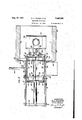
Figs. 2 and 3 are fragmentary vertical sectional views taken substantially along the line 22 of Fig. 1 in the direction of the arrows and showing the dies of the die casting machine in their closed and open positions, respectively, and also showing the unloading apparatus in its unoperated'and partially operated positions;
Fig. 4 is a fragmentary detail View also taken along the line 2-2 of Fig. 1 and showing the stripping mechanism in its completely operated position;
Fig. 5 is a plan sectional View taken substanable manner.
Positioned in direct vertical alignment beneath the upper die 25 is a lower die 25 having an entrance gate 21 aligned with a nozzle 28, which is,
in turn, aligned with the upper end of an injector gooseneck 29. The nozzle 28 and lower die 26 are supported by a cross member or p1aten 30, which is carried by the side walls I l and I2. The mechanism described thus far comprises a conventional, vertical type die casting machine with which the apparatus of the present invention is designed to cooperate. It will be understood that any suitable die casting machine may be equipped with the unloading device of the present invention and that details of the die casting machine of themselves are not pertinent to the present invention except insofar as they cooperate with the specific embodiment of the invention'to be described in detail hereinafter.
The front face of the side wall It is tapped to receive a pair of machine screws 40-40, which are adapted to pass through slots lk-4| formed in a framework supporting plate 42, the left end of which is "attached to a pintle rod 43 rotatably and slidably mounted in a pair of hinge members 44 and 45 suitably fixed to the wall l2.,, The lower end of the pintle rod 43 has a conical seat 46 formed in it for receiving the tapered tip of a pivot screw 41, which is threaded. into a boss 48 fixed n the base I8 and which is locked in place by a locking nut 49. From the foregoing, it will be apparent that the framework supporting plate 42 may be adjusted vertically with respect to the die casting machine and, when adjusted, may be locked in place thereon by means of the machine screws 48-48 and that the framework supporting plate 42, upon removal of the screws 48, may be swung out of position 0n the front of the die casting machine to make the dies and other parts of the die casting machine readily accessible.
Formed integrally with or suitably secured to the front face of the plate42 are a pair of side frame members 58 and whichare connected at their outer or forward ends by across brace The side frame members 58 and 5|. have rail plates 53 and 54, respectively; secured to them in which there are formed a pair of slots will be moved downwardly to the dot and dash position, as shown in Fig. 3, to strip a casting from the knockout pins 24.
The. side frame members 58 and 5|, in cooperation with the framework supporting plate 42, adjustably support a conveyor frame I 8| com- .prising a substantially U-shaped base plate I82 55 and 56 'for receiving the outer ends of. a pairv of support shafts 51 and 58. The shaft'51 has a pair of levers 59 and 68 attached to it and the shaft 58 has a pair of levers 6| and 62 attached to it. In addition to the levers BI and .62, the shaft 58 also has a lever 63. fixed to it; to which there is attached a contractile spring 64 having its opposite end attached to a cross brace 65. The crossbrace 65 serves to interconnect the forwarder leftehand end (Figs. 2, 3, and 5) of carriageside plates 66 and 61, through which the shafts 51 and 58 extend and which are interconnected attheir right ends, as shown' most clearlyin Figs. 2, 3 and5, by a back plate 98.. The back/plate 68 has attached to ita piston ,rod 69, whichis adapted to be actuated by fluid under pressure in a cylinder 18 mounted upon the cross brace 52.
Each of the levers 59, 68, 6| and 62 carries a pin '8 888, whichextends into a boss 8I-.8I mounted on a stripper carrying frame, designated generally by the numeral 82, whereby the M frame 82 is suspended on the levers 59 to 62, inclusive. .The stripper carrying frame 82 comprises-- a .bottom portion 83. and side flanges 84 and 85 and an end flange 85,.the bosses 8I being mounted on the side flanges and the bottom flange being'provided with a plurality of slots 81 adapted to receive machine screws 8888.
The slots 81 are spaced apart on the bottom.
:Inthe operationof the apparatus, the stripper '(Fig. l) having fixed to it a pair of side members I83 and I84, which are interconnected adjacent their outer ends by across brace I85. The conveyorframe I8! may be adjusted vertically with respect to the plate 42 andside frame members 58 and 5| by means of an adjustment screw I86 which engages an abutment member I88 fixed to the plate I82 near the bottom of it and which is threaded into a boss I81 on the framework supporting plate 42. The conveyor frame I8I may belocked in any ofits adjusted positions by means of a pluralit of machine screws .I 89I 89 threaded into the framework supporting plate 42 and extending through slots I I8-I I8 in the upwardly. extending portions 'of the base plate. I82. In addition to the machine screws I89 for holding the conveyor frame I8! in its adjusted position, a
plurality of bolts III fixed in the side members I83 and. I84 extend through slots II2I I2 in the side frame'members 58 and 5!.
The side members I83 and I84 have rail II 3 H and I I4 attached to them for receiving pins I I5- II5v and I I6I I6, respectively, which are mounted on angle members H1 and H8 forming part.
of a conveyor assembly, designated generally, by
the numeral H9. The angle members .I I1 and H8 are interconnected at their left ends (Figs.
2 and 3) by a cross brace I28 and at their right extends into a cylinder I21 mounted on-the cross brace I85. W'hen fluid under pressure is ad-.
mitted to one end of cylinder I21, piston rod I26 will move plate I22 to the position shown in Fig. 3 and'when fluid under pressure is admitted to the opposite end. of cylinder I21, the piston rod I26 will be retracted to move the plate I22 back to the position shown in Fig. '2. Y Z r e Mounted upon the side'member I84 is a cylin- I der I35, in which there is positioned a piston I36 for actuating a piston'rod I31 carrying at its right end (Fig. 1) an ejector'plate I38,'which,
at the proper time in the cycle'of operation of the apparatus, is advanced by the'piston rod to push a casting ofi of the casting receiving plate carrying frame 82will move to the right to the 7 position shown in Fig; 3 and at that position the pins 98 and 9I will reach the end of horizontally disposed slots92 and '93. As the piston rod .69' continues to ,move to the right (Fig. 3), the pins. -98-and 9| will reach the end of the horizontal slots 92 and 93 and will move into the vertically 3 disposed slots 94-44 and the strippercarrying I22 onto a chute J39 suitably mounted on the side member I83 in position to receive the castingand direct it to conveyor mechanism.(not shown);
The flow of fluid pressure to the various cylinders in the apparatus is controlled and synchro-.
Mounted directly above the cross plate i v tion with ports in a solenoid operated valv I4 I,
which may be operated by either of two solenoid coils I42 or I 43. Energization of the coil I42 will shift valve I4I to a position where fluid will b fed to upper end of cylinder I3, through the pipe I39, and the valve will remain in position to continue to supply fluid to the upper end of the cylinder I3 until the coil I43 is energized to shift the valve I l-I. Each of the valves provided in the apparatus for controlling the flow of fluid to the cylinders I3, 19, I21 and I36 is of the type which, when shifted from one operated position to the other, will remain in that position until the opposite solenoid coil associated therewith is energized.
In the operation of the apparatus, a circuit may be completed to energize the coil I42 to cause the piston I4 to move downwardly over a circuit from a current .sourc I44 upon closure of a manually operable switch I45 through series connected switches I49, I41 and I48, which operate under control of the piston rods 69, I 26 and I31 when the piston rods are in their normal retracted position, as shown in Fig. 6. The switches I46, I41 and I48 are positioned to be closed by abutments on the apparatus adapted to be actuated by the respective piston rods and when all of the piston rods are in their retracted positions, these switches will be closed. Thus if all of the unloading apparatus is in its normal inoperative position, closure of the manually operative switch I45 will complete a circuit to energize solenoid coil I42, thereby to actuate the valve MI and direct fluid under pressure to the upper end of the cylinder I3. The die actuating block I6 has a switch operating member I49 mounted thereon which is ineffective to close its associated switch I59 on downward movement of the piston I4, but which is effective to close its switch I59 momentarily just before the piston I4 reaches the upper end of its travel in moving upwardly.
From the foregoing, it is believed apparent that the switch operating member I49 will not be operative on the downward movement of the piston I4 and parts carried thereby, but, upon the upward movement of the piston I4, will close the switch I59. After a part has been die cast in the die casting machine, a switch II may be closed manually or by any suitable control mechanism (not shown) to reverse the valve I M and direct fluid under pressure to the lower end of the cylinder I3, thus to retract the die actuating block I8 to its inoperative position, as shown in Fig. 3. Just prior to the time that the die actuating block I 6 reaches its uppermost position, it will momentarily close the switch I59 to supply current from the source I 44 for energizing a valve actuating coil I52 to shift a valve I53 to position to supply fluid under pressure to the left end of the cylinder I21. When fluid is supplied to the left end of the cylinder I21, the conveyor assembly I I 9 will be moved to the right into position to receive a casting formed in the die casting machine on the plate I22 upon ejection of the casting from the upper di 25, either by the knockout pins 24 or by the stripper fingers 89. If a part or casting is ejected from the upper die 25 onto the plate I22, the plate will pivot about its hinge I23 and will effect the closure of a switch I54. The'position of the switch I59, with respect to its operating member I49, is so arranged that the plate I22 will be directly under a casting held loy the upperdi 'member 25 before the knockout pins 24 are effective'to strip casting from the die member 25 and as soon as the plate I22 is directly under the die member 25, an abutm'ent carried by the conveyor assembly I I9 will close a switch I55, which will complete'a circuit to a coil I56 associated with a reversible valve I51. The valve, upon energization of the coil I 55, will be shifted to position to direct fluid under pressure to the left end of the cylinder 19, thus to move the stripper fingers 89 over to position to engage a casting and then downwardly to strip the casting from the knockout pins 24, if the casting has adhered to the knockout pins. If, in the operation of the apparatus, the knockout pins strip the casting from the die member 25 before the stripper fingers reach their farthest actuated position, the switch I54, being closed due to the presence of a casting on the plate I22, will supply energizing current from the source I44 to coils I58 and I59 associated with the solenoid actuated valves I53 and I51 to direct fluid under pressure to the right ends of the cylinders 19 and I21, thus to return the pistons 69 and I26 to their normal inoperative position. In the event that the casting adheres to the knockout pins 24, the stripper finger will strip the casting from the knockout pins onto the plate I22 which will then close switch I54 to ffect the retraction of the stripper fingers and conveyor assembly to their inoperative position.
Mounted on the conveyor assembly H9 is a switch actuating member I69, which is operative to operate a switch I6 I. when the conveyor assembly II9 approaches the end of its travel to the left, but which is ineffective to operate the switch I 6I during movement of the conveyor assembly I I 9 to the right. Thus, as the conveyor assembly II9 approaches its normal inoperative position, it will close the switch I6I momentarily to supply current to a coil I62 associated with the reversible valve I63, which, upon energization of the coil I62, will supply fluid to the cylinder I36 to cause the piston I31 to move outwardly and carry the ejector plate I38 across the casting receiving plate I 22, thus to push a casting off of the plate I 22. When the ejector member I38 reaches the extreme end of its travel in pushing a casting off the plate I 22, it will close a switch I64, which will supply current to a coil I65 for reversing the valve I63, and cause the retraction of the ejector plate I38 to its normal inoperative position, as shown in the drawings. When the piston rods I31, I26 and 69 are retracted to their normal inoperative position, they will close the switches I46, I41 and I 48, whereby another cycle of the casting machine may be initiated.
What is claimed is:
1. An unloading apparatus for a die casting machine comprising a casting conveyor movable into the casting machine to receive a casting therefrom, a stripper operable to strip a casting from said machine onto the conveyor, means responsive to the conveyor for initiating a stripping operation of the stripper, and means responsive to a part on the conveyor for initiating a retraction of the stripper.
2. An unloading apparatus for a die casting machine comprising a casting conveyor movable into the casting machine to receive a casting therefrom, a stripper operable to strip a casting from said machine onto the conveyor, means responsive to the conveyor for initiating a stripping operation of the stripper, and means responsive to a part on a conveyor for initiating a retraction in another plane to strip a part from the machine 1 onto the conveyor, and actuating means for said ejecting means.
, GEORGE L. CHERRY.
CHARLES C. VEALE.
REFERENCES CITED I The following references are of record in the Number file of this patent:
Q UNITED STATES PATENTS Date Name Kenworthy Jan. 18, 1916 Blount Aug. 10, 19 26 Sma11ey .July 19, 1932 Tucker Aug. 1'7, 1943
Priority Applications (1)
| Application Number | Priority Date | Filing Date | Title |
|---|---|---|---|
| US558008A US2425362A (en) | 1944-10-10 | 1944-10-10 | Unloading apparatus |
Applications Claiming Priority (1)
| Application Number | Priority Date | Filing Date | Title |
|---|---|---|---|
| US558008A US2425362A (en) | 1944-10-10 | 1944-10-10 | Unloading apparatus |
Publications (1)
| Publication Number | Publication Date |
|---|---|
| US2425362A true US2425362A (en) | 1947-08-12 |
Family
ID=24227780
Family Applications (1)
| Application Number | Title | Priority Date | Filing Date |
|---|---|---|---|
| US558008A Expired - Lifetime US2425362A (en) | 1944-10-10 | 1944-10-10 | Unloading apparatus |
Country Status (1)
| Country | Link |
|---|---|
| US (1) | US2425362A (en) |
Cited By (12)
| Publication number | Priority date | Publication date | Assignee | Title |
|---|---|---|---|---|
| US2669759A (en) * | 1951-06-20 | 1954-02-23 | Emery I Valyi | Mold ejecting mechanism for mold-forming machines |
| US2696646A (en) * | 1951-05-29 | 1954-12-14 | Loma Machine Mfg Co Inc | Method and apparatus for semicontinuous casting |
| US2724878A (en) * | 1952-06-13 | 1955-11-29 | Emery I Valyi | Mold-forming machine |
| US2733490A (en) * | 1956-02-07 | X x x x x x x | ||
| US2787815A (en) * | 1955-03-25 | 1957-04-09 | Nat Lead Co | Journal bearing casting apparatus |
| US2795021A (en) * | 1955-02-11 | 1957-06-11 | Gen Electric | Horizontal die casting machine |
| US2856079A (en) * | 1958-10-14 | Article handler | ||
| US2863188A (en) * | 1953-11-23 | 1958-12-09 | Harrison George | Method and means for casting slugs |
| US2946102A (en) * | 1960-07-26 | mills | ||
| US3049767A (en) * | 1958-12-03 | 1962-08-21 | Aluminum Co Of America | Casting equipment |
| US4719059A (en) * | 1985-12-23 | 1988-01-12 | Duraco Products, Inc. | Process of handling and transferring a molded product |
| US4808102A (en) * | 1985-12-23 | 1989-02-28 | Duraco Products, Inc. | Apparatus for handling and transferring a molded article |
Citations (4)
| Publication number | Priority date | Publication date | Assignee | Title |
|---|---|---|---|---|
| US1168313A (en) * | 1916-01-18 | Charles F Kenworthy | Furnace. | |
| US1595139A (en) * | 1924-12-09 | 1926-08-10 | Western Electric Co | Annealing apparatus |
| US1867772A (en) * | 1929-06-05 | 1932-07-19 | Hevi Duty Electric Co | Recuperative counterflow furnace |
| US2327227A (en) * | 1941-02-06 | 1943-08-17 | Hydraulic Dev Corp Inc | Injection molding machine |
-
1944
- 1944-10-10 US US558008A patent/US2425362A/en not_active Expired - Lifetime
Patent Citations (4)
| Publication number | Priority date | Publication date | Assignee | Title |
|---|---|---|---|---|
| US1168313A (en) * | 1916-01-18 | Charles F Kenworthy | Furnace. | |
| US1595139A (en) * | 1924-12-09 | 1926-08-10 | Western Electric Co | Annealing apparatus |
| US1867772A (en) * | 1929-06-05 | 1932-07-19 | Hevi Duty Electric Co | Recuperative counterflow furnace |
| US2327227A (en) * | 1941-02-06 | 1943-08-17 | Hydraulic Dev Corp Inc | Injection molding machine |
Cited By (12)
| Publication number | Priority date | Publication date | Assignee | Title |
|---|---|---|---|---|
| US2733490A (en) * | 1956-02-07 | X x x x x x x | ||
| US2856079A (en) * | 1958-10-14 | Article handler | ||
| US2946102A (en) * | 1960-07-26 | mills | ||
| US2696646A (en) * | 1951-05-29 | 1954-12-14 | Loma Machine Mfg Co Inc | Method and apparatus for semicontinuous casting |
| US2669759A (en) * | 1951-06-20 | 1954-02-23 | Emery I Valyi | Mold ejecting mechanism for mold-forming machines |
| US2724878A (en) * | 1952-06-13 | 1955-11-29 | Emery I Valyi | Mold-forming machine |
| US2863188A (en) * | 1953-11-23 | 1958-12-09 | Harrison George | Method and means for casting slugs |
| US2795021A (en) * | 1955-02-11 | 1957-06-11 | Gen Electric | Horizontal die casting machine |
| US2787815A (en) * | 1955-03-25 | 1957-04-09 | Nat Lead Co | Journal bearing casting apparatus |
| US3049767A (en) * | 1958-12-03 | 1962-08-21 | Aluminum Co Of America | Casting equipment |
| US4719059A (en) * | 1985-12-23 | 1988-01-12 | Duraco Products, Inc. | Process of handling and transferring a molded product |
| US4808102A (en) * | 1985-12-23 | 1989-02-28 | Duraco Products, Inc. | Apparatus for handling and transferring a molded article |
Similar Documents
| Publication | Publication Date | Title |
|---|---|---|
| US2425362A (en) | Unloading apparatus | |
| US2759221A (en) | Injection (plastic) moulding machines | |
| GB1101694A (en) | Die-casting apparatus | |
| US2298044A (en) | Molding machine | |
| GB1180370A (en) | Die-Casting Machines | |
| GB1444186A (en) | Apparatus for forming and trimming hollow articles | |
| GB1325215A (en) | Mould breaking device | |
| US1981381A (en) | Means for assuring the safe working of automatic pressure die-casting apparatus | |
| US2289102A (en) | Automatic molding machine | |
| US2717433A (en) | Metal casting machine | |
| US3340850A (en) | Apparatus for continuously conveying tubes through a hot galvanising bath | |
| GB950008A (en) | Overhead squeeze moulding machine | |
| US2220776A (en) | Pressure casting apparatus | |
| US2946102A (en) | mills | |
| US2782471A (en) | Molding machines | |
| US2485284A (en) | Stripper | |
| US3242532A (en) | Mold loading apparatus | |
| US2410324A (en) | Machine for molding thermosetting materials | |
| US2874853A (en) | Quenching press with work handling mechanism | |
| US1917004A (en) | Conveyer system | |
| US1322502A (en) | X d die casting machine | |
| US2678656A (en) | Automatic quenching device | |
| US3044119A (en) | Automatic injection molding machines | |
| US2790995A (en) | Hydraulic press | |
| US3010173A (en) | Multiple station block machine |