US2425015A - Grid winding machine - Google Patents
Grid winding machine Download PDFInfo
- Publication number
- US2425015A US2425015A US463569A US46356942A US2425015A US 2425015 A US2425015 A US 2425015A US 463569 A US463569 A US 463569A US 46356942 A US46356942 A US 46356942A US 2425015 A US2425015 A US 2425015A
- Authority
- US
- United States
- Prior art keywords
- grid
- machine
- mandrel
- lead screw
- gear
- Prior art date
- Legal status (The legal status is an assumption and is not a legal conclusion. Google has not performed a legal analysis and makes no representation as to the accuracy of the status listed.)
- Expired - Lifetime
Links
- 238000004804 winding Methods 0.000 title description 22
- 230000033001 locomotion Effects 0.000 description 20
- 230000007246 mechanism Effects 0.000 description 13
- 230000008859 change Effects 0.000 description 7
- 238000010276 construction Methods 0.000 description 7
- 230000008878 coupling Effects 0.000 description 4
- 238000010168 coupling process Methods 0.000 description 4
- 238000005859 coupling reaction Methods 0.000 description 4
- 230000015572 biosynthetic process Effects 0.000 description 2
- 238000005266 casting Methods 0.000 description 1
- 230000006835 compression Effects 0.000 description 1
- 238000007906 compression Methods 0.000 description 1
- 230000001419 dependent effect Effects 0.000 description 1
- 239000002184 metal Substances 0.000 description 1
- 230000004048 modification Effects 0.000 description 1
- 238000012986 modification Methods 0.000 description 1
- 238000006467 substitution reaction Methods 0.000 description 1
Images


Classifications
-
- H—ELECTRICITY
- H01—ELECTRIC ELEMENTS
- H01J—ELECTRIC DISCHARGE TUBES OR DISCHARGE LAMPS
- H01J19/00—Details of vacuum tubes of the types covered by group H01J21/00
-
- H—ELECTRICITY
- H01—ELECTRIC ELEMENTS
- H01J—ELECTRIC DISCHARGE TUBES OR DISCHARGE LAMPS
- H01J2893/00—Discharge tubes and lamps
- H01J2893/0001—Electrodes and electrode systems suitable for discharge tubes or lamps
- H01J2893/0012—Constructional arrangements
- H01J2893/0026—Machines for manufacture of grids or anodes
-
- Y—GENERAL TAGGING OF NEW TECHNOLOGICAL DEVELOPMENTS; GENERAL TAGGING OF CROSS-SECTIONAL TECHNOLOGIES SPANNING OVER SEVERAL SECTIONS OF THE IPC; TECHNICAL SUBJECTS COVERED BY FORMER USPC CROSS-REFERENCE ART COLLECTIONS [XRACs] AND DIGESTS
- Y10—TECHNICAL SUBJECTS COVERED BY FORMER USPC
- Y10T—TECHNICAL SUBJECTS COVERED BY FORMER US CLASSIFICATION
- Y10T82/00—Turning
- Y10T82/20—Lathe for screw cutting
-
- Y—GENERAL TAGGING OF NEW TECHNOLOGICAL DEVELOPMENTS; GENERAL TAGGING OF CROSS-SECTIONAL TECHNOLOGIES SPANNING OVER SEVERAL SECTIONS OF THE IPC; TECHNICAL SUBJECTS COVERED BY FORMER USPC CROSS-REFERENCE ART COLLECTIONS [XRACs] AND DIGESTS
- Y10—TECHNICAL SUBJECTS COVERED BY FORMER USPC
- Y10T—TECHNICAL SUBJECTS COVERED BY FORMER US CLASSIFICATION
- Y10T82/00—Turning
- Y10T82/25—Lathe
- Y10T82/2531—Carriage feed
- Y10T82/2549—Feedscrews and rods
Definitions
- V. H. VAN SANT GRID WINDING MACHINE 9 Sheets-Sheet 2 Filed OCT.. 27, 1942 ug. 59 3947., v M VAN SANT ZAZ GRID WINDING MACHINE Filed OC'l'.. 2?'1942 9 Sheets-Sheet 3 All@ 5, 1947' v. H. VAN SANT GRID WINDING MACHINE Filed Oct. 27, 1942 9 Sheets--Sheel 4 lNVEN ma/ZKW BY Aug. 59 3%? v. H. VAN SANT 21,425,7@5
- This invention relates to machine tools and in particular to a machine for automatically constructing grid electrodes for electronic vacuum tubes. It also relates to machines for winding coils or springs and in general to any machine to-ol which combines a rotational and a rectilinear motion as, for example, a screw cutting lathe or mill.
- gear train located between the rotating element or spindle and the element for producing rectilinear motion, the latter commonly taking the form of a lead screw and an associated traveling half nut.
- the gears of the train are interchangeable in o-rder that various ratios may be obtained between the rotation ofv the spindle with respect to the rotation of the lead screw.
- gears regardless of the numb-er of change gears which may be provided there will always be some ratios which are not obtainable since the ratios change abruptly from one value to another depending on the number ofteeth in the gears of the train, and obviously there cannot be a fractional number of teeth.
- change gears are so chosen that some particular ratio is obtained to suit the type of work to be done.
- the machine tool be a screw cutting lathe
- gears are chosen which will permit the lathe to cut screws having any number of standard threads per inch.
- Some lathes are provided with so called transposing gears.
- metric threads may be cut on a lathe having an English lead screw and English threads may be cut on a lathe having a metric lead screw. This is possible since the number of centimeters per inch is for all practical purposes the decimal 2.54, a number which may be expressed by the relative simple fraction 12F[/50.
- I provide a mechanism whereby a lead screw having English or metric threads, may be inclined at an angle with the normal direction of rectilinear motion.
- the traveling half nut traverses the lead screw unit distance, the corresponding distance in the direction of rectilinear motion is equal to this unit distance times the cosine of the angle of lead screw inclination. It is thus possible to obtain any desired relation between the rate of spindle rotation and the rate of normal rectilinear motion.
- the primary object cf my invention to provide a positive mechanism which, when applied to any machine incorporating a rotational with a rectilinear ⁇ motion, will permit the obtaining of any velocity ratio between the two motions.
- Another object of my invention is to devise a grid winding machine which may be adjusted so as to produce a wound grid having any desired pitch between the grid turns.
- Still another object of my invention is to devise a grid winding machine capable of winding a grid electrode having a variable pitch helix.
- a further object of my invention is to provide a mechanism which when applied to a screw cutting lathe will permit the cutting of screws or worms having any pitch and in accordance with any standard.
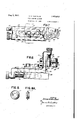
- FIG. 1 is a front elevation of a grid winding machinek showing the essential elements constituting my invention.
- Fig. 4 is an end elevational View of the mandrel headstock.
- FIGs. 5 and 6 ⁇ show a side and end elevation respectively of the mandrel o-n which the grid is formed.
- Figs. '7 and 8 show in plan and side elevation, respectively, a mechanism for notching or swaging the grid support bars on which the helix is wound.
- FIGs. 9 and 9A are respectively side and end elevational views of the hardened roll-er for forming notches in a grid support.
- Figs. 10 and 11 show in side and plan elevation respectively, the reel mechanismwhich holds and feeds the helix wire to the grid mandrel.
- Figs. 12 and 13 are sectional and end elevational views of the mandrel tailstock respectively.
- Fig. 14 is a sectional view of gearing for driving the inclined lead screw.
- Fig. l5 shows an arrangement for setting and clamping the inclined lead screw.
- Figs. 16 and 17 show two sectional views or a half nut and locking arrangement connected with the carriage of the machine.
- Fig. 18 shows a contact making arrangement for automatically starting and stopping the rotation of the grid mandrels.
- Fig. 19 shows how one of the machine elements could be formed so as to wind a grid having a variable pitch.
- Fig. 20 is a perspective view of a grid of the type made on the machine illustrated.
- the particular kind of grid electrode which the machine of my invention is designed to fabricate is known as a wound grid in which the helix wire is swaged into notches that have been formed in the grid support bars.
- This type of construction is usually employed for grid electrodes associated with high power tubes. With smaller grids the helix wire is in general welded to the grid support wires.
- the bed of the grid winding machine is represented by the numeral I.
- the headstock 2 which carries the spindle 3 and four step cone pulley assembly 4.
- the cone pulley together with the back gearing (enclosed in housing provides for eight spindle speeds.
- a detailed showing and description of the headstock assembly is not included in this specification since the construction is well known and forms no part of the present invention.
- a clutch plate 6 Fastened to the spindle 3 is a clutch plate 6, the latter forming part of a pin clutch mechanism 1 which serves to engageY and disengage a driving bar 8 at predetermined periods during the operation of the machine.
- the pin clutch is operated by solenoid 9 with spring return I0.
- the pin clutch is not described in detail since it forms no part of my invention. The manner in which it functions in connection with other elements of the machine will be described later in the specification.
- the driving bar 8 is journaled between bearings in the mandrel head stock I I and the tail bracket I2.
- the detailed i'construction of the mandrel head stock I I is shown in Figs. 3, and 4, Fig 3 being a View taken through the vertical section 3-3 of Fig. 4.
- YI3 represents the mandrel headstock housing which is bolted to the.
- a mandrel holder 23 is keyed and rigidly locked within the spindle I1.
- the key is shown at 29 and the locking nut at 30, the latter together with the flange 3
- the mandrel holder has eight lengthwise grooves 32-39, cut to a depth such that they extend below the surface of the mandrel which is fastened to the end of the holder. Within these grooves are placed the grid support bars around which the helix is to be wound.
- Keyway 49 is also cut across the face of the mandrel holder. This keyway acts as a guide to line up .the mandrel and mandrel holder to prevent relative rotation.
- Pins 4I pressed into the mandrel holder and extending Within the mandrel when it is in position serve to prevent lateral motion of the mandrel.
- the mandrel is held to the mandrel holder by a bolt which extends completely through the center of the holder and screws into the mandrel.
- Figs. 5 and 6 consists of a flange 43 having an integral key 44 extending from one face and a grid forming surface 4-5 extending from the other face.
- the key 44 mates with the keyway 4B as described above.
- the grid forming surface 45 has a contour corresponding to the inside dimensions of the grid electrode which is to be constructed.
- the surface may be round or fiat or any other desired shape.
- Figs. 5 and 6 show a ilat surface for forming a flat grid electrode. Both ends of the surface have grooves 46 extending along their entire length and continue as holes 41 through the flange 43 where they register with an oppositely disposed pair of grooves, for example 34 and 38, in the mandrel holder 28.
- the grid support bars extend through the holes 41 and lay in the grooves 46 where they are notched and swaged as will hereinafter be described. As the machine operates these bars are pulled through the holes and along the grooves, and in order exert a small amount of friction against their motion a unit consisting of a button 43, a spring 49, and an adjusting screw 50 is assembled within the ange 43. The pressure of the button 48 against the grid support bar supplies the required friction.
- the flange 26 integral with the mandrel headstock, supports a plurality of units 21 for notching and swaging the grid support bars, and for holding the reel containing the helixwire. Only one unit is shown so as not to unnecessarily complicate the figure.
- a unit contain- 'ing a rotating metal saw may be substituted for a slot 5'3 in the bracket.
- Element 5.8 is a double washer.
- a groove ⁇ 54 in the flange mates witha guide 55 on the bracket for giving alignment and rigidity to the construction.
- the desired radial position of the bracket with respect to the flange 26 is obtained by means of the screw 56. Any back-'lash or lost motion in screw 5B is taken up by the ⁇ locking screw 51 which bears, against the periphery of the flange 26.
- a portion 5.9 of the bracket 5I extends normal to the face of the ange 26, and mounts an adjustable holder 68 for the notching or swaging roller 6I.
- the gure illustrates. a swaging roller.
- a notching roller is illustrated in Figs. 9 and 9Athis roller having an annular sharpened edge flange BI as shown.
- Screw 62 adjusts the roller SI to thedesired distance from th'e face of theflange 26, or more accurately, to the desired point in relation to the edge of the grid forming surface 45 of the ⁇ mandrelv shown in Fig. 5.
- Screws 63 clamp the holder rigidly in place after the adjustment has been made.
- the roller 6I isjournaled onpin 6.1i, the latter being clamped. between the two arms 65 and 6,6 of the holder 60 by the screws 6I..
- Figs. 10 and l1 show a side and end elevation .3 of the reel containing the helix wire togeth'er with tensioning means for keeping the wire taut as it unreels and is fastened to the grid support bars during the operation of the machine.
- 8 is Z-shaped and is fastened to the flange 26 by screws
- 25 is xed in position adjacent the mandrel while pulley
- 24 is adjustable in order that it may be made to line up with the notching and swaging units.
- Fig. 12 is a view taken thru the vertical section
- 23 form the main housing and cover plate respectively for th'e tailstock mechanism.
- the tailstock unit is mounted on the carriage 95 and moves transversely with the latter during the operation of the machine.
- the housing encloses a train of gears extending from gear
- the gear trains in the headstock and tailstock are so chosen that the headstock spindle and the tailstock spindle have the same angular motion.
- 29 is splined to the driving shaft 8 by the spline
- 32 is journaled in bearings
- 31 is keyed to a shaft extension of the spindle. This hand wheel permits the hand operation of the entire machine while setting up the work prior t automatic operation.
- the tail mandrel illustrated in Fig. 12 is designed to cooperate with a headstock mandrel for winding a flat grid electrode.
- Th'e tail mandrel is divided into two parts, th'e main part being integral with the tapered shank and the other part or segment IM being fastened to the main part by screws
- the tail mandrel pulls the grid support bars thru the head stock mandrel at such a rate that for one revolution of the mandrels the advance equals the desired pitch of the grid helix wires.
- gear B8 mounted on the end of spindle 3 drives the screw gear
- the gears 69 and 13 are change gears and are so chosen that th'e screw gear
- the change gearing is known as simple gearing as is well known in the machine tool art.
- Reverse lever 14 is pivoted about the axis of gear l2 and when thrown to the upper position causes the disengagement of gears 68 and 'iii and brings into mesh the gears 68 and 1
- the back gearing is shown at 5' but will not be described in detail since its construction is well known in the art.
- the screw gear 69 is keyed to the shaft l5, the latter being journaled between bearings in block 'I6 and the feed gear bearing block 'il which are fastened to the bed of the machine.
- Fig. 14 is a view taken through the section
- the gure shows a preferred arrangement of parts which permits the rotary motion of shaft 'i5 to be transferred to the lead screw
- Fig. l shows the maximum value of this angle to be 30 but this value is illustrative only and is in no way to be considered as limiting.
- the bearing block 'l1 comprises two bearings 19 and 79 at right angles to each other.
- the bearing I9 journals one end of shaft l5 as mentioned above and the other bearing 79' journals shaft 85.
- also journals shaft Sil.
- ) is also journaled in yoke member S2 while the latter serves to journal one end of the lead screw 18.
- Mounted in operative relationship on shaft l5, shaft 80, and lead screw i8 are three spiral miter gears 83, 81
- Suitable thrust bearings 36 and collars 8l are mounted on the various shafts to constrain the gears to positions for quiet and efficient operation.
- Fig. 15 is a sectional plan View of the far end of the lead screw together with a clamping device which is constrained to move in an arcuate slot B8 in member 89. Referring to Figs. 1 and 15,
- the bearing 9G journals the shaft extension 9
- the bearing may be sen curely clamped by screws 92 ⁇ and 93 at any position on the member 89 'depending on the angle which the lead screw makes with the horizontal.
- is some-what greater than the length of the half nut li, Fig. 17. This prevents the mechanism of Fig. 17 from jamming against the clamping arrangement of Fig. 15 since the half nut disengages the lead screw.
- Fig. 16 is a view through section Iii-l of Fig. 1
- Fig. 17 is a View through section I-il of the same gure. Both Figs. 16 and 17 Vassume the lead screw to be in a horizontal rather than in an inclined position.
- 05 when fastened together on opposite sides of the member N2 constitute a retaining unit for other parts of the mechanism.
- i and the cam follower 2 are assembled iwith the part
- the cam Hd which is operated by the handle
- 08 slides over the leadscrew and functions as a guide to always maintain the half-nut in a position to easily Yengage the lead-screw regardless of the angle which the latter may take.
- Fig. 18 shows a mechanism for automatically stopping vthe rotation of the grid mandrels while the 'traverse motion of the carriage and tailstock continues.
- a device of this kind is desirable when a number of short grid electrodes are to be made for one complete traverse motion of the carriage, since it is undesirable to continue mounting the helixwire on the grid support bars between the individual grids.
- the individual grids may be suitably separated after a plurality have been wound.
- 50 is fastened to the back of the carriage 95. Within the groove
- 53 is Ymounted on the l bed of the machine in operative relationship shaft 8 and consequently all rotary motion within the head and tailstocks.
- a suitable mandrel corresponding to the type of grid which is to be wound such as, for example, that shown in Fig. 5, is fastened in place on the mandrel holder shown in Fig. 3.
- Two grid support wires are threaded through slots 34 and 38 of the mandrel holder, see Fig.- 4, and extended through the holes 01 and the grooves 46 of the mandrel and then caught between the jaws of the tailstock mandrel
- 38 may be almost in contact with the headstock mandrel.
- FIG. 9 is placed in the upper left hand slot 54 of the head stock, see Fig. 4.
- a swaging device see Figs. l and 8, is positioned as shown in Fig. 4 and another similar swaging device is positioned in the lower left hand groove 54, also shown onA Fig. 4.
- the helix wire is wound on a reel, see Fig. 10, and positioned in the upper right hand groove 54' showv in Fig. 4.
- the :proper change gearsV are selected for the ⁇ change gears combination, see'Fig. 2, such as, for example, those given in the above illustration whereinr a grid of 91/4 turns per inch is to be made.
- the lead' screw is set at an angle of 13 21" .and securely clamped in position.
- the cam 52 shown on the extreme left in Fig. 18V is positioned so that its leading edge will operate theV contact mechanism
- a second cam is then positionedso that its leading edge is spaced a' distance from the following edge of the rst 9 cam equal to the length of helix wire to be wound on the second grid.
- a third cam is positioned so that its leading edge is similarly spaced from the following edge of the second cam, etc.
- the machine is then operated by the hand wheel on the tailstock until thev iirst turn or so of the helix wire is securely fastened to the grid support bars.
- the machine is then started and from then on the grids are automatically wound.
- a curved slot for the straight slot ID3 in member 102 of Fig. 1.
- the curved slot could be constructed so that a grid having a variable pitch winding would be formed, grids of this type being employed in so-called variable mu tubes of the remote cut-oi type.
- a slot for this type of grid would take the approximate form shown at
- the slot in Fig. 19 would permit only one grid at a time being formed but it would be merely a matter of design to form a slot capable of forming a plurality of grids.
- a headstock and tailstock having a work-piece mounted thereon, means for -producing relative rectilinear travel between said headstock and tailstock to vary the distance therebetween as a fabricating operation is performed on said work-piece, said means including an actuating element disposed at an angle to the line of said relative rectilinear travel, and means for varying said angle to produce corresponding variation in the rate of said relative rectilinear travel.
- actuating element is la lead screw having motion translating connection with said tailstock, said machine further including means for rotating said lead screw.
- actuating element is a lead screw having motion translating connection with said tailstock, said machine further including means for rotating said lead screw, the said rotating means also being operable to rotate said work-piece.
- angle varying means includes a member operable to set said actuating element in any one of an infinite number of diierent angular relationships to said line of travel, within a predetermined maximum angle.
- actuating element is a lead screw
- machine further includes means for rotating said screw, and a slotted element co-operating with said screw to convert the rotation of said screw into rectilinear travel of said tailstock at a rate dependent upon the setting of said angle varyi-ng means.
- a machine as defined in claim l wherein the work-piece is a wire,1and the machine further includes a plurality of support bars co-operating with said head and tailstocks to form said wire into a predetermined shape, and means for stopping the operation when formation ofthe wire to said shape has been completed.
- means including a rotatable coupling for causing said head and tailstocks to operate upon said workpiece, and means in the path of said relative rectilinear travel to cause release of said coupling when the operation on the work-piece is completed.
- 'means including a rotatable coupling for causing said head and tailstocks to operate upon said workpiece, and electrical means in the path of said relative rectilinear travel to cause release of said coupling when the operation on the work-piece is completed.
Landscapes
- Transmission Devices (AREA)
Description
v. H. VAN lSANT v 2,425,015
GRID WINDING MACHINE Aug. 5, 1947.v
Filled oct. 27, 1942 9 Sheets-Sheet 1 INVENToR. l//craR HKM/SAN? Aug.'5,1947.
V. H. VAN SANT) GRID WINDING MACHINE 9 Sheets-Sheet 2 Filed OCT.. 27, 1942 ug. 59 3947., v M VAN SANT ZAZ GRID WINDING MACHINE Filed OC'l'.. 2?'1942 9 Sheets-Sheet 3 All@ 5, 1947' v. H. VAN SANT GRID WINDING MACHINE Filed Oct. 27, 1942 9 Sheets--Sheel 4 lNVEN ma/ZKW BY Aug. 59 3%? v. H. VAN SANT 21,425,7@5
GRID WINDING MACHINE Filed Oct. 27, 1942 9 Sheets-Shea?l 5 Aug. 5,1%?. v. H. VAN SANT GRID WINDING MACHINE Filed Oct. 27, 1942 9 Sheets-Sheet 6 av u Aug. 5, 194?. v. H. VAN SANT GRID -wINDING' MACHINE Filed OCT.. 27, 1942 9 Sheets-S1166?.
mmw Y QNN NNN
NNN
INVEToR. #cme A. Zw Jf/W' Aug. 5, 1947. v. H. VAN. SANT 2,425,015
GRID WINDING MACHINE Filed Oct. 27, 1942 9 Sheets-Sheet 8 Aug. 5, 194'?i v. A. VAN SANT .2,425,015
GRID WINDING MACHINE Filed oct. 27, 1942 9 sheets-sheet 9 Patented Aug. 5, i947 GRID WINDING MACHEN@ Victor H. Van Sant, Westiield, N. J., assigner to Federal Telephone & Radio Corporation, New York, N. Y., a corporation of Delaware Application October 27, 1942, Serial No. 463,569
l2 Claims. l
This invention relates to machine tools and in particular to a machine for automatically constructing grid electrodes for electronic vacuum tubes. It also relates to machines for winding coils or springs and in general to any machine to-ol which combines a rotational and a rectilinear motion as, for example, a screw cutting lathe or mill.
In machines or machine tools of these types there is usually a gear train located between the rotating element or spindle and the element for producing rectilinear motion, the latter commonly taking the form of a lead screw and an associated traveling half nut. The gears of the train are interchangeable in o-rder that various ratios may be obtained between the rotation ofv the spindle with respect to the rotation of the lead screw. However, regardless of the numb-er of change gears which may be provided there will always be some ratios which are not obtainable since the ratios change abruptly from one value to another depending on the number ofteeth in the gears of the train, and obviously there cannot be a fractional number of teeth. In actual practice, change gears are so chosen that some particular ratio is obtained to suit the type of work to be done. For example, if the machine tool be a screw cutting lathe, gears are chosen which will permit the lathe to cut screws having any number of standard threads per inch. Some lathes are provided with so called transposing gears. When these gears are included in the gear train, metric threads may be cut on a lathe having an English lead screw and English threads may be cut on a lathe having a metric lead screw. This is possible since the number of centimeters per inch is for all practical purposes the decimal 2.54, a number which may be expressed by the relative simple fraction 12F[/50.
However, occasions frequently arise wherein it would be desirable to obtain a relation between spindle rotation and'lead screw advance other than would normally be available. One such example would be in the cutting of diametral pitch worm gears. The number of threads per unit length of these gears involves the factor rr the ratio between the circumference and the diameter of a circle, and this factor is incommensurable with any whole or fractional number of turns per inch or per centimeter such as might appear on standard lead screws.
In accordance with my invention I provide a mechanism whereby a lead screw having English or metric threads, may be inclined at an angle with the normal direction of rectilinear motion. When the traveling half nut traverses the lead screw unit distance, the corresponding distance in the direction of rectilinear motion is equal to this unit distance times the cosine of the angle of lead screw inclination. It is thus possible to obtain any desired relation between the rate of spindle rotation and the rate of normal rectilinear motion.
It is therefore, the primary object cf my invention to provide a positive mechanism which, when applied to any machine incorporating a rotational with a rectilinear` motion, will permit the obtaining of any velocity ratio between the two motions.
Another object of my invention is to devise a grid winding machine which may be adjusted so as to produce a wound grid having any desired pitch between the grid turns.
Still another object of my invention is to devise a grid winding machine capable of winding a grid electrode having a variable pitch helix.
A further object of my invention is to provide a mechanism which when applied to a screw cutting lathe will permit the cutting of screws or worms having any pitch and in accordance with any standard.
Other objects andrapplications of my invention willV be appreciated from a consideration oi the following, detailed description taken in conjunction with the accompanying drawings in which Fig. 1 is a front elevation of a grid winding machinek showing the essential elements constituting my invention.
my machine known as the mandrel headstecl; on
` line 3--3 of Fig. 4.
Fig. 4 is an end elevational View of the mandrel headstock. f
IFigs. 5 and 6`show a side and end elevation respectively of the mandrel o-n which the grid is formed.
Figs. '7 and 8 show in plan and side elevation, respectively, a mechanism for notching or swaging the grid support bars on which the helix is wound.
I`Figs. 9 and 9A are respectively side and end elevational views of the hardened roll-er for forming notches in a grid support.
Figs. 10 and 11 show in side and plan elevation respectively, the reel mechanismwhich holds and feeds the helix wire to the grid mandrel.
Figs. 12 and 13 are sectional and end elevational views of the mandrel tailstock respectively.
Fig. 14 is a sectional view of gearing for driving the inclined lead screw.
Fig. l5 shows an arrangement for setting and clamping the inclined lead screw.
Figs. 16 and 17 show two sectional views or a half nut and locking arrangement connected with the carriage of the machine.
Fig. 18 shows a contact making arrangement for automatically starting and stopping the rotation of the grid mandrels.
Fig. 19 shows how one of the machine elements could be formed so as to wind a grid having a variable pitch.
Fig. 20 is a perspective view of a grid of the type made on the machine illustrated,
The particular kind of grid electrode which the machine of my invention is designed to fabricate is known as a wound grid in which the helix wire is swaged into notches that have been formed in the grid support bars. This type of construction is usually employed for grid electrodes associated with high power tubes. With smaller grids the helix wire is in general welded to the grid support wires.
Referring to Fig. 1, the bed of the grid winding machine is represented by the numeral I. Mounted on one end of the bed is the headstock 2 which carries the spindle 3 and four step cone pulley assembly 4. The cone pulley together with the back gearing (enclosed in housing provides for eight spindle speeds. A detailed showing and description of the headstock assembly is not included in this specification since the construction is well known and forms no part of the present invention.
Fastened to the spindle 3 is a clutch plate 6, the latter forming part of a pin clutch mechanism 1 which serves to engageY and disengage a driving bar 8 at predetermined periods during the operation of the machine. The pin clutch is operated by solenoid 9 with spring return I0. The pin clutch is not described in detail since it forms no part of my invention. The manner in which it functions in connection with other elements of the machine will be described later in the specification.
The driving bar 8 is journaled between bearings in the mandrel head stock I I and the tail bracket I2. The detailed i'construction of the mandrel head stock I I is shown in Figs. 3, and 4, Fig 3 being a View taken through the vertical section 3-3 of Fig. 4. In these gures YI3 represents the mandrel headstock housing which is bolted to the.
bed of the machine. It consists of a suitable casting for enclosing a chain of gears extending from gear i4, which is keyed to the driving bar 8, through idler gear I5 to gear IS, the latter being integral with a spindle I1. Gears I4 and I5 have the same number of teeth and rotate in the same direction at unity ratio. Spindle I 1 is journaled in bearings I8 and I9 while thrust is taken by the ball bearing 20. The driving bar 8 which as above mentioned is keyed to gear I4 is constrained against traverse motion by thrust washers and collars, the latter being pinned to the bar. In Figs. 1 and 3 the thrust washers are parts 2I and 22 and the collars are 23` and the pin clutch mechanism 1. The cover plate 24 for the mandrel headstock housing is fastened to the housing by ten screws indicated by the dotted circles 25 in Fig. 4.
A mandrel holder 23 is keyed and rigidly locked within the spindle I1. The key is shown at 29 and the locking nut at 30, the latter together with the flange 3| on the opposite end of the mandrel bearing against the ends of the spindle I1. The mandrel holder has eight lengthwise grooves 32-39, cut to a depth such that they extend below the surface of the mandrel which is fastened to the end of the holder. Within these grooves are placed the grid support bars around which the helix is to be wound. Keyway 49 is also cut across the face of the mandrel holder. This keyway acts as a guide to line up .the mandrel and mandrel holder to prevent relative rotation. Pins 4I, pressed into the mandrel holder and extending Within the mandrel when it is in position serve to prevent lateral motion of the mandrel. The mandrel is held to the mandrel holder by a bolt which extends completely through the center of the holder and screws into the mandrel.
.'Ihe mandrel itself, shown in Figs. 5 and 6, consists of a flange 43 having an integral key 44 extending from one face and a grid forming surface 4-5 extending from the other face. The key 44 mates with the keyway 4B as described above. The grid forming surface 45 has a contour corresponding to the inside dimensions of the grid electrode which is to be constructed. The surface may be round or fiat or any other desired shape. Figs. 5 and 6 show a ilat surface for forming a flat grid electrode. Both ends of the surface have grooves 46 extending along their entire length and continue as holes 41 through the flange 43 where they register with an oppositely disposed pair of grooves, for example 34 and 38, in the mandrel holder 28. The grid support bars extend through the holes 41 and lay in the grooves 46 where they are notched and swaged as will hereinafter be described. As the machine operates these bars are pulled through the holes and along the grooves, and in order exert a small amount of friction against their motion a unit consisting of a button 43, a spring 49, and an adjusting screw 50 is assembled within the ange 43. The pressure of the button 48 against the grid support bar supplies the required friction.
Returning now to Fig. 4, the flange 26, integral with the mandrel headstock, supports a plurality of units 21 for notching and swaging the grid support bars, and for holding the reel containing the helixwire. Only one unit is shown so as not to unnecessarily complicate the figure. In the construction of the larger grids which usually require extra large supporting bars, a unit contain- 'ing a rotating metal saw may be substituted for a slot 5'3 in the bracket. Element 5.8 is a double washer. A groove` 54 in the flange mates witha guide 55 on the bracket for giving alignment and rigidity to the construction. The desired radial position of the bracket with respect to the flange 26 is obtained by means of the screw 56. Any back-'lash or lost motion in screw 5B is taken up by the `locking screw 51 which bears, against the periphery of the flange 26.
A portion 5.9 of the bracket 5I extends normal to the face of the ange 26, and mounts an adjustable holder 68 for the notching or swaging roller 6I. The gure illustrates. a swaging roller. A notching roller is illustrated in Figs. 9 and 9Athis roller having an annular sharpened edge flange BI as shown. Screw 62 adjusts the roller SI to thedesired distance from th'e face of theflange 26, or more accurately, to the desired point in relation to the edge of the grid forming surface 45 of the` mandrelv shown in Fig. 5. Screws 63 clamp the holder rigidly in place after the adjustment has been made. The roller 6I isjournaled onpin 6.1i, the latter being clamped. between the two arms 65 and 6,6 of the holder 60 by the screws 6I..
Figs. 10 and l1 show a side and end elevation .3 of the reel containing the helix wire togeth'er with tensioning means for keeping the wire taut as it unreels and is fastened to the grid support bars during the operation of the machine. `The supporting member |8 is Z-shaped and is fastened to the flange 26 by screws ||9 and |28 in the flange groove 54|', the upper right-hand groove of Fig. 4. As the helix wire i 2| is pulled from the reel |22 by the rotation of the grid mandrel it passes over pulleys |23 and 21|. Pulley |25 is xed in position adjacent the mandrel while pulley |23 is fastened to the end of a tensioning lever |25, the latter holding the helix wire taut through the agency of spring |26. Pulley |24 is adjustable in order that it may be made to line up with the notching and swaging units.
The construction of the tailstock is shown in Figs. 12 and 13. Fig. 12 is a view taken thru the vertical section |2|2 of Fig. 13. In these gures, |21 and |23 form the main housing and cover plate respectively for th'e tailstock mechanism. The tailstock unit is mounted on the carriage 95 and moves transversely with the latter during the operation of the machine. The housing encloses a train of gears extending from gear |29, through idler gear |39 to gear i3! which is integral with the spindle |32. The gear trains in the headstock and tailstock are so chosen that the headstock spindle and the tailstock spindle have the same angular motion.
Gear |29 is splined to the driving shaft 8 by the spline |33. Spindle |32 is journaled in bearings |34 and I 35 and end thrust is taken by the ball bearing |36. A hand wheel |31 is keyed to a shaft extension of the spindle. This hand wheel permits the hand operation of the entire machine while setting up the work prior t automatic operation.
A tail mandrel |38 having a tapered shank |39 ts into a tapered hole in the tailstock spindle and is held in place by a screw Mii which passes thru the hand wheel and screws into a tapped hole in the end of the tapered shank. The tail mandrel illustrated in Fig. 12 is designed to cooperate with a headstock mandrel for winding a flat grid electrode. Th'e tail mandrel is divided into two parts, th'e main part being integral with the tapered shank and the other part or segment IM being fastened to the main part by screws |42. Between the parts are clamped the ends of the two support bars of the grid electrode which is to be formed. lI'he clamping surfaces are serrated for giving a firmer grip on the support bars. During the operation of the machine the tail mandrel pulls the grid support bars thru the head stock mandrel at such a rate that for one revolution of the mandrels the advance equals the desired pitch of the grid helix wires.
Returning now to Figs. l and 2, gear B8, mounted on the end of spindle 3, drives the screw gear |55 thru a gear train composed of reversing gears 7|) and 7|, stud gear, l2, and idler gear 13. The gears 69 and 13 are change gears and are so chosen that th'e screw gear |59 makes la predetermined number of revolutions for one revolution of the gear 68 or the stud gear 12, the latter two usually having the same number of teeth. In Fig. 2 the change gearing is known as simple gearing as is well known in the machine tool art. Reverse lever 14 is pivoted about the axis of gear l2 and when thrown to the upper position causes the disengagement of gears 68 and 'iii and brings into mesh the gears 68 and 1|. This causes a reversal in the direction of rotation of the screw gear relative to the spindle. The back gearing is shown at 5' but will not be described in detail since its construction is well known in the art.
The screw gear 69 is keyed to the shaft l5, the latter being journaled between bearings in block 'I6 and the feed gear bearing block 'il which are fastened to the bed of the machine.
One of the distinguishing features of the invention will now be described. It consists in mounting the lead screw 'i8 in a manner such that it may be inclined at an angle to the horizontal or broadly, at an angle to the transverse motion of the carriage 95.
Fig. 14 is a view taken through the section |I||4 of Fig. 1. The gure shows a preferred arrangement of parts which permits the rotary motion of shaft 'i5 to be transferred to the lead screw |23 while the latter assumes any angle between 0 and a predetermined angle with the horizontal. Fig. l shows the maximum value of this angle to be 30 but this value is illustrative only and is in no way to be considered as limiting. In Fig. 14, the bearing block 'l1 comprises two bearings 19 and 79 at right angles to each other. The bearing I9 journals one end of shaft l5 as mentioned above and the other bearing 79' journals shaft 85. An outboard bearin'g 8| also journals shaft Sil. The shaft 3|) is also journaled in yoke member S2 while the latter serves to journal one end of the lead screw 18. Mounted in operative relationship on shaft l5, shaft 80, and lead screw i8 are three spiral miter gears 83, 81|, and 85, respectively, the gear 81| serving as an idler between the other two and also permitting the lead screw i8 to be angularly displaced with respect to shaft l5 while maintaining a direct power drive therebetween. Suitable thrust bearings 36 and collars 8l are mounted on the various shafts to constrain the gears to positions for quiet and efficient operation.
Fig. 15 is a sectional plan View of the far end of the lead screw together with a clamping device which is constrained to move in an arcuate slot B8 in member 89. Referring to Figs. 1 and 15,
the bearing 9G journals the shaft extension 9| of the lead screw 78. The bearing may be sen curely clamped by screws 92 `and 93 at any position on the member 89 'depending on the angle which the lead screw makes with the horizontal. The distance between the end of the threads of the lead screw 'IB and the collar 91| is some-what greater than the length of the half nut li, Fig. 17. This prevents the mechanism of Fig. 17 from jamming against the clamping arrangement of Fig. 15 since the half nut disengages the lead screw.
Again referring to Fig. '1, 35 is a carriage which moves transversely along the Ways |00 of the bed Attached to the apron 10| of the carriage and forming a part thereof is an extension |||2 having a vertical slot |33. Constrained to move along this slot is the mechanism shown by the two sectional views of Figs. 16 and 17. Fig. 16 is a view through section Iii-l of Fig. 1 and Fig. 17 is a View through section I-il of the same gure. Both Figs. 16 and 17 Vassume the lead screw to be in a horizontal rather than in an inclined position.
Referring to Figs. 16 and 17, parts iii@ and |05 when fastened together on opposite sides of the member N2 constitute a retaining unit for other parts of the mechanism. The surfaces id? on parts IM and |05 form a. sliding lit with similar surfaces of member |32. J ournaled in part |94?, is the part |03 which is held in place by the nut |39. Half nut i l?, the compression spring l| i and the cam follower 2 are assembled iwith the part |03 and hel-d together by the 'pin i3'. The spring holds the half .nut in a retracted or 4disengaged position relative to the lead screw 7.8. The cam Hd, which is operated by the handle ||5, con'- trols the position of the half nut. In the position shown in the gures the spring 'has forced the half-nut to its greatest retracted position. With the cam in the position shown by the dotted line H6, Fig. 17, the half-nut has been forced into engagement with the lead-screw. The bored extension of the part |08 slides over the leadscrew and functions as a guide to always maintain the half-nut in a position to easily Yengage the lead-screw regardless of the angle which the latter may take.
It will now be seen that during rotation of the lead screw and with half nut engaged therewith, the mechanism follows the advance of the screw. In so doing the carriage together with the tail stock travels along the ways a `distance equal to the travel of the half nut multiplied by the'cosine of the angle between the lead screw and the horizontal. In design of the grid winding machine the maximum angle was chosen as 30. Therefore, the travel of the carriage can be made equal to that of the half nut multiplied by any value between 1 and 0.866, the cosine of 30.
As an example, let it be assumed that one wishes to wind a grid having 91A turns per inch which equals a pitch of 0.1081 inch. We will also assume that the lead screw has 8 turns. per inch, a value which is in common use. Now it is obvious that any number of grid turns per inch in excess of 8 (the pitch of the lead screw) requires a choice of change gears (see Fig. 2) which will produce a step-down ratio between the revolutions of the spindle and those of the lead screw per unit time. On the other hand any number of turns per inch less than 8 requires a step-up gear ratio. Referring to Figs. 2, it is assumed that the stud gear 'l2 revolves at the same rate as the spindle 3 (which is the usual practice) and that the stud gear has 32 teeth. Employing a, 36 tooth screw gear and simple gearing, the advance of the lead screw for one turn of the spindle would tbe or 0.1111 inch which is the cosine of 13 21. The lead screw would therefore be set at an angle of 13 2l" to give the desired 91A turns per inch winding on the grid.
As another example and one in which the invention is applied to a screw cutting lathe, let it be assumed that one wishes to cut a 24 pitch worm. This is equivalent to a lead of +24 or 0.1309 inch. In this example the lead screw must rotate at a greater rate than the spindle. Again assuming a 32 tooth stud gear and employinga28 screw gear and a single idler gear as in simple gearing, the advance of the lead screw for one turn of the spindle would be or 0.1429 inch which is the cosine of 23 39'. The lead screw would therefore -be set at an angle of 23 39 to give the required transverse carriage feed for turning a 24 pitch worm.
It will of coursebe appreciated that diierent choices of `change gearing will result in different angles to which the Ylead screw should be set for anydesired pitch and that the choice resulting inthe smallest angle will be the most desirable.
`When 'the half n'ut ||0 is disengaged from the lead screw 1B, operating the handle IM moves the carriage along the ways |00 in accordance with common practice as employed in machine tool design.
Fig. 18 shows a mechanism for automatically stopping vthe rotation of the grid mandrels while the 'traverse motion of the carriage and tailstock continues. A device of this kind is desirable when a number of short grid electrodes are to be made for one complete traverse motion of the carriage, since it is undesirable to continue mounting the helixwire on the grid support bars between the individual grids. The individual grids may be suitably separated after a plurality have been wound. Referring to Fig. 18,a grooved member |50 is fastened to the back of the carriage 95. Within the groove |5| a plurality of cams |52 are spaced, said spacing depending on the rlength of the grids which are to be made. A contact making device |53 is Ymounted on the l bed of the machine in operative relationship shaft 8 and consequently all rotary motion within the head and tailstocks. When the following edge of thecams leave the roller |54 the electrical circuit is broken, the pin clutch again engages, and the rotation of the mandrels continues.` It will be seen that the length of the cams |52 equals the distance :between the grids.
The operationv of the grid machine will now be described. A suitable mandrel corresponding to the type of grid which is to be wound, such as, for example, that shown in Fig. 5, is fastened in place on the mandrel holder shown in Fig. 3. Two grid support wires are threaded through slots 34 and 38 of the mandrel holder, see Fig.- 4, and extended through the holes 01 and the grooves 46 of the mandrel and then caught between the jaws of the tailstock mandrel |38, see Fig, 12. At the beginning of the winding operation the tailstock mandrel |38 may be almost in contact with the headstock mandrel. A notch ing. .device with a roller r as shown in Fig. 9 is placed in the upper left hand slot 54 of the head stock, see Fig. 4. A swaging device, see Figs. l and 8, is positioned as shown in Fig. 4 and another similar swaging device is positioned in the lower left hand groove 54, also shown onA Fig. 4. The helix wire is wound on a reel, see Fig. 10, and positioned in the upper right hand groove 54' showv in Fig. 4.
The :proper change gearsV are selected for the `change gears combination, see'Fig. 2, such as, for example, those given in the above illustration whereinr a grid of 91/4 turns per inch is to be made. The lead' screw is set at an angle of 13 21" .and securely clamped in position.
The cam 52 shown on the extreme left in Fig. 18V is positioned so that its leading edge will operate theV contact mechanism |53 through the camv follower |54 after the desired length of the first grid has been formed. A second cam is then positionedso that its leading edge is spaced a' distance from the following edge of the rst 9 cam equal to the length of helix wire to be wound on the second grid. A third cam is positioned so that its leading edge is similarly spaced from the following edge of the second cam, etc.
The machine is then operated by the hand wheel on the tailstock until thev iirst turn or so of the helix wire is securely fastened to the grid support bars. The machine is then started and from then on the grids are automatically wound.
It will be obvious to those skilled in the art that various modifications of my invention may be made without departing from the fundamental principle of operation. For example, one such modication would be the substitution of a curved slot for the straight slot ID3 in member 102 of Fig. 1. The curved slot could be constructed so that a grid having a variable pitch winding would be formed, grids of this type being employed in so-called variable mu tubes of the remote cut-oi type. A slot for this type of grid would take the approximate form shown at |03 in Fig. 19. This would result in a grid having its end turns more Iclosely spaced than the central turns. The slot in Fig. 19 would permit only one grid at a time being formed but it would be merely a matter of design to form a slot capable of forming a plurality of grids.
Another modication would be the provision of means whereby the member 192 of Fig. 1 may be inclined at an angle withthe vertical.
Having thus described my invention, I claim:
1. In a machine of the class described, the combination of a headstock and tailstock having a work-piece mounted thereon, means for -producing relative rectilinear travel between said headstock and tailstock to vary the distance therebetween as a fabricating operation is performed on said work-piece, said means including an actuating element disposed at an angle to the line of said relative rectilinear travel, and means for varying said angle to produce corresponding variation in the rate of said relative rectilinear travel.
2. A machine as dened in claim 1, wherein the actuating element is la lead screw having motion translating connection with said tailstock, said machine further including means for rotating said lead screw.
3. A machine as defined in claim 1, wherein the actuating element is a lead screw having motion translating connection with said tailstock, said machine further including means for rotating said lead screw, the said rotating means also being operable to rotate said work-piece.
4. A machine as defined in claim 1, wherein the work-piece is a wire, and said headstock and tailstock co-operate to form said wire into a predetermined shape.
5. A machine as defined in claim 1, wherein the work-piece is a wire, and the machine further includes a plurality of support bars co-operating with said head and tailstocks to form said wire into a predetermined shape.
6. A machine as defined in claim 1, wherein the angle varying means includes a member operable to set said actuating element in any one of an infinite number of diierent angular relationships to said line of travel, within a predetermined maximum angle.
7. A machine as defined in claim 1, wherein the actuating element is a lead screw, and wherein the machine further includes means for rotating said screw, and a slotted element co-operating with said screw to convert the rotation of said screw into rectilinear travel of said tailstock at a rate dependent upon the setting of said angle varyi-ng means.
8. A machine as defined in claim l, wherein the work-piece is a wire,1and the machine further includes a plurality of support bars co-operating with said head and tailstocks to form said wire into a predetermined shape, and means for stopping the operation when formation ofthe wire to said shape has been completed.
9. A machine as defined in claim 1, wherein the work-piece is a wire, and the machine further includes a plurality of support -bars co-operating with said head and tailstocks to form said wire into a predetermined shape, [and electrically operated means for stopping the operation when formation of the wire to said shape has been completed.
10. In a machine as defined in claim 1, means including a rotatable coupling for causing said head and tailstocks to operate upon said workpiece, and means in the path of said relative rectilinear travel to cause release of said coupling when the operation on the work-piece is completed.
11. In a. machine as dened in claim 1, 'means including a rotatable coupling for causing said head and tailstocks to operate upon said workpiece, and electrical means in the path of said relative rectilinear travel to cause release of said coupling when the operation on the work-piece is completed.
l2. A machine as defined in claim 1, wherein the work-piece includes a plurality of parallel wires, and wherein the machine further includes a plurality of support bars co-operating with said head and tailstocks to produce concurrent axial and rotary movements of said wires to form them into pre-determined shapes.
VICTOR H. VAN SANT.
REFERENCES CITED The following references are of record in the le of this patent:
UNITED STATES PATENTS Number Name Date 172,679 Williamson Jan. 25, 1876 2,181,288 Washburn Nov. 28, 1939 1,835,114 Kirby Dec. 8, 1931 2,169,351 Bednarek Aug. 15, 1939 650,213 Ackles May 22, 1900 260,658 Carter July 4, 1882 1,269,489 Murphy June 11, 1918 2,118.489 Carter May 24, 1938 2,225,913 Lange et al Dec. 24, 1940 1,827,056 Williams Oct. 13, 1931 1,585,905 Madden et al May 25, 1926 FOREIGN PATENTS Number Country Date 38,198 Germany Jan. 8, 1887 491,652 France Feb. 11, 1919
Priority Applications (1)
| Application Number | Priority Date | Filing Date | Title |
|---|---|---|---|
| US463569A US2425015A (en) | 1942-10-27 | 1942-10-27 | Grid winding machine |
Applications Claiming Priority (1)
| Application Number | Priority Date | Filing Date | Title |
|---|---|---|---|
| US463569A US2425015A (en) | 1942-10-27 | 1942-10-27 | Grid winding machine |
Publications (1)
| Publication Number | Publication Date |
|---|---|
| US2425015A true US2425015A (en) | 1947-08-05 |
Family
ID=23840555
Family Applications (1)
| Application Number | Title | Priority Date | Filing Date |
|---|---|---|---|
| US463569A Expired - Lifetime US2425015A (en) | 1942-10-27 | 1942-10-27 | Grid winding machine |
Country Status (1)
| Country | Link |
|---|---|
| US (1) | US2425015A (en) |
Cited By (3)
| Publication number | Priority date | Publication date | Assignee | Title |
|---|---|---|---|---|
| US2653630A (en) * | 1950-02-28 | 1953-09-29 | Driver Co Wilbur B | Apparatus for forming wire coils |
| US3200856A (en) * | 1953-11-10 | 1965-08-17 | Philips Corp | Method of manufacturing grids for use in electric discharge tubes |
| US20050076485A1 (en) * | 2003-09-04 | 2005-04-14 | Schultz Craig H. | Casket ornament attachment system and method |
Citations (13)
| Publication number | Priority date | Publication date | Assignee | Title |
|---|---|---|---|---|
| DE38198C (en) * | SOCIETE PESANT FRERES in Maubeuge, Nord, Frankreich | Lathe with lead screw adjustable at different angles | ||
| US172679A (en) * | 1876-01-25 | Improvement in metal-turning lathes | ||
| US260658A (en) * | 1882-07-04 | Art of making temple wires for | ||
| US650213A (en) * | 1899-08-05 | 1900-05-22 | Mortimer A Ackles | Lathe. |
| US1269489A (en) * | 1916-11-07 | 1918-06-11 | Gen Electric | Control for turret-lathes and the like. |
| FR491652A (en) * | 1918-02-04 | 1919-06-12 | Wilhelm Zach | Threading lathe for cutting threads with a pitch different from the normal pitch |
| US1585905A (en) * | 1922-10-14 | 1926-05-25 | Westinghouse Lamp Co | Grid-making machine |
| US1827056A (en) * | 1929-07-03 | 1931-10-13 | Pratt & Letchworth Company | Coiling machine |
| US1835114A (en) * | 1926-12-10 | 1931-12-08 | Westinghouse Lamp Co | Automatic grid winding machine |
| US2118489A (en) * | 1935-08-26 | 1938-05-24 | Lionel A Carter | Lathe |
| US2169351A (en) * | 1937-10-01 | 1939-08-15 | Bednarek Frank | Machine tool feed controlling means |
| US2181288A (en) * | 1936-10-26 | 1939-11-28 | Raytheon Production Corp | Grid-making machine |
| US2225913A (en) * | 1939-04-28 | 1940-12-24 | Warner Swasey Co | Machine tool |
-
1942
- 1942-10-27 US US463569A patent/US2425015A/en not_active Expired - Lifetime
Patent Citations (13)
| Publication number | Priority date | Publication date | Assignee | Title |
|---|---|---|---|---|
| DE38198C (en) * | SOCIETE PESANT FRERES in Maubeuge, Nord, Frankreich | Lathe with lead screw adjustable at different angles | ||
| US172679A (en) * | 1876-01-25 | Improvement in metal-turning lathes | ||
| US260658A (en) * | 1882-07-04 | Art of making temple wires for | ||
| US650213A (en) * | 1899-08-05 | 1900-05-22 | Mortimer A Ackles | Lathe. |
| US1269489A (en) * | 1916-11-07 | 1918-06-11 | Gen Electric | Control for turret-lathes and the like. |
| FR491652A (en) * | 1918-02-04 | 1919-06-12 | Wilhelm Zach | Threading lathe for cutting threads with a pitch different from the normal pitch |
| US1585905A (en) * | 1922-10-14 | 1926-05-25 | Westinghouse Lamp Co | Grid-making machine |
| US1835114A (en) * | 1926-12-10 | 1931-12-08 | Westinghouse Lamp Co | Automatic grid winding machine |
| US1827056A (en) * | 1929-07-03 | 1931-10-13 | Pratt & Letchworth Company | Coiling machine |
| US2118489A (en) * | 1935-08-26 | 1938-05-24 | Lionel A Carter | Lathe |
| US2181288A (en) * | 1936-10-26 | 1939-11-28 | Raytheon Production Corp | Grid-making machine |
| US2169351A (en) * | 1937-10-01 | 1939-08-15 | Bednarek Frank | Machine tool feed controlling means |
| US2225913A (en) * | 1939-04-28 | 1940-12-24 | Warner Swasey Co | Machine tool |
Cited By (4)
| Publication number | Priority date | Publication date | Assignee | Title |
|---|---|---|---|---|
| US2653630A (en) * | 1950-02-28 | 1953-09-29 | Driver Co Wilbur B | Apparatus for forming wire coils |
| US3200856A (en) * | 1953-11-10 | 1965-08-17 | Philips Corp | Method of manufacturing grids for use in electric discharge tubes |
| US20050076485A1 (en) * | 2003-09-04 | 2005-04-14 | Schultz Craig H. | Casket ornament attachment system and method |
| US7260872B2 (en) * | 2003-09-04 | 2007-08-28 | Matthews Resources, Inc. | Casket ornament attachment system and method |
Similar Documents
| Publication | Publication Date | Title |
|---|---|---|
| US1970599A (en) | Grid making machine | |
| US2538950A (en) | Chuck for manufacture of finned tubing | |
| US3652175A (en) | Adjustable multiple spindler drill head | |
| US2425015A (en) | Grid winding machine | |
| US1810227A (en) | Drive for screw machines and the like | |
| US1702160A (en) | Method of and apparatus for grinding convoluted members | |
| US2429491A (en) | Apparatus for forming annular fins on tubing | |
| US2959367A (en) | Modified grid winding lathe | |
| DE2458721B2 (en) | DEVICE FOR THE MANUFACTURE OF LAMP COILS | |
| US2350897A (en) | Means for forming and dressing grinding wheels | |
| US1967508A (en) | Machine for threading couplings | |
| US1970018A (en) | Reaming machine | |
| US2468478A (en) | Machine tool | |
| US1946870A (en) | Helical spring coiling device | |
| US3423879A (en) | Gear grinding machine | |
| US2509696A (en) | Tapping box | |
| US2242293A (en) | Screw tapping machine | |
| US2269168A (en) | Apparatus for manufacturing screw sticks | |
| US2660737A (en) | Lathe attachment for progressively cutting a thread | |
| US1767692A (en) | Flexible-shaft-making machine | |
| US927432A (en) | Metal-working machine. | |
| US2282288A (en) | Gear cutting apparatus | |
| DE700879C (en) | Machine for winding sheet metal strip into a ring-shaped magnetic core for dynamo machines | |
| US2744423A (en) | Automatic boring mill | |
| US3023645A (en) | Apparatus for producing saw blades |