US2393354A - Telephone system - Google Patents
Telephone system Download PDFInfo
- Publication number
- US2393354A US2393354A US534202A US53420244A US2393354A US 2393354 A US2393354 A US 2393354A US 534202 A US534202 A US 534202A US 53420244 A US53420244 A US 53420244A US 2393354 A US2393354 A US 2393354A
- Authority
- US
- United States
- Prior art keywords
- tube
- telephone
- contact
- glow
- switchboard
- Prior art date
- Legal status (The legal status is an assumption and is not a legal conclusion. Google has not performed a legal analysis and makes no representation as to the accuracy of the status listed.)
- Expired - Lifetime
Links
Images

Classifications
-
- H—ELECTRICITY
- H04—ELECTRIC COMMUNICATION TECHNIQUE
- H04M—TELEPHONIC COMMUNICATION
- H04M5/00—Manual exchanges
- H04M5/12—Calling substations, e.g. by ringing
Definitions
- Figure 1 is a simplified diagrammatic showing of a circuit for two telephones, embodying the 1 present invention
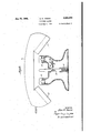
- Figure 2 is a sectional view of a typical form' of telephone including a pulsating contact or pule sating switch for actuating the signalling tubes at the switchboard.
- One of the lines consisting of the conductors l and II is connected to a jack
- the tube will continue to glow until the The transmitter 50 and receiver are illustrated diagrammatically as in a French type of handset ( Figure '2) with the switch 52 interposed between the line I and the receiver 5
- is connected by means of a conductor 53, and the secondary winding 54 of a transformer 55 to the line Ill.
- the transmitter 50 is connected by means of the conductor 53, a hookswitch 56 to one pole of a battery 51, through the other pole of the battery 51 to the primarywinding 63 of the transformer 55 and to the other side oi the transmitter 50 thereby constituting a talking circuit when hookswitch 56 nected to the cathode l8 of a gas type electronic tube I9.
- the jack contact I3 is normally in engagement with a contact l5 which is connected by a conductor Hi to one'poleof a battery 11 or other source of direct current.
- 9 is valso provided with a grid 2
- the grid 20 of the tube is connected by means of a conductor 22 through a resistor 23 to the contact M of the jack.
- of the tube I9 is connected throughlaresistor 24 and a conductor 25 to the other pole' of the battery IT.
- the coil 26 of a relay 21 may be interposed for controlling the operation of an audible signal such as an alarm bell or buzzer (not shown) if desired.
- the jack I2 is provided with a third contact 28 for a purpose to be described later. This third contact 28 is connected to the conductor 25.
- of the'second tele- 1 phone line are similarly connected to the contacts 32 and 33 of a jack 34.
- the contact 32 of this J'ack' isconnected'to the cathode 31 of the tube
- Thecircuit is completed by connecting the plate 40 of the tube 39 through the resistor 29 to the conductor 25. i'The contact 4
- the contact 62 of the switch GI is resiliently supported and normally is Spaced from the contact 60.
- the end of the contact 52 may be disposed adjacent to a rod 66 that is depressed by the .weight of the handset H but is urged upwardly at all'time's by means of a spring 611
- the rod 66 supports pivotally a pawl '68 that is arrangedito. tilt and pass by the contact 62 when rod 56 moves upwardly.
- the pawl 68 is so arranged that on downward movement of the rod 65 either. by manually operating the rod with the finger or hanging up.
- the pawl 88 will engage contact 62 displace it downwardly and then release it so that the contact 62 can vibrate into and out of engagement with the'contact 68.
- the handset'I-l is lifted and the rod' 66 is depressed manually to set the contact 62 into vibration.
- the switches 52 and 56 are normally held open when the handset is on its cradle, but are closed when the handset is lifted to connect the transmitten 50'and receiver 5
- the cord circuit .for connecting the operator to the lines and for connecting the lines to each other is shown diagrammatically in Fig. 1-.
- the cord circuit for connecting the operator to the lines and for connecting the lines to each other is shown diagrammatically in Fig. 1-.
- A. telephone system comprising a; plurality of telephone sets, each having a transmitteriand a receiver, a switchboard having a plurality of gas-type, electronic tubes forming "signalling means corresponding to each telephone set, each tube having a plate, a grid and a. cathode and being adapted to glow uponapplication of potentials of proper magnitude to the grid, plate and cathode, a separate jack at the switchboard for each of said telephone sets and connecting said telephone sets to said cathode and said grid of the corresponding tube, means for applying a potential to said cathode.
- a telephone system comprising,a plurality of telephone sets, each having a transmitter and a receiver, a switchboard having a plurality of gas-type electronic tubes forming signalling means correspondingto each telephoneset, each tube having a plate, a grid and a cathode and being adapted to glow upon application of potentials of proper magnitude to the grid, plateand cathode, a separate jack at the switchboard connected to each of said telephone sets, means electrically connecting said telephone sets to said cathode and to saidgrid of the corresponding tube, means including a pair of disengageable contacts in each of said jacks, for applying a potential to said cathode andtosaid plate, means for supplying a potential to the plate, and cathode of said corresponding tube of insufficient magnitude to cause said tube to glow, means.
- a switchboard having a plurality of three-element, gas-type electronic tubes, each corresponding to a telephone set and being adapted to ignite and glow upon application of potentialsof proper magnitude to the elements thereof, means for applying to the eleeinnts of said tubes potentials of insufiicient magnitude to ignite the tubes but sufliciently high to cause the tubes to continue glow after ignition, means operable'at each telephone set for supplying a potential sumcient to ignite its corresponding tube, and means operable at the switchboard for disconnecting at least one elementof the tube from the potential supplying, means to extinguish a glowingtube.
- a switchboard having a plurality of three-element, gas type electronic tubes, each corresponding to 'a telephone set and being adapted to ignite and glow upon application of potentials'of proper magnitude to the elements thereof, means forja'pplying to the elements of said tubes potentials of ins'ufiicient magnitude toignite the tubes butfsuflicie'ntly high to cause the tubes to continue glow after ignition, means operable at each telephone set for supplying a potential sufficient to ignite its corresponding tube, an operators telephone set 'at said switchboard, contact means ,for' connecting said operator's set selectively to any of, the other telephone.
- a telephone system comprising a plurality of telephone sets,;a switchboard for selectively .connecting said telephone setsto each, other, multiple element, gas-type electronic tubes at said switchboard corresponding to each telephone set, each tube being adapted to glow uponapplication of proper potentials to the elements.
- a telephone system comprising a plurality of telephone sets, a switchboard for-selectively .con-
- each tube being adapted to" glow upon application of proper potentials to the elements thereof, means for applyingto said elements potentials of insufllcient' magnitudeto cause said; tubes' to glow,
- a switchboard having a plurality of three-element, gas-type electronic tubes, each corresponding to a telephone set and being adapted to ignite ,and glow upon application of pot ntials of proper magnitude to the elements thereof, means'for applying to the elements of said tubes potentialsof insufiicient magnitude .to ignite the tubes but sufliciently high to cause the tubes tojcontinueglow after ignition, meansoperable' at each'telephone set for supplying a potential suflicient to ignit e its corresponding tube, an operators telephone set at said switchboard, contact means for connecting said operators setselec'tively to any "of the other telephone sets and simultaneouslydiscon necting atleast one element of the'corr'esponding tube from the potential supplying 'means,”and means including said contact means operable at said switchboard for connecting said other telephone sets selectively to each other,'a three-element, gas-type electronic tube electrically connected to said contact means
Landscapes
- Engineering & Computer Science (AREA)
- Signal Processing (AREA)
- Telephonic Communication Services (AREA)
Description
Jan. 22, 1946. D. H. YOUNG I 2,393,354
TELEPHONE" SYSTEM Filed May 5, 1944 2 Sheets-Sheet 1 IMP IN VEN TOR.
2 Jay/1x )wva Jan. 22, 1946. D. H. YOUNG- I 2,393,354
TELEPHONE SYSTEM I I Filed ma 5, 1944 y 2 Sheets-Shea 2 BY Jam/9f You/vs Az'ramyr INVENTOR.
ode l8 and the plate 2|.
39 which is similar to the tube l9. 32 of the jack is engageable with contact 35 which retaining all of the advantages of the local battery type of system.
For a better understanding of the present in V vention, reference may be had to the n accompanying drawings, in which:
Figure 1 is a simplified diagrammatic showing of a circuit for two telephones, embodying the 1 present invention;
Figure 2 is a sectional view of a typical form' of telephone including a pulsating contact or pule sating switch for actuating the signalling tubes at the switchboard.
I The embodiment of the invention chosen for illustration is disclosed in the drawings, as applied to a telephone system including a switchboard circuithaving two, two-wire telephone lines con nected therewith. It will be understood that the switchboard may be provided with connections for as many lines as may be required.
One of the lines consisting of the conductors l and II is connected to a jack |2 having two contacts l3 and I4 connected respectively to lines In and Contact [2 of the jack is also con- From the preceding description of the switchboard line circuit it will be apparent that the potential of the battery I! will be impressed upon the cathodes I8 and 31 and the plates 2| and 40 of the tubes l9 and 39. It will also be apparent that the cathodes l8 and 31 and the grids 2|] and 38 will be connected to the telephone lines. Whenva potential is impressed on the telephone lines and consequently on the cathode and grid of a tube l9 or 39, it will cause the gases in the tube to ionize, thereby causing the tube to glow. The tube will continue to glow until the The transmitter 50 and receiver are illustrated diagrammatically as in a French type of handset (Figure '2) with the switch 52 interposed between the line I and the receiver 5|. The opposite side of the receiver 5| is connected by means of a conductor 53, and the secondary winding 54 of a transformer 55 to the line Ill. The transmitter 50 is connected by means of the conductor 53, a hookswitch 56 to one pole of a battery 51, through the other pole of the battery 51 to the primarywinding 63 of the transformer 55 and to the other side oi the transmitter 50 thereby constituting a talking circuit when hookswitch 56 nected to the cathode l8 of a gas type electronic tube I9. The jack contact I3 is normally in engagement with a contact l5 which is connected by a conductor Hi to one'poleof a battery 11 or other source of direct current. The gas type electronic tube |9 is valso provided with a grid 2|) the plate 2|, but which is normally inactive even though potentials are applied between the oath- When an additional potentialis'applied between the cathode l8 and the grid the tube becomes active and current it will continue to glow until the battery circuit ofthe tube is opened or the voltage is reduced.
The grid 20 of the tube is connected by means of a conductor 22 through a resistor 23 to the contact M of the jack. The plate 2| of the tube I9 is connected throughlaresistor 24 and a conductor 25 to the other pole' of the battery IT. The coil 26 of a relay 21 may be interposed for controlling the operation of an audible signal such as an alarm bell or buzzer (not shown) if desired. The jack I2 is provided with a third contact 28 for a purpose to be described later. This third contact 28 is connected to the conductor 25.
The conductors 30 and 3| of the'second tele- 1 phone line are similarly connected to the contacts 32 and 33 of a jack 34. The contact 32 of this J'ack'isconnected'to the cathode 31 of the tube The contact grid 38 of the tube 39. Thecircuit is completed by connecting the plate 40 of the tube 39 through the resistor 29 to the conductor 25. i'The contact 4| of the jack 34 is connected to the conductor 25.
flows between the cathode '|8 and the plate'2l causing it to glow. When the tube I9 is started,
nected by means of a conductor to'the primary winding 58 of a step-up transformer 59.' The opposite end of the winding 58 is connected to one contact 60 of a pulsating switch 8| (Figure 2) which is normally spacedfrom the other contact ,62 of the switch 6l. The contact 82 is connected to the opposite pole of the battery 51. An audible signal member 64 is also connected to telephone line In and to indicate incoming calls in the conventional manner. I
' 'As illustrated in Figure 2, the contact 62 of the switch GI is resiliently supported and normally is Spaced from the contact 60. The end of the contact 52 may be disposed adjacent to a rod 66 that is depressed by the .weight of the handset H but is urged upwardly at all'time's by means of a spring 611 The rod 66 supports pivotally a pawl '68 that is arrangedito. tilt and pass by the contact 62 when rod 56 moves upwardly. The pawl 68 is so arranged that on downward movement of the rod 65 either. by manually operating the rod with the finger or hanging up. the handset H, the pawl 88 will engage contact 62 displace it downwardly and then release it so that the contact 62 can vibrate into and out of engagement with the'contact 68. When a call is to be made, the handset'I-l is lifted and the rod' 66 is depressed manually to set the contact 62 into vibration.
Inasmuch as the switch 6| is in the circuit containing the battery 51 and the primary 58 oi the transformer 59, 'a pulsating current is generated by vibration of the contact 62 which is stepped up in the secondary winding 65 to increase the potential applied to the grid 20 of the tube l9 'sufliciently'to ionize the gas therein and cause the tube l9 to glow onthe switchboard. The relay 21 will be actuated by the flow of current to thetube Hi to actuate the audible or other signalling means.
The switches 52 and 56 are normally held open when the handset is on its cradle, but are closed when the handset is lifted to connect the transmitten 50'and receiver 5| to the lines l0 and H.
The cord circuit .for connecting the operator to the lines and for connecting the lines to each other is shown diagrammatically in Fig. 1-. The
glow.
grid .of-- its corresponding tube, and vibratable switch means operable at said telephone setior supplying a sufliciently high potential to said grid to ionize the gas inthe-corresponding tube and 7 cause said tubeto glow.
3. A. telephone system, comprising a; plurality of telephone sets, each having a transmitteriand a receiver, a switchboard having a plurality of gas-type, electronic tubes forming "signalling means corresponding to each telephone set, each tube having a plate, a grid and a. cathode and being adapted to glow uponapplication of potentials of proper magnitude to the grid, plate and cathode, a separate jack at the switchboard for each of said telephone sets and connecting said telephone sets to said cathode and said grid of the corresponding tube, means for applying a potential to said cathode. and said plate, means for supplying a potential to the ,plateand cathode of said corresponding tube of insuificient magnitude to cause said tube to glow, and means operable at each telephone set for supplyinga potential to the grid of the corresponding tubeof suflicient magnitude to cause the corresponding tube to glow. c
4. A telephone system comprising,a plurality of telephone sets, each having a transmitter and a receiver, a switchboard having a plurality of gas-type electronic tubes forming signalling means correspondingto each telephoneset, each tube having a plate, a grid and a cathode and being adapted to glow upon application of potentials of proper magnitude to the grid, plateand cathode, a separate jack at the switchboard connected to each of said telephone sets, means electrically connecting said telephone sets to said cathode and to saidgrid of the corresponding tube, means including a pair of disengageable contacts in each of said jacks, for applying a potential to said cathode andtosaid plate, means for supplying a potential to the plate, and cathode of said corresponding tube of insufficient magnitude to cause said tube to glow, means. operable at each telephone set for supplying a potential to the grid of the corresponding tube of ing a potential of sumciently great magnitude to the corresponding tube to cause said tube to glow, an operators' telephone set at said switchboard, means for connecting said operator's set selective 1y to any of the other telephone sets, and means operable upon connection of said operators telephone set to another telephone set for disconnecting the corresponding tube from at least one of said means for supplying potentials.
7. In a telephone system having a plurality of telephone sets, the combination of ,a switchboard having a plurality of three-element, gas-type electronic tubes, each corresponding to a telephone set and being adapted to ignite and glow upon application of potentialsof proper magnitude to the elements thereof, means for applying to the eleeinnts of said tubes potentials of insufiicient magnitude to ignite the tubes but sufliciently high to cause the tubes to continue glow after ignition, means operable'at each telephone set for supplying a potential sumcient to ignite its corresponding tube, and means operable at the switchboard for disconnecting at least one elementof the tube from the potential supplying, means to extinguish a glowingtube.- ,ff
8. In a telephone'system having alplurality'of telephone sets, the combination of a switchboard having a plurality of three-element, gas type electronic tubes, each corresponding to 'a telephone set and being adapted to ignite and glow upon application of potentials'of proper magnitude to the elements thereof, means forja'pplying to the elements of said tubes potentials of ins'ufiicient magnitude toignite the tubes butfsuflicie'ntly high to cause the tubes to continue glow after ignition, means operable at each telephone set for supplying a potential sufficient to ignite its corresponding tube, an operators telephone set 'at said switchboard, contact means ,for' connecting said operator's set selectively to any of, the other telephone. sets and simultaneously disconnecting at least one element of the corresponding tube from the potential supplying means, and means including said contact means operable at said sufiicient magnitude to cause the corresponding tube to glow, an operators telephone set at, said switchboard having a plug'to bereceived in any of said jacks, and means on said plugs for disengaging said, disengageable contacts of the jack receiving the plug and extin uishing said tube.
5. A telephone system comprising a plurality of telephone sets,;a switchboard for selectively .connecting said telephone setsto each, other, multiple element, gas-type electronic tubes at said switchboard corresponding to each telephone set, each tube being adapted to glow uponapplication of proper potentials to the elements. thereof,
means for applying to said elements potentials of insufiicient magnitude to cause said tubes to glow but of sufficient magnitude to cause the tube tocontinue to glow after it has been started and means operable at said telephone sets for supplying a potentialof sufficiently great magnitude to the corresponding tubeto cause said tube, to
6. A telephone system comprising a plurality of telephone sets, a switchboard for-selectively .con-
necting saidtelephone sets to each othenthreeelement, gas-type electronic tubes at said switchboard corresponding to ea'chftelephone set, each tube being adapted to" glow upon application of proper potentials to the elements thereof, means for applyingto said elements potentials of insufllcient' magnitudeto cause said; tubes' to glow,
'means operable at said telephone-sets forsupplyswitchboard for connecting said other telephone sets selectively to each other. i r
9. In a telephone system havinga plurality of telephone sets, the combination of a switchboard having a plurality of three-element, gas-type electronic tubes, each corresponding to a telephone set and being adapted to ignite ,and glow upon application of pot ntials of proper magnitude to the elements thereof, means'for applying to the elements of said tubes potentialsof insufiicient magnitude .to ignite the tubes but sufliciently high to cause the tubes tojcontinueglow after ignition, meansoperable' at each'telephone set for supplying a potential suflicient to ignit e its corresponding tube, an operators telephone set at said switchboard, contact means for connecting said operators setselec'tively to any "of the other telephone sets and simultaneouslydiscon necting atleast one element of the'corr'esponding tube from the potential supplying 'means,"and means including said contact means operable at said switchboard for connecting said other telephone sets selectively to each other,'a three-element, gas-type electronic tube electrically connected to said contact means, means engageable with said contactmeans for connecting the lastmentioned tube to said means for supplying potentials and to said means operable at said tele phone sets, whereby actuation of the last-mentioned means ignites and causes the last -mentioned tube to glow. L i I v I DON -H.-YOUNG.
Disclaimer 2,393,3 54.Don H. Young, Valley Stream, N. Y. TELEPHONE SYSTEM. Patent dated Jan. 22, 1946. Disclaimer filed May 5, 1948, by the assignee, Dictagmph Products Company, Inc.
Hereby disclaims claim 1 and claims 3 to 8 inclusive, of said patent.
[Ofiicial Gazette June 8, 1948.]
Priority Applications (1)
| Application Number | Priority Date | Filing Date | Title |
|---|---|---|---|
| US534202A US2393354A (en) | 1944-05-05 | 1944-05-05 | Telephone system |
Applications Claiming Priority (1)
| Application Number | Priority Date | Filing Date | Title |
|---|---|---|---|
| US534202A US2393354A (en) | 1944-05-05 | 1944-05-05 | Telephone system |
Publications (1)
| Publication Number | Publication Date |
|---|---|
| US2393354A true US2393354A (en) | 1946-01-22 |
Family
ID=24129101
Family Applications (1)
| Application Number | Title | Priority Date | Filing Date |
|---|---|---|---|
| US534202A Expired - Lifetime US2393354A (en) | 1944-05-05 | 1944-05-05 | Telephone system |
Country Status (1)
| Country | Link |
|---|---|
| US (1) | US2393354A (en) |
Cited By (1)
| Publication number | Priority date | Publication date | Assignee | Title |
|---|---|---|---|---|
| US2435302A (en) * | 1946-04-03 | 1948-02-03 | Dictograph Products Co Inc | Telephone system having a calling and supervisory signaling device |
-
1944
- 1944-05-05 US US534202A patent/US2393354A/en not_active Expired - Lifetime
Cited By (1)
| Publication number | Priority date | Publication date | Assignee | Title |
|---|---|---|---|---|
| US2435302A (en) * | 1946-04-03 | 1948-02-03 | Dictograph Products Co Inc | Telephone system having a calling and supervisory signaling device |
Similar Documents
| Publication | Publication Date | Title |
|---|---|---|
| US2373134A (en) | Signaling system | |
| US4121053A (en) | Telephone command apparatus | |
| US2951911A (en) | Arrangement for automatic signalling system intended for transmitting voice-frequency calling signals | |
| US2393354A (en) | Telephone system | |
| US1917995A (en) | Radio telephony | |
| US3064236A (en) | Selective signaling system | |
| GB714667A (en) | Improvements in or relating to electronic data-storing circuits | |
| GB573869A (en) | Improvements in or relating to electric impulse receiving arrangements | |
| GB877005A (en) | Terminal control circuit | |
| US3374317A (en) | Telephone signaling system | |
| US2461241A (en) | Telephone alarm system | |
| US2278410A (en) | Telephone system | |
| US3288932A (en) | Voice-data substation apparatus actuated by tone from central switching office | |
| US2294464A (en) | Impulse transmitter | |
| USRE23057E (en) | atkins | |
| US3008009A (en) | Arrangement for automatic signalling system intended for receiving voicefrequency calling signals | |
| US2288251A (en) | Automatic toll switching telephone system | |
| US2435302A (en) | Telephone system having a calling and supervisory signaling device | |
| US3597551A (en) | In-band signalling apparatus | |
| US2410050A (en) | Telecommunication switching system | |
| US3003038A (en) | Multiple station intercommunication system | |
| US2193505A (en) | Apartment house signaling and telephone system | |
| US1967404A (en) | Signaling apparatus | |
| US2345953A (en) | Telegraph repeater | |
| US3259698A (en) | Solid state intercommunication system |